1
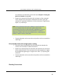
NLC‐100D Installation and troubleshooting NETAFIM LANDSCAPE CONTROLLERS
NLC-100D
INSTALLATION & TROUBLESHOOTING MANUAL
NLC-100D
1
NLC‐100D Installation and troubleshooting
Copyright January 2014. All rights reserved. No part of this publication may be reproduced, stored in a retrieval system, or transmitted in any form or by any means electronic, mechanical, photocopying, recording or otherwise without the prior permission of the publisher.
Netafim USA
5470 E. Home Ave.
Fresno, CA 93727
Phone:
(888) 638‐2346
(559) 453‐6800
Fax: (559) 453‐6803
Email:
[email protected]
450-230-0005/A
2
NLC‐100D Installation and troubleshooting Table of Contents
Chapter 1: Introduction ........................................................................................................... 7
The Two‐wire Technology ................................................................................ 7
Two‐wire layout: ..................................................................................7
Conventional layout: ...........................................................................8
The Controller .......................................................................................... 8
The decoders ............................................................................................ 9
Irrigation Features .................................................................................... 9
Chapter 2: System Installation ............................................................................................... 11
Mounting the Controller ............................................................................... 11
Marking up the mounting holes ............................................................. 12
Connecting the Controller ............................................................................. 14
Grounding the Controller ....................................................................... 15
Connecting 2‐wire ......................................................................................... 16
Connecting Sensors ....................................................................................... 17
Connecting an ET Device ............................................................................... 17
Using a Connected Device (weather station) ................................................. 18
Configuring ET Input ............................................................................... 18
Checking the Current Aggregated ET and Rain .............................................. 26
Reading current aggregated ET and Rain figures ..................................... 26
Connecting a Rain Sensor .............................................................................. 29
Configuring for a Rain Sensor ................................................................. 30
Setting Hourly Maximum Rain and Rain Alarm Level ..................................... 35
Setting the Hourly Max. Rain and Rain Alarm Level ................................ 36
Connecting a Flow Sensor ............................................................................. 39
Enabling Flow Sensor Input (pulses) .............................................................. 40
Enabling flow sensor pulse input in the NLC ........................................... 40
Configuring for Flow Sensor Input ................................................................. 41
3
NLC‐100D Installation and troubleshooting
Selecting Sensor Type ............................................................................. 42
Using a built‐in calibration profile .......................................................... 42
Setting the Flow Sensor Adjustment ....................................................... 46
Adjusting the flow sensor input .............................................................. 46
Viewing the Current Flow ............................................................................. 47
Connecting an Alarm ..................................................................................... 49
Connecting a Moisture sensor ...................................................................... 50
Connecting, Configuring and Using Moisture Sensors ................................... 50
Connecting and configuring a moisture sensor ....................................... 51
Assigning an ID to a soil moisture sensor ............................................... 51
Configuring a soil moisture sensor ......................................................... 55
Chapter 3: Entering Moisture Sensor License........................................................................ 59
Chapter 4: Troubleshooting from the Controller................................................................... 63
Testing decoders ........................................................................................... 63
Running the "Electrical Test" .................................................................. 63
Running the decoder test ..................................................................63
Special current readings from the decoder test ................................65
Testing Individual Decoders .................................................................... 66
Running the "Water Test" .............................................................................. 66
Running the test program ....................................................................... 66
Testing Programs ........................................................................................... 68
Testing the Two‐wire Path ............................................................................. 69
Making the controller display voltage/current .................................70
The Built‐in Short Test ............................................................................ 71
Running the short test .......................................................................71
Increasing decoder Power ............................................................................. 74
Chapter 5: Troubleshooting in the field ................................................................................. 77
Checking Power and Current Readings .......................................................... 77
Scenarios with power readings between 31V and 35V .....................80
4
NLC‐100D Installation and troubleshooting Problems on the Two‐wire ..................................................................... 81
Dealing with Unstable decoders .................................................................... 81
Dealing with Failing decoders ................................................................. 83
A Single decoder Fails ........................................................................83
If there's little or no reaction from the decoder: ..............................83
If the decoder fails with to high power reading ................................84
Checking Connections .......................................................................84
Testing the path to a decoder ...........................................................85
Several decoders Fail .............................................................................. 85
Checking a branch .............................................................................87
When there is a Short Circuit in the Field ...................................................... 88
Using a Current Tracker .......................................................................... 91
Locating a short on the two‐wire ......................................................92
Rotating the current tracker around the two‐wire ...........................93
Using a Clampmeter ............................................................................... 94
Using a clampmeter for short finding ................................................94
Locating the Short .............................................................................94
Phase I: Checking for Problems at the Controller ..............................95
Phase II: Locating a Faulty Branch in the Field ..................................96
Phase III: Performing a "Binary Search" on a Faulty Branch ..............98
5
NLC‐100D Installation and troubleshooting
6
NLC‐100D Installation and troubleshooting Chapter 1: Introduction
The NLC is a microprocessor based irrigation control system. A central controller and up to 100 field decoders comprise a complete system. In addition the controller will accept input from several external sensors in order to adjust its irrigation to the local weather conditions.
Communication between the controller and the decoders happens over a two‐wire path. Depending on the signal from the controller, the decoders each activate or deactivate a valve. The controller signals to the decoders based on configurable schedules, eliminating the need for human interaction when the park, garden or other surroundings need watering ‐ once set up, the NLC runs on its own.
The Two‐wire Technology
The NLC uses two‐wire transmission technology to tell the decoders when to act. This means that instead of laying out a cable to each individual valve, just one or two single cables are laid out, and the decoders all connect to the same cable(s):
Two‐wire layout:
In contrast, this is how the above system would look using a conventional irrigation system that needs a dedicated cable to each individual valve:
7
NLC‐100D Installation and troubleshooting
Conventional layout:
The two‐wire technology has several obvious advantages over a conventional system:
• Ease of installation:You are only handling one roll of wire.
•
Ease of expansion: When you need to add a decoder in the field, you don't have to dig in a new cable and risk damaging the existing web of cables already in the ground ‐ you simply attach the new decoder to the existing cable.
• Cost reduction: You save money on expensive copper cable ‐ using 20% compared to traditional cabling.
The Controller
The heart of a two‐wire system is the controller. This is a microprocessor controlled device that stores your irrigation programs and sends signals on the two‐wire path, telling the individual decoders in the field when to activate their valve.
In the case of NLC, the controller doubles as a decoder programmer, allowing you to manage the identities of all decoders in your system.
8
NLC‐100D Installation and troubleshooting The decoders
decoders in an NLC system are mainly concerned with two specific commands: "start" and "stop". Depending on whether they are attached to an irrigation valve, a booster pump relay or a master valve, the decoders will start and stop the device according to the instructions they get over the two‐wire path.
Irrigation Features
Here are the main features that the NLC utilizes to help you automate your irrigation:
• Controls up to 100 field decoders, attached to valves or relays.
• Provides ET corrected irrigation for optimal adjusted water consumption.
• Measures water flow and raises alarms or halts irrigation on unexpected flow.
• Operates over as much as 6000 feet of AWG16 cable.
• Allows for 10 independent irrigation programs. In addition there is a fixed test program that activates all 100 decoders in turn.
• A program can activate up to 100 decoders in named order.
• Each decoder can run for up to 17:59:50 (In fact, you can boost this even further by increasing the "water budget". • Each program can activate a one or more booster pumps in addition to the decoders.
• All programs have 12 start times per day.
• All programs can run simultaneously.
• You configure each program to run on any selection of days in a 14 day period, or on odd/even dates.
• You can activate one or more valves or programs manually while one or more programs are running, up to a total of 12 simultaneously running valves.
9
NLC‐100D Installation and troubleshooting
• A master valve can be selected that will open when any program or decoder is run.You typically assign master valve status to the valve controlling access to municipal water or pumping decoder.
• Up to 10 moisture sensors that can monitor soil moisture and adjust irrigation accordingly.
10
NLC‐100D Installation and troubleshooting Chapter 2: System Installation
Mounting the Controller
Though the NLC is designed to resist both rain and direct sun light, you should place it in a friendlier environment if possible. Installing the NLC inside a utility room or a shed is the perfect solution, but if this is not possible, try to place it somewhere dry and out of sight.
Furthermore, make sure that you place the controller in a location that meets these requirements:
• The controller must have access to 120 VAC.
• You must be able to connect all cables to the controller at the location.
• To minimize electromagnetic interference, make sure that the controller is placed at least 15 feet away from any high‐draw motors like air conditioners, refrigerators, pool pumps etc.
Once you've designated a suitable location for the controller, you're ready to mount it on the wall ‐ or whatever vertical surface you have chosen. Here's what you are going to need in order to mount the controller properly:
• A screw driver that matches the above screws.
• A pen or a marker to mark up where to put the screws.
• If you're mounting the controller on a concrete wall you will need an electric drill.
Before you start mounting the controller you should remove the lower front plate inside the controller cabinet.
11
NLC‐100D Installation and troubleshooting
Marking up the mounting holes
1 Make sure the bracket is in level. Mark up the mounting holes.
12
NLC‐100D Installation and troubleshooting 2
Use a pen to put marks on the wall through the hole in the back of the controller cabinet.
3
If you're placing the controller on a concrete wall, take down the controller, drill out the hole, put in the wall anchor, and put back the controller on the wall.
4
Fasten the screw in the wall through the holes in the back of the controller cabinet.
13
NLC‐100D Installation and troubleshooting
Now the controller should be mounted firmly on the wall. After mounting the controller, it's time to connect the power and connect boards ‐ follow the instructions in the next section to do this.
Connecting the Controller
You need to connect two lines to the controller: the power line and the two‐wire path.
Warning
The NLC runs on 120V AC and must be installed in compliance with local electrical codes.
Unauthorized installation will void the warranty of the NLC.
You connect the two‐wire by running it through a hole in the bottom of the controller cabinet and fastening it to the two‐wire terminals (1A-1B) using a flat head screw driver:
14
NLC‐100D Installation and troubleshooting Grounding the Controller
To secure your NLC against lightning, you must ensure that the controller is grounded through a ground rod connected to the ground lug.
+-
+-
+-
+-
VDC
ET
Rain
AUX
2-Wire 2-Wire
1A-1B 2A-2B
DECODER PROGRAMMING
Warning
You will void the warranty by not grounding your NLC properly.
15
NLC‐100D Installation and troubleshooting
Connecting 2‐wire
There's room for connecting two cables directly to the controller ‐ the other line can be connected to the terminals labeled 2A-2B. Both wires will receive the same signals when the controller is up and running.
16
NLC‐100D Installation and troubleshooting Connecting Sensors
The NLC takes input from different sensor types: ET devices, rain sensors, flow sensors and regular auxiliary alarms. This sections shows you how to connect these sensors to the controller.
Connecting an ET Device
The NLC supports ET in two ways:
1 "ET Enabled" mode in which the controller just lets an external device tell it when to irrigate and when to stay passive. In this mode the controller supports a WS ET device. To make the controller receive instructions from an ET device, connect the "ET enable A" from the device to the green terminals labeled "ET."
2
"ET Pulses" mode where you connect a weather station that continuously tells the controller how much water is evaporating. Combined with the input from a rain sensor the controller will then on its own figure out how much to irrigate. Running in this mode you still just connect the weather station to the ET terminals.
+-
+-
+-
+-
VDC
ET
Rain
AUX
2-Wire 2-Wire
1A-1B 2A-2B
DECODER PROGRAMMING
17
NLC‐100D Installation and troubleshooting
Important! Be aware of the polarity when you connect devices to the NLC: Connect plus to plus and minus to minus or you won't see the expected behavior from the connected devices.
Using a Connected Device (weather station)
Connecting an ET device on‐site gives you the most accurate adjustments as the ET device will monitor the exact weather condition right where irrigation will take place.
Important! If for some reason your weather station fails and does not provide any input for the NLC the controller will fall back on historical ET data and use these instead. The same goes in case of a power failure ‐ the controller will use the historical data for the part of today that lies before the power failure, and then use real‐time ET data from when it is powered up again. Bottom line: you should always enter a set of historical ET data even when running with a connected weather station.
Configuring ET Input
1 Before moving on, make sure you have connected the ET device. 2
Turn the dial to ADVANCED
18
NLC‐100D Installation and troubleshooting PAUSE/
RESUME
STOP
MANUAL
OFF
RAIN OFF
RAIN ALARM STATUS
VIEW ALARMS
VIEW ET & RAIN
VIEW MOISTURE SENSOR
SETUP SENSORS
AUTO
SET DATE & TIME
PROGRAM
RUN TIME
WATER DAYS
START TIME
WATER BUDGET / ET
PROGRAM STATUS
ADVANCED
SOLENOID AMPS
Now the display looks like this:
3
Use the item selectors to select 3. Intelliset and push the ENTER
button. Now you'll see the following screen:
19
NLC‐100D Installation and troubleshooting
4
Select 6. Device Setup. Now the display will look like this:
5
Select 1. ET Input Method. Now the display will look like this:
6
Use the item selectors to select Local Weather station and push the ENTER button.
20
NLC‐100D Installation and troubleshooting 7
Select 3. ET Base Setup from the menu and push the ENTER
button. Now you'll see the following screen:
Note: See the NLC 100 User Manual for more information about Base ET.
8
For each program, use the item selectors to determine how many inches of water the program will provide when running at a 100% water budget. The controller needs this in order to re‐calculate run times based on ET corrections.
Push the ENTER button to save the value.
9
Push the CANCEL button once to return to the main Intelliset™
menu.
10 Use the item selectors to select 2. ET Limits (Min and Max) and push the ENTER button. Now you'll see the following screen:
21
NLC‐100D Installation and troubleshooting
11 Now use the item selectors to determine the two values and push ENTER to save your settings: • Minimum ET: The ET figure must exceed this value in order for the controller to irrigate at all.
• Maximum ET: If the ET balance for a program exceeds this value, the program will only irrigate to that limit, and the remaining water will be added to the ET figure for the following day.
12 Turn the dial to SETUP SENSORS:
PAUSE/
RESUME
STOP
MANUAL
OFF
RAIN OFF
RAIN ALARM STATUS
VIEW ALARMS
VIEW ET & RAIN
VIEW MOISTURE SENSOR
SETUP SENSORS
AUTO
SET DATE & TIME
PROGRAM
RUN TIME
WATER DAYS
START TIME
WATER BUDGET / ET
PROGRAM STATUS
ADVANCED
SOLENOID AMPS
Now the display looks like this:
22
NLC‐100D Installation and troubleshooting 13 Use the item selectors to select 1. ET and push the ENTER button.
Now the display looks like this:
14 Now you can choose between four settings:
ET device (Pulses)
Select this if you use a connected ET device that provides dynamic ET data for the controller (ET-300-W weather station.)
ET enabled (N/O or N/C)
If your ET device simply tells the controller whether to irrigate or not, you need to tell the controller if the input is normally open (N/O) or normally closed (N/C). Whenever the device is then in the opposite mode, the controller will hold its irrigation. This is typically a WR7 Receiver.
23
NLC‐100D Installation and troubleshooting
Disabled
Don't use the ET input.
Use the item selectors to locate the setting you want and if you chose anything but ET device (Pulses), push the ENTER button to save your selection and the SENSORS button to exit sensor configuration.
If you chose ET device (Pulses), you need to tell the controller how many inches to the current ET figure per pulse it receives ‐ please proceed to the next step (default setting is 0.01".)
15 Turn the dial to ADVANCED
PAUSE/
RESUME
STOP
MANUAL
OFF
RAIN OFF
RAIN ALARM STATUS
VIEW ALARMS
VIEW ET & RAIN
VIEW MOISTURE SENSOR
SETUP SENSORS
AUTO
SET DATE & TIME
PROGRAM
RUN TIME
WATER DAYS
START TIME
WATER BUDGET / ET
PROGRAM STATUS
ADVANCED
SOLENOID AMPS
Now the display looks like this:
24
NLC‐100D Installation and troubleshooting 16 Use the item selectors to select 3. Intelliset and push the ENTER
button. Now you'll see the following screen:
17 Select 6. Device Setup. Now the display will look like this:
25
NLC‐100D Installation and troubleshooting
18 Select 2. ET and Rain Inch/Pulse Settings. Now you'll see something like this:
19 Use the item selectors to set your values and push the ENTER button to save your settings.
Checking the Current Aggregated ET and Rain
Every now and then you might want to check out how much rain has fallen or how much water has evaporated ‐ the NLC has a screen that shows you the accumulated values in real time:
Reading current aggregated ET and Rain figures
1 Turn the dial to ADVANCED
26
NLC‐100D Installation and troubleshooting PAUSE/
RESUME
STOP
MANUAL
OFF
RAIN OFF
RAIN ALARM STATUS
VIEW ALARMS
VIEW ET & RAIN
VIEW MOISTURE SENSOR
SETUP SENSORS
AUTO
SET DATE & TIME
PROGRAM
RUN TIME
WATER DAYS
START TIME
WATER BUDGET / ET
PROGRAM STATUS
ADVANCED
SOLENOID AMPS
Now the display looks like this:
2
Use the item selectors to select 3. Intelliset and push the ENTER
button. Now you'll see the following screen:
27
NLC‐100D Installation and troubleshooting
3
Select 1. Current Accumulated ET and Rain from the menu and push the ENTER button. Now you'll see the following screen:
These figures will be reset at midnight when they'll be used to calculate tomorrow's ET budget.
Note: If you use a custom irrigation period, this happens at the start of your irrigation period, which might not be midnight. Please refer to the NLC User Manual.
28
NLC‐100D Installation and troubleshooting Tip:If you are running in AUTO mode and want to check the current accumulated values, you can simply push the WATER BUDGET button and you'll skip right to the above display. You exit back by pushing the WATER BUDGET button again.
This way you don't have to exit AUTO mode to check the values.
Note: To make sure that the ET device works properly, you have to wait for the device to return pulses. This will typically happen the next day.
Connecting a Rain Sensor
You can connect a rain sensor (pulse or switch) to the NLC via the grey terminals labeled "Rain":
+-
+-
+-
+-
VDC
ET
Rain
AUX
2-Wire 2-Wire
1A-1B 2A-2B
DECODER PROGRAMMING
29
NLC‐100D Installation and troubleshooting
Important! Be aware of the polarity when you connect devices to the NLC: Connect plus to plus and minus to minus or you won't see the expected behavior from the connected devices.
The NLC can accept input from an external rain sensor or a tipping rain bucket, and react in three ways:
• Simply stop irrigating if it rains at all (works with sensors and tipping rain bucket.)
• Stop irrigating if the rain level exceeds a certain threshold (works with sensors and tipping rain bucket.)
• Adjust irrigation based on the amount of rain (only works with a tipping rain bucket.)
Note: In a master/slave setup you do not need a rain sensor connected to all slaves ‐ the master can simply send out alarms to all slaves instead.
The following procedure walks you through configuring the controller for rain sensor input ‐ it is identical to parts of the procedure for ET.
Configuring for a Rain Sensor
1 Before moving on, make sure you have connected the rain sensor. For more information refer to the separate Installation and Troubleshooting manual.
2
Turn the dial to SETUP SENSORS:
30
NLC‐100D Installation and troubleshooting PAUSE/
RESUME
STOP
MANUAL
OFF
RAIN OFF
RAIN ALARM STATUS
VIEW ALARMS
VIEW ET & RAIN
VIEW MOISTURE SENSOR
SETUP SENSORS
AUTO
SET DATE & TIME
PROGRAM
RUN TIME
WATER DAYS
START TIME
WATER BUDGET / ET
PROGRAM STATUS
ADVANCED
SOLENOID AMPS
Now the display looks like this:
3
Use the item selectors to select 2. Rain and push the ENTER
button.
Now the display looks like this:
31
NLC‐100D Installation and troubleshooting
4
Now you can choose between three settings:
Rain gauge (Pulses)
If your rain sensor provides dynamic data in the sense that it sends a pulse for each unit of rain it detects, select Pulses.
Rain contact (N/O or N/C)
If your rain sensor simply tells the controller whether to irrigate or not (if it's raining or not), you need to tell the controller if the input is normally open or closed. Whenever the device is in the opposite mode, the controller will not irrigate.
Disabled
Don't use the Rain input.
Use the item selectors to locate the setting you want and if you chose anything but Rain gauge (Pulses), push the ENTER button to save your selection and the SENSORS button to exit sensor configuration.
If you do chose Rain gauge (Pulses), you need to tell the controller how many inches of rain each pulse corresponds, so please continue to the next step.
32
NLC‐100D Installation and troubleshooting Important! If you want to receive remote rain data from an ET server, you must disable your local rain sensors.
5
Turn the dial to ADVANCED
PAUSE/
RESUME
STOP
MANUAL
OFF
RAIN OFF
RAIN ALARM STATUS
VIEW ALARMS
VIEW ET & RAIN
VIEW MOISTURE SENSOR
SETUP SENSORS
AUTO
SET DATE & TIME
PROGRAM
RUN TIME
WATER DAYS
START TIME
WATER BUDGET / ET
PROGRAM STATUS
ADVANCED
SOLENOID AMPS
Now the display looks like this:
6
Use the item selectors to select 3. Intelliset and push the ENTER
button. Now you'll see the following screen:
33
NLC‐100D Installation and troubleshooting
7
Select 6. Device Setup. Now the display will look like this:
8
Select 2. ET/Rain Setup and then 2. ET and Rain Inch/Pulse
settings. Now you'll see something like this:
9
Use the item selectors to set your values and push the ENTER button to save your settings.
34
NLC‐100D Installation and troubleshooting Setting Hourly Maximum Rain and Rain Alarm Level
The NLC allows for two precautions when you experience rain:
You can set a threshold value for how much it should rain before the rain alarm will be activated. Here is how this calculation is done:
• Based on historical ET data for the area, the controller knows how much water is evaporating per day during the current season.
• The NLC assumes that 75% of the daily ET is evaporating between 8AM and 8PM, and the remaining 25% between 8PM and 8AM.
• When the amount of rain exceeds the rain alarm level you define, the rain alarm is activated.
• Now, based on the historical ET data the controller will calculate how much rain will evaporate, and mapping this number against the known amount of fallen rain, the controller will intelligently know when it is safe to turn off the rain alarm (i.e. when enough rain has evaporated that we are below your defined alarm level.)
• The soil holding value is also a parameter: since you can never benefit from more rain than the soil is capable of holding, the rain alarm will not stay on forever after a few days of intensive rain.
Note: If you have not provided any historical ET, a default of 0.20" per day is used. See more in the NCL User Manual..
• If it rains intensively for more than an hour you may get so much water that the soil can not benefit from all of it ‐ the excess water will simply run off the surface. So if you run programs in ET 35
NLC‐100D Installation and troubleshooting
corrected mode, the controller won't subtract all of the rain from tomorrow's ET figure ‐ it will "cut off" the amount of rain to subtract at the hourly maximum. Example: If the hourly maximum is 0.02" and it rains 0.03" per hour for three hours, only 0.06" and not 0.09" will be subtracted from tomorrow's ET budget.
See more in the NCL User Manual.
Setting the Hourly Max. Rain and Rain Alarm Level
1 Turn the dial to ADVANCED
PAUSE/
RESUME
STOP
MANUAL
OFF
RAIN OFF
RAIN ALARM STATUS
VIEW ALARMS
VIEW ET & RAIN
VIEW MOISTURE SENSOR
SETUP SENSORS
AUTO
SET DATE & TIME
PROGRAM
RUN TIME
WATER DAYS
START TIME
WATER BUDGET / ET
PROGRAM STATUS
ADVANCED
SOLENOID AMPS
Now the display looks like this:
36
NLC‐100D Installation and troubleshooting 2
Use the item selectors to select 3. Intelliset and push the ENTER
button. Now you'll see the following screen:
3
Select 1. ET. Now the display will look like this:
37
NLC‐100D Installation and troubleshooting
4
Select 3. Max Hourly Rain and Rain Alarm Limit from the menu and push the ENTER button. Now you'll see the following screen:
Note: Setting a value to zero is the same as disabling the feature.
Note: If you see "NA" values in this screen you have not configured a rain sensor to provide input using pulses. For more information turn to Capter 2: Configuring for a Rain Sensor on page 30.
Note: Be aware that testing the tipping rain bucket input by flipping the "spoon" will accumulate "rain" in the controller. Do it with caution as it can't be deleted by cycling the power.
Use the item selectors to set the desired values and push the ENTER button to save your settings.
38
NLC‐100D Installation and troubleshooting Connecting a Flow Sensor
A traditional flow sensor is connected to the "Aux" terminals.)
A photo diode type flow sensor is also connected to the “Aux” terminal, and via the “VDC” terminal through a resistor..
Recommended resistor values:
• 9V: 330 Ohm, 0.25 Watt
• 12V: 470 Ohm, 0.5 Watt
39
NLC‐100D Installation and troubleshooting
Enabling Flow Sensor Input (pulses)
By default flow sensor input is enabled in the NLC. To enable flow sensor input to accept pulses, follow this procedure:
Note: You can enable flow sensor input even if you haven't attached a physical sensor yet ‐ you just won't get any reading from it.
Enabling flow sensor pulse input in the NLC
1 Turn the dial to SETUP SENSORS:
PAUSE/
RESUME
STOP
MANUAL
OFF
RAIN OFF
RAIN ALARM STATUS
VIEW ALARMS
VIEW ET & RAIN
VIEW MOISTURE SENSOR
SETUP SENSORS
AUTO
SET DATE & TIME
PROGRAM
RUN TIME
WATER DAYS
START TIME
WATER BUDGET / ET
PROGRAM STATUS
ADVANCED
SOLENOID AMPS
Now the display looks like this:
40
NLC‐100D Installation and troubleshooting 2
Use the item selectors to select item number 3. Alarm/Flow and you'll see the default setting for sensor setup, Flow (Pulses):
3
Push the ENTER button to save your selection.
Now the NLC is ready to accept input from your flow sensor, but before you can use it to anything meaningful you need to configure threshold values and actions ‐ read more in the next section.
Configuring for Flow Sensor Input
In the previous section you enabled the NLC to accept flow sensor input ‐ now you need to configure what to do with it and this section walks you through the relevant procedures.
41
NLC‐100D Installation and troubleshooting
Selecting Sensor Type
By telling the NLC which type of sensor you are using, the controller can calibrate the input it receives from the input terminals. The NLC knows the calibration profiles for 12 different sensor types ‐ if you're not using one of these you'll have to skip to the next procedure to perform a manual calibration for your sensor.
Using a known sensor type to enable a built‐in profile:
Using a built‐in calibration profile
1 Turn the dial to ADVANCED, use the item selectors to scroll to item number 3. FloGuard, and push the ENTER button.
Now you'll see this display:
2
Select 4. Flow Sensor Setup, and push the ENTER button.
Now you'll see this display:
42
NLC‐100D Installation and troubleshooting 3
Choose 1. Flow Sensor Type by pushing the ENTER button.
Now you'll see this display:
4
Use the item selectors to select one of the 13 built‐in profiles:
•
1" RS
•
1" PDH
•
1.5" RS
•
1.5" PDH
•
2" RS
•
2" PDH
•
3" RS
•
3" PDH
43
NLC‐100D Installation and troubleshooting
•
4" RS
•
4" PDH
•
6" RS
•
6" PDH
•
"Custom"
5
Push the ENTER button to save your selection.
If your sensor doesn't fit any of the built-in profiles you have to enter your own manually:
Using a custom calibration profile
1 Turn the dial to ADVANCED, use the item selectors to scroll to item number 3. FloGuard, and push the ENTER button.
Now you'll see this display:
2
Select 4. Flow Sensor Setup, and push the ENTER button.
Now you'll see this display:
44
NLC‐100D Installation and troubleshooting 3
Use the item selectors to locate the Custom option and select it by pressing the ENTER button. Now you'll see the calibration screen:
Note: A bit of background on how calibration affects the calculated flow: The NLC needs to know the "K" and "Offset" values of your sensor (K‐factor and offset are the parameters of the flow meter known from the datasheet), as the actual flow will be calculated from this formula:
ActualFlow = K * (Pulses + Offset)
About the two values you need to enter:
• The "Offset" value is to correct the input from your sensor.
45
NLC‐100D Installation and troubleshooting
• The "K" value can be looked up in the data sheet for your sensor.
4
Use the item selectors to enter your values and push the ENTER
button to save your settings.
Setting the Flow Sensor Adjustment
If you want to calibrate your flow sensor, you can use the sensor adjustment to multiply the values from your sensor with anything between 0.00 and 9.99.
This comes in handy if you have a standard sensor that behaves slightly different than the built‐in profile calculates.
Adjusting the flow sensor input
1 Turn the dial to ADVANCED, use the item selectors to scroll to item number 3. FloGuard, and push the ENTER button.
Now you'll see this display:
2
Select 4. Flow Sensor Setup, and push the ENTER button.
46
NLC‐100D Installation and troubleshooting Now you'll see this display:
3
Choose 2. Flow Sensor Adjustment. Now you'll see the screen for adjusting the flow sensor input:
4
Use the item selectors to set your adjustment factor.
Push the ENTER button to save your selection.
Viewing the Current Flow
Given that you have configured your flow sensor correctly, the NLC lets you see the real time flow directly in the controller display:
47
NLC‐100D Installation and troubleshooting
1 Turn the dial to ADVANCED, use the item selectors to scroll to item number 3. FloGuard, and push the ENTER button.
Now you'll see this display:
2
Select 4. Flow Sensor Setup, and push the ENTER button.
Now you'll see this display:
3
Select 3. Current Flow Pulses and GPM and you'll see the current system flow in both pulses per second and gallons per minute:
48
NLC‐100D Installation and troubleshooting Note: The NLC can measure correctly up to a flow of 250 pulses per second. If your flow exceeds this you should use a sensor that has a higher "water amount per pulse" ratio. However, a higher frequency is to prefer over a lower one, as it provides the most accurate measuring, so in an ideal world your frequency closes in on 250 pulses per second without ever exceeding it. For more information turn to Capter 2: Selecting Sensor Type on page 42.
Connecting an Alarm
NOM
M205
BO2
M204
MV
M203
BO1
M202
ET
GND
Rain
GND
Flow
GND
V-Aux
GND
The grey terminals labeled "AUX" are intended for a regular auxiliary alarm.
COM
-
COM
-
49
NLC‐100D Installation and troubleshooting
Note: An alarm is used instead of a Flow Sensor. Turn the dial to SENSOR SETUP and select N/O eller N/C. Note: An alarm is used instead of a Flow Sensor. Turn the dial to SENSOR SETUP and select N/O eller N/C. Connecting a Moisture sensor
Connecting, Configuring and Using Moisture Sensors
This section describes how you actually get the moisture sensors ready for use and how they can improve your irrigation.
Note: The SMS are pre‐programmed, so programming is not necessary.
50
NLC‐100D Installation and troubleshooting The NLC works with the following moisture sensors:
• SMS‐100 (single sensor)
Connecting and configuring a moisture sensor
Before you can enjoy the benefits of moisture sensor input you must connect it to the moisture sensor wire, obtain a license from your distributor and perform some basic configuration.
Follow this procedure to get your moisture sensor up and running:
Note: You must have entered a license key for the controller before you are able to configure moisture sensors. Assigning an ID to a soil moisture sensor
1 Connect the soil moisture sensor to the RS232 port on the controller via an SMI‐100 interface. 2
Turn the dial to ADVANCED
51
NLC‐100D Installation and troubleshooting
PAUSE/
RESUME
STOP
MANUAL
OFF
RAIN OFF
RAIN ALARM STATUS
VIEW ALARMS
VIEW ET & RAIN
VIEW MOISTURE SENSOR
SETUP SENSORS
AUTO
SET DATE & TIME
PROGRAM
RUN TIME
WATER DAYS
START TIME
WATER BUDGET / ET
PROGRAM STATUS
ADVANCED
SOLENOID AMPS
Now the display looks like this:
3
Use the item selectors to select 3. Intelliset and push the ENTER
button. Now you'll see the following screen:
52
NLC‐100D Installation and troubleshooting 4
Select 4. Moisture Sensor Id Assign and push the ENTER button.
Now the display looks like this:
5
Select 4. Moisture Sensor Id Assign and push the ENTER button. Now
the display looks like this:
53
NLC‐100D Installation and troubleshooting
The number of sensors available in the list depends on your license.
6
Use the item selectors to choose the ID you wish to assign to the newly connected moisture sensor and push the ENTER button.
Now the controller will first check that there are no existing moisture sensors with the
ID you chose:
If no clashes in ID numbers are found, the controller moves on to detect the new
sensor:
If all goes well you will see the following message in the display:
54
NLC‐100D Installation and troubleshooting Once your moisture sensor has an ID you need to tell the controller what type of
sensor it is and in which type of soil it is placed.
Follow this procedure to make the sensor known to the NLC:
Configuring a soil moisture sensor
1 Turn the dial to ADVANCED
PAUSE/
RESUME
STOP
MANUAL
OFF
RAIN OFF
RAIN ALARM STATUS
VIEW ALARMS
VIEW ET & RAIN
VIEW MOISTURE SENSOR
SETUP SENSORS
AUTO
SET DATE & TIME
PROGRAM
RUN TIME
WATER DAYS
START TIME
WATER BUDGET / ET
PROGRAM STATUS
ADVANCED
SOLENOID AMPS
Now the display looks like this:
55
NLC‐100D Installation and troubleshooting
2
Use the item selectors to select 3. Intelliset and push the ENTER
button. Now you'll see the following screen:
3
Select 2. Moisture and push the ENTER button. Now the display looks
like this:
56
NLC‐100D Installation and troubleshooting 4
Select 2. Moisture Sensor Setup and push the ENTER button. Now
the display looks like this:
5
Use the item selectors to select the ID of the sensor you wish to configure (You assigned the ID in the previous procedure: For more information turn to Capter 2: Assigning an ID to a soil moisture sensor on page 51 and then adjust each column:
Column
Description
Whether the moisture sensor should be enabled or not.
Enable
The type of sensor associated with the ID. Supported sensors are:
• SMS‐100
Type
Soil type
The type of soil in which the sensor is placed. Options are:
• Clay
• Sand
• Loam
• Standard
6
Push the ENTER button to save your configuration.
7
Repeat steps five and six for all sensors you wish to configure.
Now the moisture sensors are ready to use, and the next sections go into detail on how you assign them to control your irrigation schedules.
57
NLC‐100D Installation and troubleshooting
58
NLC‐100D Installation and troubleshooting Chapter 3: Entering Moisture Sensor License
Note: A license is only needed if the system is expanded.
1 Turn the dial to ADVANCED
PAUSE/
RESUME
STOP
MANUAL
AUTO
SET DATE & TIME
OFF
PROGRAM
RAIN OFF
RUN TIME
RAIN ALARM STATUS
WATER DAYS
VIEW ALARMS
START TIME
WATER BUDGET / ET
VIEW ET & RAIN
PROGRAM STATUS
VIEW MOISTURE SENSOR
ADVANCED
SETUP SENSORS
SOLENOID AMPS
TWO WIRE
SHORT FINDING
DECODER
PROGRAMMING
Now the display looks like this:
59
NLC‐100D Installation and troubleshooting
1 Select 9. License, and you will see a display like this (your ID will be different):
Note: To obtain a license key for more sensors you need to know the ID you see in this display ‐ keep this ready when ordering.
2
If you have a license for moisture sensors, push the up arrow key to locate the line for moisture sensor license code:
Press the ENTER button once and the first license key character starts blinking. Now you can use arrow keys to select the right characters and the right arrow to move on to the next character. 60
NLC‐100D Installation and troubleshooting If your license code is correct, you will see a message like the following:
In this case the license is valid for three moisture sensors.
61
NLC‐100D Installation and troubleshooting
62
NLC‐100D Installation and troubleshooting Chapter 4: Troubleshooting from the Controller
Testing decoders
This section describes the various ways you can troubleshoot your controller and decoders.
Running the "Electrical Test"
The NLC has a built‐in test that will activate each decoder in turn for just one second in order to check if they are responding correctly. The decoders must be connected to the solenoids that activate valves in the landscape, and the test can tell whether the decoders and solenoids are working correctly in conjunction.
Running the decoder test
1 Turn the dial to SOLENOID AMPS:
PAUSE/
RESUME
STOP
MANUAL
AUTO
SET DATE & TIME
OFF
PROGRAM
RAIN OFF
RUN TIME
RAIN ALARM STATUS
WATER DAYS
VIEW ALARMS
START TIME
WATER BUDGET / ET
VIEW ET & RAIN
PROGRAM STATUS
VIEW MOISTURE SENSOR
ADVANCED
SETUP SENSORS
SOLENOID AMPS
TWO WIRE
SHORT FINDING
DECODER
PROGRAMMING
63
NLC‐100D Installation and troubleshooting
Now the display will look like this:
2
Use the item selectors to select a decoder and push the ENTER
button to start the test. If the decoder is ok, the display will look something like this:
In this case the decoder is pulling a current of 238mA to keep the valve open, which is ok since this is typically in the 200‐400 mA range.
Note: The number before the slash is the current on the wire before trying to activate the decoder ‐ if this is much more than zero, there could be a leak somewhere.
If the decoder fails, the display will look something like this:
64
NLC‐100D Installation and troubleshooting If the decoder is not working correctly it is typically not pulling any current at all ‐ the current reading is 0 mA.
Note: There are a few special readings that you should be aware of:
Special current readings from the decoder test
Reading
-1mA / -1mA
Meaning
There is a short on the terminal (on the controller) Important
If you experience a short on the terminal and fix it, you must restart the electrical test, or all following decoders will appear to have a terminal short.
-2mA / -2mA
There is a situation of overload (more than 2A for more than five minutes.)
-3mA / -3mA
There is a blown fuse on the connect board.
Regardless of whether the decoder fails or turns out ok, you move on to testing the next decoder in line by pushing the ENTER button.
65
NLC‐100D Installation and troubleshooting
Testing Individual Decoders
There are two ways to test if a single decoder is working correctly:
1 If you have physical access to the decoder, you can detach it from the two‐wire, take it to the controller and perform a decoder test as described in Chapter 4: Testing decoders on page 63. If this test fails, the decoder must be replaced.
2
If you don't have access to the decoder ‐ maybe it's buried in the landscape ‐ you can run the test program (see Chapter 4: Running the "Electrical Test" on page 63). Start the test at the decoder you wish to test, and then exit it afterwards by turning the mode selector to another mode or pushing the CANCEL button.
Important! If a decoder fails when running the test, you could be looking at a faulty solenoid. If you want to be 100 percent sure that the error lies in the decoder, you must bring the decoder to the controller and perform the test described in Chapter 4: Testing decoders on page 63.
Running the "Water Test"
The "water test" is a built‐in program that will activate all 100 decoder identities in the system in turn. This way you can walk through the landscape and ensure that all decoders are actually pulling the valves open.
Running the test program
1 Turn the dial to MANUAL:
66
NLC‐100D Installation and troubleshooting PAUSE/
RESUME
STOP
MANUAL
AUTO
SET DATE & TIME
OFF
PROGRAM
RAIN OFF
RUN TIME
RAIN ALARM STATUS
WATER DAYS
VIEW ALARMS
START TIME
WATER BUDGET / ET
VIEW ET & RAIN
PROGRAM STATUS
VIEW MOISTURE SENSOR
ADVANCED
SETUP SENSORS
SOLENOID AMPS
TWO WIRE
SHORT FINDING
DECODER
PROGRAMMING
2
Push the PROGRAM button, locate the "Test" program (called "T") and push the ENTER
3
Now you can set the time each valve should be pulled open, and which decoder you wish to start from.
The interval must be between 10 and 990 seconds.
Once you've set the interval time, push the ENTER button to start the test program. 67
NLC‐100D Installation and troubleshooting
4
Once the test program starts running, you'll see each decoder activated in turn, starting at the decoder you chose in the last step:
Note: The test will include the Master Valve but not Booster Pumps.
Tip:You can pause the test program just as any regular program. For more information turn to Capter 4: Pausing a Running Program on page 45.
Tip:You should enable Line Survey to be able to see the current pulled by each decoder.
Testing Programs
The easiest way to test whether a program is running correctly ‐ that is, it activates the correct decoders,master valves and booster pump relays ‐ is to try to run the program manually. 68
NLC‐100D Installation and troubleshooting Tip:If you don't want to wait the entire program out just to see that everything activates in the right order, you can decrease the water budget to 1 percent (For more information turn to Capter 3: Adjusting Water Usage (Water Budget or ET) on page 31) before running the program.
This way you can "follow" the program by walking from decoder to decoder in the terrain as they activate for just one percent of the original run time.
Testing the Two‐wire Path
When in AUTO or MANUAL mode, the first indication that you might have a short or a fault somewhere on the two‐wire path is that the line activity indicators (the green and red LEDs on the controller) will flicker, or be not lit at all.
If the NLC senses a current leak somewhere, the two‐wire path will move to 50Hz mode, meaning that the LEDs will flicker extremely fast . After a while you'll see an indication in the lower part of the display that a short occurred:
If the leak is severe (current more than 600‐650mA), the LEDs will turn off due to the loss of power. However, current will still be running on the two‐
wire.
69
NLC‐100D Installation and troubleshooting
Note: You can make the controller display voltage and current:
Making the controller display voltage/current
1 Turn the dial to ADVANCED.
PAUSE/
RESUME
STOP
MANUAL
AUTO
SET DATE & TIME
OFF
PROGRAM
RAIN OFF
RUN TIME
RAIN ALARM STATUS
WATER DAYS
VIEW ALARMS
START TIME
WATER BUDGET / ET
VIEW ET & RAIN
PROGRAM STATUS
VIEW MOISTURE SENSOR
ADVANCED
SETUP SENSORS
SOLENOID AMPS
TWO WIRE
SHORT FINDING
DECODER
PROGRAMMING
Now the display looks like this:
2
Select 8. Enable/Disable line V/mA display and push the ENTER button.
3
Use the item selectors to select Enable and push the ENTER again.
70
NLC‐100D Installation and troubleshooting When you return to either AUTO or MANUAL mode, you'll see the line status in the upper right hand corner:
Unfortunately there isn't enough room in the display to list the current with the full "mA" suffix ‐ only an "m" could fit in.
Note: The display will return to showing the time if you power down the controller.
There are two stages of testing the two‐wire for shorts: you can run a built‐
in short test from the controller, and if something seems wrong, you can inspect the two‐wire in the field, using either a clampmeter or the current tracker that ships with your NLC.
The Built‐in Short Test
If you suspect your system to have a short somewhere in the field, you can validate your suspicion by using the built‐in short test in the controller. This test won't tell you anything you can't see if you've configured the controller to display voltage and current in the display, but it's the first step in the troubleshooting process:
Running the short test
1 Turn the dial to TWO WIRE SHORT FINDING.
71
NLC‐100D Installation and troubleshooting
PAUSE/
RESUME
STOP
MANUAL
AUTO
SET DATE & TIME
OFF
PROGRAM
RAIN OFF
RUN TIME
RAIN ALARM STATUS
WATER DAYS
VIEW ALARMS
START TIME
WATER BUDGET / ET
VIEW ET & RAIN
PROGRAM STATUS
VIEW MOISTURE SENSOR
ADVANCED
SETUP SENSORS
SOLENOID AMPS
TWO WIRE
SHORT FINDING
DECODER
PROGRAMMING
2
Now you'll be asked which test mode to run:
If you just want to view the voltage and current without following up with a field test, it doesn't matter which you choose. But if you want to follow up with the current tracker or a clampmeter in the field, select the setting for the tool you are going to use.
3
Inspect the measurements in the display:
• If the two‐wire is ok, the voltage will be relatively high (34‐35V), and the current relatively low. In a test setup this is what it looked like:
72
NLC‐100D Installation and troubleshooting The voltage is 35V and the current is 9mA.
In addition, the line activity indicator LEDs will be constantly lit.
• If there is a short somewhere in the system, the voltage/current relationship is reversed, and you'll see a relatively high current and lower voltage instead:
Now the voltage is 0V and the current is 229mA ‐ something is causing the system to use a lot of current.
In addition, if the voltage is very low, the line activity indicator LEDs will both be out.
• If the voltage is just slightly lower than normal (31‐35V) you should consult Chapter 5: Scenarios with power readings between 31V and 35V on page 80.
73
NLC‐100D Installation and troubleshooting
If you find that there's a short in your system, you should try to locate it, using a clampmeter or the current tracker that ships with your NLC. Check out Chapter 5: When there is a Short Circuit in the Field on page 88 for instructions on doing this.
Increasing decoder Power
In case the decoders are not giving out enough power for the valves or pumps to pull open, it is possible to increase the power.
Important! Increasing the power means that there's no guarantee the NLC will operate as efficiently as when running in with factory settings.
1 Turn the dial to ADVANCED
PAUSE/
RESUME
STOP
MANUAL
AUTO
SET DATE & TIME
OFF
PROGRAM
RAIN OFF
RUN TIME
RAIN ALARM STATUS
WATER DAYS
VIEW ALARMS
START TIME
WATER BUDGET / ET
VIEW ET & RAIN
PROGRAM STATUS
VIEW MOISTURE SENSOR
ADVANCED
SETUP SENSORS
SOLENOID AMPS
TWO WIRE
SHORT FINDING
DECODER
PROGRAMMING
Now the display looks like this:
74
NLC‐100D Installation and troubleshooting 2
Scroll down to 9. Power Adjustment and push the ENTER button. Now you'll be warned about the consequences of increasing decoder power:
Push the ENTER button to proceed ‐ now you'll see the following screen:
75
NLC‐100D Installation and troubleshooting
Scroll to the decoder type you wish to adjust the power for (normal valve, master valve or booster pump), push the ENTER button and select between these four settings:
• Highest power
• Higher power
• High power
• Normal power
When changing the power setting you can see how may decoders can be run at the same time. For example, when changing the power setting for regular valves to "Highest Power" you can run a maximum of five simultaneous valves:
76
NLC‐100D Installation and troubleshooting Chapter 5: Troubleshooting in the field
You discover problems with the installation in the field in a number of ways. The following four sections walk you through how to deal with the most frequent scenarios.
Checking Power and Current Readings
In a healthy system you should see power and current readings for the two‐
wire path along these lines:
Idling
Heavy Usage (many decod‐
ers running)
Power
33‐35V
31‐34V
Current
0‐3mA (no decoders attached)
600‐650mA
Tip:See Chapter 4: Testing the Two‐wire Path on page 69 for instructions on how to do power and current readings in the display of the NLC.
To get a more precise idea of how your current reading should be, you should add the standby usage and the usage for any running units, using these rules of thumb:
Standby Usage
When idling, all connected decoders (this includes master valves and booster pumps) will consume around 0.5mA each. This is not an exact number and will vary by 20‐30 percent in each direction ‐ it's normal to see idle consumption in the 0.4‐ 0.65mA range.
77
NLC‐100D Installation and troubleshooting
So, for example, 20 connected decoders will consume around 8‐13mA and 100 units will consume some 40‐65mA. Add to this the standby usage of any other devices connected to the two‐wire.
Active decoders
When active, any decoder, controlling a valve, master valve or booster pump, will consume around 25mA. This means that when running just one decoder, a master valve and a booster pump on a system with 100 connected units, you may use around 115‐140mA.
Note: These numbers are valid for an running with normal power settings ‐ if you change the power settings as described in Chapter 4: Increasing decoder Power on page 74, the numbers will change ‐ the higher power settings, the higher current readings.
Here are a couple of practical scenarios and how to deal with them:
If the power reading is below 25V The field installation is consuming so much power that the NLC has lowered the power on the two‐wire, and you should go locate the problem in the field. SeeChapter 5: When there is a Short Circuit in the Field on page 88.
Note: The current reading can be "normal" in this situation (600‐650mA or lower) ‐ this is one of the NLC's safety features.
If the power reading is between 25V and 31V:
78
NLC‐100D Installation and troubleshooting This is abnormal. The NLC will keep running normally, but there's a probability you have a short somewhere ‐ you should go locate the problem in the field. See Chapter 5: When there is a Short Circuit in the Field on page 88.
If the power reading is between 31V and 35V when no decoders are running:
In this range you must inspect the current to estimate the health of your system. Chapter 5: Scenarios with power readings between 31V and 35V on page 80 tries to give you an idea of whether or not your system is behaving as expected. You calculate the expected current as 0.5mA x <number of
decoders>. Though no decoder consumes exactly 0.5mA, the figures even out the more decoders you have connected to your system.
Important! Troubleshooting is not an exact science and this is not matrix for exactly determining the health of your system. This table can help point you in the right direction though.
79
NLC‐100D Installation and troubleshooting
Scenarios with power readings between 31V and 35V
Current
Current could be in these ranges depending on the number of connected decoders:
20
40
60
80
State
100
Low current
(Less than ‐
15%)
< 9mA
< 17mA
< 25mA
< 34mA
< 42mA
It is possible that one or more decoders are not connected correctly. Try running the test program (See Chapter 4: Running the "Electrical Test" on page 63).
Normal current
(‐15% ‐ +20%)
9‐12mA
17‐24mA
25‐36mA
34‐48mA
42‐60mA
Everything is fine ‐ the system is looking healthy.
High current
(+20% ‐ +50%)
12‐15mA
24‐30mA
36‐45mA
48‐60mA
60‐75mA
You might have a problem somewhere on the two‐wire causing an excess consumption. This is no more than the NLC can handle, but you could be looking at problems that dramatically increase under more moist conditions ‐ see Chapter 5: Problems on the Two‐wire on page 81.
Excessive current
(More than +50%)
> 15mA
> 30mA
> 45mA
> 60mA
> 75mA
This is a risky situation that can interfere with the functionality of the NLC, and you should locate the problem in the field right away.
It will typically be a bad connection or a cable left open‐ended in the field. Troubleshooting is identical to when locating short circuits in the field (Chapter 5: When there is a Short Circuit in the Field on page 88), but the current will not be as excessive as when a short occurs.
80
NLC‐100D Installation and troubleshooting Problems on the Two‐wire
It only takes seemingly innocent cracks in the cable insulation or connections to cause big problems: If you remove the insulation on just 1/
3 of an inch on a AWG14 cable (both wires) and immerse the cable in water the current can increase by 30mA. If you immerse into salt water the current increases by as much as 170mA. Obviously this means that just a handful of minor cracks in the insulation can add up to a substantial increase in the current reading, and the problem in detecting these kinds of problems is that they seem to come and go, depending on how moist the soil is.
Dealing with Unstable decoders
If a decoder seems to fail randomly, typical reasons include:
• The faulty decoder is not connected and placed in the field according to the instructions.
• You have increased the power used to activate decoders (see Chapter 4: Increasing decoder Power on page 74). This means that you need to lower the number of simultaneously running decoder, or all decoders might not work as intended, giving a seemingly random problem depending on which schedule you are running.
• There are leaks in the insulation on your two‐wire ‐ when the soil is dry everything works just fine, but when it gets more moist, decoders seem to fall out randomly. See Chapter 5: Checking Power and Current Readings on page 77 for more details.
• In case you have a loop installation, problems may occur if the loop is broken, as the resistance between a decoder and the NLC can increase, pushing up the power consumption:
81
NLC‐100D Installation and troubleshooting
Note: We do not recommend using loop installations since troubleshooting these can be a complex process.
Normal Loop
The resistance between the decoder and the NLC is 0.75*R
Broken Loop The resistance between the decoder and the NLC is 3*R
To find out whether your loop is broken, follow this procedure:
1 Open the loop in one end ‐ if the loop goes all the way back to the NLC, just detach one of the two‐wires on the controller.
2
Perform an "electrical test" as described in Chapter 4: Running the "Electrical Test" on page 63. This will activate each in turn ‐ if you see decoders failing, chances are that they are on a stretch of the two‐
wire that has been orphaned by a break of the loop in the field.
82
NLC‐100D Installation and troubleshooting 3
If everything is still OK, close the loop and open it in the other (detach the opposite two‐wire of the one you just tried) end and re‐
run the test.
If the same decoders keep failing, you should look at the instructions in Chapter 5: Dealing with Failing decoders on page 83.
Dealing with Failing decoders
More often than not, what seems to be a faulty decoder is really a problem on the two‐wire between the decoder and the NLC, since this is the most vulnerable part of your system.
The approach to troubleshooting failing decoders vary a bit depending on whether you just have one, or several failures ‐ the following two sections talk about each scenario.
A Single decoder Fails
If the failing decoder has just been installed, did you remember to assign an ID to it? If the failing decoder has been known to work, perform the electrical test (Chapter 4: Running the "Electrical Test" on page 63) on the decoder in question and follow these guidelines:
If there's little or no reaction from the decoder:
• Put the NLC in "Short Mode" (see Chapter 4: The Built‐in Short Test on page 71), go to the decoder in the field and perform these tests:
• Check wires and connections between the two‐wire, the decoder and the solenoid (See Chapter 5: Checking Connections on page 84). • Short circuit the two‐wire at the decoder and use either the Current Tracker or a clampmeter to check if power is still OK ‐ if this is the case, the problem is in the decoder or solenoid, and not on the two‐
83
NLC‐100D Installation and troubleshooting
wire between the decoder and the NLC (See Chapter 5: Testing the path to a decoder on page 85).
• Detach the solenoid and measure the resistance of the solenoid itself. Compare this to another solenoid of the same type (the resistance is typically 20‐60 ohms.) If the resistance is significantly higher, try replacing it.
Note: Some solenoids come with a diode on one of the wires. This is to indicate that the solenoid is polarized and the connection of the wires to the solenoid is significant. Thus you can try to swap the two wires around and see if it makes a difference. Others will have red and black wires, indicating the polarity ‐ black is minus, red is plus.
• Take the decoder to the controller and perform a direct test before replacing it.
If the decoder fails with to high power reading
• Check the two‐wire between the solenoid and the decoder for cracks in the insulation or bad connections.
• Detach the solenoid from the decoder and measure the resistance of the solenoid itself. If the resistance less than expected, it might be damaged by lightning or it might have a leak. Try replacing the solenoid.
• Take the decoder to the controller and perform a direct test before replacing it.
Checking Connections
84
NLC‐100D Installation and troubleshooting Testing the path to a decoder
Several decoders Fail
Here is a checklist if multiple decoders fail:
• If two decoders are configured with identical IDs , you can get a rather confusing behavior in the system. Imagine the following scenario:
• We consider two decoders, M and N.
85
NLC‐100D Installation and troubleshooting
• You have configured decoder M to have the ID "ST20".
• decoder N should have been called "ST21", but by mistake you configured this to be "ST20" as well.
When you:
The following happens:
Because:
Try to activate "ST20"
M and/or N might fail to open.
Since both decoders think they're "ST20", they'll both try to open. If you're lucky, there's enough current on the two‐wire to pull open both, but depending on the current and the resistance in the solenoids, one or both can fail to open. If
Try to activate "ST21"
Both M and N fail to open.
None of the decoders react to "ST21" since they both think they are "ST20."
If you're dealing with a new installation, and the failing decoders seem to be spread randomly in the field, you could be looking at solenoids with built‐in diodes ‐ on this type of solenoid it is significant which one of the wires in the cables are connected to what (see Chapter 5: A Single decoder Fails on page 83 for more details.)
• If the failing decoders are located on the same dead end branch of your two‐wire, chances are that the connection to the branch is faulty. If all decoders from a point on a branch and outwards fail (decoders 9 and 10 in the illustration below), measure the connection to each decoder until you reach the point of failure.
86
NLC‐100D Installation and troubleshooting Checking a branch
If all connections seem ok, the two‐wire itself might be damaged ‐ things to look for along the two‐wire:
• Any signs of digging in the ground? Wild animals and staff under equal suspicion here.
• Has any other kind of machinery been at work and unknowingly penetrated the two‐wire?
• Check all transitions where the cable runs from underground to over ground, from soil to pipes etc. 87
NLC‐100D Installation and troubleshooting
Important! If you replace a stretch of the two‐wire, make sure to remove the old part completely, as the old piece of cable might interfere with the current in the new cable.
When there is a Short Circuit in the Field
A "clean" short circuit in the field ‐ direct connection between the two wires in the two‐wire path with zero Ohms resistance ‐ will cause the NLC to put up the following warning:
Note: In addition to this warning, you'll see that the line activity indicator is constantly lit instead of blinking as it normally does. If the short is very severe the line activity indicator may stop working all together.
But you can't always be sure that the NLC will be able to detect a short circuit in the field ‐ if the short is in the far end of the cabling, the controller may just experience it as heavy usage. However, the current reading will always reveal a short as the current will be significantly higher than normal (Could exceed the expected value with 100mA or more.)
88
NLC‐100D Installation and troubleshooting Typically a short circuit in the field is either a problem with the two‐wire itself (cracks in the insulation, bad connections etc.) or consequences of lightning striking the system, damaging decoders, solenoids or other electronics attached to the two‐wire.
Either way, you will need a Current Tracker (purchased separately), or a regular clampmeter (current leakage meter). Both are good troubleshooting tools but have different strengths and weaknesses:
89
NLC‐100D Installation and troubleshooting
Strengths
Weaknesses
Current Tracker Can measure around the entire Requires an additional two‐wire path or individual wires voltmeter (a cheap piece of in the cable hardware, though)
Very sensitive when measuring individual wires
No direct association between readings on the controller and the readings from the Current Tracker
Little sensitivity when measuring around the entire two‐wire path ‐ typically 50‐100mA
Reading depends on the angle between the Current Tracker and the two‐wire
Other powered up cables can affect the reading
Optimized for 450Hz troubleshooting mode
90
NLC‐100D Installation and troubleshooting Strengths
Clampmeter Can only measure around (current individual wires in the two‐wire leakage meter) path.
Weaknesses
Can not measure around the entire two‐wire path
Relatively expensive
Very accurate
Optimized for 50‐60Hz Good association between mode normal mode
readings on the controller and the clampmeter
Very sensitive ‐ will detect changes in the range of 1mA
Doesn't depend on being held in the right angle
Not sensitive to other power cables in the surroundings
Using a Current Tracker
The current tracker is used to inspect the two‐wire in the landscape in order to locate shorts.You need physical access to the two‐wire, or at least parts of it, since the current tracker measures directly on the cable.
91
NLC‐100D Installation and troubleshooting
To use the current tracker you need a voltmeter. The voltmeter must be able to measure up to 200 mV DC ‐ usually an inexpensive model from your local electric supply store is sufficient.
Locating a short on the two‐wire
1 Follow the first two steps of Chapter 4: Running the short test on page 71 and select "Current tracker. (450Hz)".
2
Connect the current tracker to your voltmeter. Red line to red termnial, black line to black termnial.
3
Expect to be measuring somewhere in the range 10‐200 mV DC and set the voltmeter accordingly ‐ the closest higher setting. Typical settings are 100 or 200 mV.
4
4. Now start measuring the two‐wire from the controller and out.You measure the two‐wire by placing the cable between the two blades on the current tracker and checking the voltmeter. If the voltmeter shows nothing, you've passed the point of the short.
92
NLC‐100D Installation and troubleshooting Important! If the voltmeter shows nothing, make sure to try placing the blades of the current tracker in different angles around the cable ‐ the current tracker is direction aware and you need to try at least a span of 90 degrees around the cable in order to be sure that there's no signal available:
Rotating the current tracker around the two‐wire
Ideally, you should rotate the current tracker around the individual wires inside the two‐wire ‐ do this if enough plastic is stripped off the two‐wire.
Now you can work your way through the entire two‐wire installation to locate the point where you can no longer pick up the signal. Hereby you should be able to locate precisely where the short is at.
93
NLC‐100D Installation and troubleshooting
Using a Clampmeter
Instead of the current tracker that ships with the NLC you can use a clampmeter to locate a short.You need physical access to the two‐wire, or at least parts of it, since the clampmeter measures directly on the individual wires in the cable.
Using a clampmeter for short finding
1 Follow the first two steps of Chapter 4: Running the short test on page 71 and select "Clampmeter (50/60Hz)." 2
Set the clampmeter to "50 Hz mode" or equivalent. Setting it to "Wide Range" or similar modes might not work out.
3
Now start measuring the two‐wire from the controller and out.You measure the two‐wire by placing the clampmeter around one of the wires in the two‐wire path. When the measurement on the clampmeter is substantially lower than what you see in the controller display, you've passed the point of the short.
Locating the Short
Before trying to locate the short in your system, make sure you have the following:
• Current Tracker, clampmeter or both.
• An "as‐built" drawing (or equivalent knowledge) of the cable layout for the two‐wire path. Notably you need to know of all branches and loops.
The overall rule of thumb when looking for a short is that the current will move from the controller directly to the short and back. This means that you can "follow the current" and eventually be led to the short:
94
NLC‐100D Installation and troubleshooting Note: If your installation loops back to the NLC you must open the loop, or you won't know which way the current is running around the loop and troubleshooting will be almost impossible.
Troubleshooting falls into three phases and the following three procedures explain how you should go about locating the problem. Walking through each procedure in turn should ensure efficient troubleshooting: Chapter 5: Phase I: Checking for Problems at the Controller on page 95, Chapter 5: Phase II: Locating a Faulty Branch in the Field on page 96 and Chapter 5: Phase III: Performing a "Binary Search" on a Faulty Branch on page 98.
Phase I: Checking for Problems at the Controller
1 Select which which type of probe (Current Tracker or clampmeter) you wish to use for troubleshooting. See Chapter 4: The Built‐in Short Test on page 71 for instructions.
2
Measure the current at the point where the two‐wire path is connected to the controller. Measure on both wires in the two‐wire path (and the entire two‐wire if you're using the Current Tracker.) Note down your readings as you'll use these for comparison if you 95
NLC‐100D Installation and troubleshooting
need to locate a faulty branch in the field (Chapter 5: Phase II: Locating a Faulty Branch in the Field on page 96).
• If one of the cables connected to the NLC loops back to the controller, you must open the loop before measuring.
• If more than one non‐looped cable is connected to the NLC, you can already now determine which cable holds the short ‐ it will be the one with the highest current reading.
Note: When measuring with the Current Tracker, readings on the entire two‐wire are way lower than when measuring on just one of the wires. Thus remember not to compare the two different types of measurings.
• If more than one non‐looped cable seem to hold a short, detach all of them and connect and fix one cable at a time.
• If there is a significant difference between the reading on the two wires in a two‐wire, the one wire might have a leak to earth or to the chassis of the NLC.
3
If all readings in the previous step seem OK, or maybe even a bit lower than expected, you could be looking at at error in the controller itself.To find out if this is the case, detach all two‐wire paths connected to the controller and check the power and current reading: If it is around 32‐35V and 0‐3mA the controller is OK ‐ otherwise it is defect.
Phase II: Locating a Faulty Branch in the Field
96
NLC‐100D Installation and troubleshooting 1 Measure in Junction 1 (J1.)
• If you get no readings from either branch, the problem is on the part of the two‐wire leading back to the NLC ‐ perform a binary search on this part of the cable (See Chapter 5: Phase III: Performing a "Binary Search" on a Faulty Branch on page 98).
• If your readings on one of the branches are the same as when measuring at the controller (This is the first thing you do when troubleshooting the two‐wire ‐ see instructions in Chapter 5: Phase I: Checking for Problems at the Controller on page 95) you move on 97
NLC‐100D Installation and troubleshooting
further out one branch at a time, measuring in every fork you meet (J2, J3, J4 etc.) until you locate the faulty branch.
Important! If you reach a branch that is looped back to the two‐
wire elsewhere, make sure to open the loop before measuring, or you won't detect the faulty branch.
If you reach a branch that is looped back to the two‐wire elsewhere, make sure to open the loop before measuring, or you won't detect the faulty branch.
• If you have a decoder attached to the junction itself, make sure you measure on that as well, as the decoder and not the two‐wire could be the problem.
• If you get readings on both branches after the junction but they are significantly lower than at the controller, you have problems on the two‐wire on both the stretch from the controller to the junction, and further out as well. Detach the junction and start by finding the problem on the stretch from the controller ‐ then attach the junction again and work on each branch.
2
When you locate the faulty branch, move on and perform a binary search on the branch as explained in Chapter 5: Phase III: Performing a "Binary Search" on a Faulty Branch on page 98.
Phase III: Performing a "Binary Search" on a Faulty Branch
A binary search can help you locate a problem on the two‐wire in a structured manner. The concept of a binary search is this: Find a point on the cable where you know for sure current is running. Find another point where there is little or no current. Now measure in the middle between these two points. If you measure current in the middle, you know for sure that there is no problem between the middle and the point where you know current is running ‐ the problem must be in the other half, and you can now repeat this approach at the other half.
98
NLC‐100D Installation and troubleshooting Looking at the graphic below we imagine that current is running at decoder 1but no current is running at decoder 25. To start the binary search we measure in the middle, at point A:
1 You measure in point A and find that the current is running. Now you know that the problem is somewhere between decoder 12 and 25.
2
You measure in point B and find no current. This means that you're in the "dead" half of the cable ‐ the problem is somewhere between decoder 12 and 19.
3
You measure in point C and find that the current is running. The problem must be between decoder 15 and 19.
4
You find no current in point D ‐ the problem is narrowed down to between decoder 15 and 17 ‐ just one more reading will tell you for sure where the problem is.
5
Since you find the current in E to be OK, the problem must be between decoder 16 and 17.
• If you don't want to replace the entire cable between decoders 16 and 17 (it might be a longer stretch,) you can perform a new binary 99
NLC‐100D Installation and troubleshooting
search on the cable itself, using either a clampmeter or the Current Tracker.
100
NLC‐100SH Installation and troubleshooting 101
NLC‐100SH Installation and troubleshooting NETAFIM USA
102
5470 E. Home Ave.
Fresno, CA 93727
CS 888 638 2346
www.netafimusa.com