1
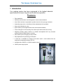
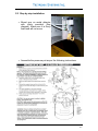
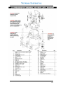
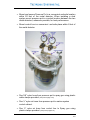
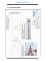
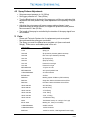
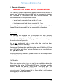
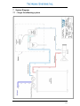
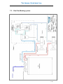
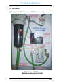
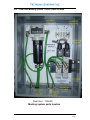
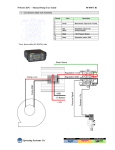
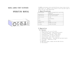
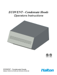
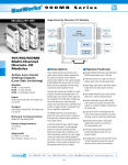
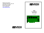
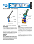
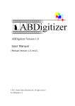
Marking System Operators’ Manual Marking system_manual_rev2.b MARKING SYSTEM User manual (English) Project: Project name Order / Project NO. We would like to take this opportunity to thank you for purchasing your Marking System from Tectronix Systems Inc. The confidence you have placed in our product is sincerely appreciated and we will endeavour to provide the best service possible. Please take the time to read this User Manual completely as this provides you with the expertise necessary to install and adjust the system according to your requirements. In addition to this, you will learn about the sophisticated options provided by our electronics. If, contrary to expectations, you have any problems in the set up and operation of your system, the Tectronix team is available to assist you. 1-2 Copyright The information and data within this document may be amended without notice. Without explicit written permission by TECTRONIX SYSTEMS INC it is prohibited to copy, reproduce or to transfer any part of this document electronically, written media or by any other means 2005 TECTRONIX SYSTEMS INC All rights reserved. 1-3 Index 1 INTRODUCTION ..................................................................................................................1-5 2 GETTING STARTED ............................................................................................................2-6 2.1 2.2 2.3 2.4 2.5 SAFETY: .........................................................................................................................2-6 STEP BY STEP INSTALLATION: ............................................................................................2-7 24VDC CONTROL SIGNAL CONNECTION ............................................................................2-10 OPTIONAL 24VDC POWER SUPPLY ..................................................................................2-11 110VAC CONTROL LINE CONNECTIONS ............................................................................2-12 3 OPERATION:.....................................................................................................................3-13 4 SERVICE: ..........................................................................................................................4-14 4.1 4.2 SPRAY HEAD ADJUSTMENTS:...........................................................................................4-15 SPRAY PATTERN ADJUSTMENT:.......................................................................................4-16 5 PARTS:..............................................................................................................................5-16 6 WARRANTY INFORMATION:............................................................................................6-17 IMPORTANT WARRANTY INFORMATION ..............................................................................6-17 7 SYSTEM DIAGRAM:..........................................................................................................7-18 7.1 7.2 8 : SINGLE GUN MARKING SYSTEM .....................................................................................7-18 : DUAL GUN MARKING SYSTEM ........................................................................................7-19 APPENDIX .........................................................................................................................8-20 8.1 8.2 : SINGLE GUN MARKING SYSTEM 24VDC PARTS LOCATION ................................................8-20 : DUAL GUN MARKING SYSTEM 110VAC PARTS LOCATION .................................................8-21 1-4 1 Introduction Your marking system has been engineered to the highest industrial specifications to ensure long life and trouble free operation. Features • Easy installation • Stainless steel has been used throughout to ensure wear resistance. • An air filter has been incorporated to provide clean air to the spray gun actuator. • Automatic purge valve on the filter provides maintenance free operation. • Heavy duty industrial air valve • Nylon airlines provide high abrasion and environmental resistance. • Push in fittings for air lines and dye lines allow quick and trouble free servicing. • Adjusting marking system location on material accomplished with very accurate software within the Metal Shark™ controller. • Easy cleaning and unclogging of spray nozzle • Easy adjustment of dye density per actuation • A heat belt is available for Pressure Pots when used in cold locations that are subjected to temperatures below 35°F/2°C. • Available with a 24VDC or 110VAC actuation solenoid. • 24VDC power supply option 1-5 2 Getting started 2.1 Safety: This marking system is under air pressure and appropriate precautions must be followed in order to ensure a safe working environment. - This automatic spray gun system should be operated only by an adequately trained operator. Any misuse or handling other than those indicated in this instruction manual is not covered by guarantee or warranty. - Tectronix Systems Inc disclaims all responsibility for any accident or damage caused by failure to observe correct operational and safety procedures as indicated in this manual. - Fluid and solvents can be highly flammable or combustible - Use in well ventilated area - Avoid any ignition sources such as smoking, open flames, electrical hazard, etc. - Never point gun in the direction of the human body or place any part of the human body in front of the gun. - Never exceed the maximum safe working pressure of the equipment - Always release air and disassembling or servicing. fluid pressure before cleaning, - Never modify any part of this system unless authorized to do so in writing by Tectronix Systems Inc. 2-6 2.2 Step by step installation: • Mount gun on metal detector with parts provided (See diagram). Make sure it is firmly fixed and will not move. • Assemble the pressure pot as per the following instructions. 2-7 2-8 • Mount and secure Pressure Pot in a convenient and safe location within 20 feet of the metal detector. When installing a dual system mount pressure pot in a central location between the two metal detectors, whenever possible, for best performance • Mount control box in a convenient and safe place within 6 feet of the metal detector • Run 3/8” nylon hose from pressure pot to spray gun using plastic cable clamps provided. (see picture page 2-10) • Run ¼” nylon air hose from pressure pot to marker system control cabinet. • Run ¼” nylon air hose from control box to Spray gun using plastic clamps provided. (see picture page 2-10) 2-9 • Cut and prepare air and dye/ink hoses correctly, straight cut (90deg) with no burrs. • Connect air supply to pressure pot and adjust tank pressure for 1.4 bar (20psi) • Set the air pressure for the control box to 2.7 bar (40psi) 2.3 24VDC control signal connection • Connect the solenoid control signal through an external 24VDC/300ma supply to the METAL SHARK™ control box (see diagram below). 24Volt DC System 2-10 2.4 Optional 24VDC power supply This Power supply is installed in the control box and is pre-wired so that only the 110VAC needs to be connected. 2-11 2.5 110VAC control line Connections • Connect the solenoid control signal through an 110VAC supply to the METAL SHARK™ control box (see diagram below). 110VAC SYSTEM • Complete METAL SHARK™ metal detector Setup and verify that it detects metal and does not false trip. • Test the marking system before you load the dye/ink into the pressure pot by passing metal through the Metal Detector and listening for the HISS of air from the gun during metal detection Important Never put any Body part in front of the Spray gun • Close air supply at pressure pot and release pressure. • Remove pressure pot top and pour in the marking dye. • Close top, secure and turn on the air supply. • Test the system again and verify that the dye/ink mark is on the test piece of metal. Adjust the time delay in the METAL SHARK™ controller if required to align the dye mark. On METAL SHARK™ controller 2-12 Open menu → System menu → Reject menu “delay” (delay for sprayer to come on after detection) “duration” (length of spray mark on log) “contact” (should be set to pulse, if set on “hold”, gun will spray until the detector is reset) 3 Operation: - Load pressure pot with marking dye. - Adjust pressure pot pressure to 1.4 bars (20psi). Adjust operating control pressure to 2.7 bars (40psi) - Turn the nozzle to the spray position - A mark will be sprayed at the location of metal in the material when the METAL SHARK™ metal detector finds metal in the material passing through its aperture.(see 4-2 for fine spray pattern adjustments) 3-13 4 Service: 1. Periodically remove nozzle and clean with appropriate solvent (Frequency depends on how often the spray gun is actuated.) 2. Every six months remove air filter and check for dirt accumulation, clean as necessary, replace filter if required. 3. Replace filter when pressure to the gun begins to drop or gun starts to fire intermittently. 4. Check for air and dye leaks daily. 5. Test marker weekly as required to maintain reliability. 4-14 4.1 Spray head Adjustments: 4-15 4.2 Spray Pattern Adjustment: • • • • • Set pressure pot pressure to 1.4 (20 lbs) Set trigger pressure to 2.7 bar,(40 lbs) Turn the Black knob at the back of the spray gun until the gun activates.(this adjustment can also produce vary small adjustment to the quantity of ink per spray) Adjusting the pot pressure will cause a spray pattern change. Lower pressure causes a smaller pattern, the higher the pressure a wider pattern. Never exceed 3.5 bar (50 lbs) The length of the spray is controlled by the duration of the spray signal from the controller. 5 Parts: - Please call Tectronix Systems Inc for replacement parts as required. Never dismantle the spray gun or solenoid The Spray gun must be replaced as a complete unit (less nozzle and fittings). There are no serviceable parts in this unit. Part Number Description L-A10 Spray gun L043-005 Zip tip seal kit (includes gasket L043-008) L043-009 tube of 8x nylon Gaskets (L043-008) L043-154 Zip Tip Spray tip L043-001 Spray tip housing L011-075 Pressure Pot 2.25 gal L011-082 Pressure Pot 5 gal QRTN25NA-XX ¼” Nylon Air hose QRTN38NA-XX 3/8” Nylon Dye/INK Hose L12BA452B000061 Air Valve Solenoid EKF22B-02A Air Filter DMM-A01 Marking system SS Mount (C/W hardware) DMK-A01 Single Gun Cabinet C/W Solenoid and Filter DMK-A02 Dual Gun Cabinet C/W Solenoid and Filter 1N105-308-022 3/8” FM Fitting 1N105-308-021 3/8” ML Fitting 1N105-104-021 ¼” FM Fitting 1N105-104-020 ¼” ML Fitting 1N105-104-000 ¼” ML “t” Fitting 1N105-104-021 ¼” Bulkhead Fitting 39272 Tank Heater band (1 for 2.25 gal, 2 for 5 gal) MD-4L-2004 Marking Ink , Case (4 x 4l bottles) L12BA452B000061 24VDC Solenoid L12BA452O000030 110VAC Solenoid PS5R-A24 110VAC to 24VDC, 7.5W Regulated Power Supply 5-16 6 Warranty Information: IMPORTANT WARRANTY INFORMATION Your marking system is warranted against manufactures defects in material and or workmanship provided that the equipment is installed and operated in accordance with the recommendations and instructions written in this operator’s manual • Spray head is warranted for a period of 1 years. • Electrical solenoid and filter is warranted for 1 year Tectronix will repair or replace, at its option, defective parts without charge. Shipping charges will be the responsibility of the owner Marking Ink The 'Marking Ink' supplied with your system has been specially formulated for use with the spray gun and has special lubrication, temperature and high flash point (drying) additives to ensure long gun life and trouble free operation. Use of any marking ink, dye or paint other than what has been supplied may void your Warranty. Replacement Marking Ink is available by the case of 4 bottles of 4 litres each (1US gallon each) from Tectronix Systems Inc. or your distributor. Use p/n MD-4L-2004. Should you have any questions, please contact our service department or sales department Cold Weather When the marking system is to be used in an installation where the temperature falls below 35°Fahrenheit/2°Celsius, heat tape must be installed around the dye/ink supply lines and spray gun. We recommend our special Heat Belts for the pressure pots (see parts list for ordering information). This will prevent the ink from gelling in cold weather and clogging the spray head nozzle 6-17 7 System Diagram: 7.1 : Single Gun Marking system 7-18 7.2 : Dual Gun Marking system 7-19 8 APPENDIX 8.1 : Single Gun Marking system 24VDC parts location Single Gun – 24VDC Marking system parts location 8-20 8.2 : Dual Gun Marking system 110VAC parts location Dual Gun - 110VAC Marking system parts location 8-21 + TECTONIX SYSTEMS INC. th Unit 9 – 18812 96 Ave. Surrey, BC Canada Tel.: (604) 607-6028 Fax.: (604) 607-6026 Internet: www.metal-shark.com User manual: dye marker_june-06_english.doc Status: June 2008 8-22