1
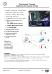
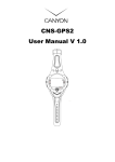
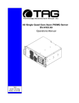
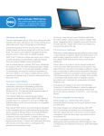
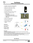
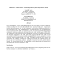
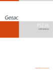
TC-100 “COMMANDER” Operations Manual
TAG
22355 TAG Way
Dulles, VA 20166
Operations Manual
1 Copyright © 2008 Technology Advancement Group®, Inc.
(TAG®)
All rights reserved. This publication and its contents are proprietary to TAG. No part of
this publication may be reproduced in any form or by any means without the written
permission of TAG, 22355 TAG Way, Dulles, Virginia 20166-9310.
TAG has made every effort to ensure the correctness and completeness of the material
in this document. TAG shall not be liable for errors contained herein. The information in
this document is subject to change without notice. TAG makes no warranty of any kind
with regard to this material, including, but not limited to, the implied warranties of
merchantability and fitness for a particular purpose.
1.1
Trademarks
All trademarks, marks, names, or product names referenced in this publication are the
property of respective owners, and TAG neither endorses nor otherwise sponsors any
such products or services referred to herein.
TC-100 “COMMANDER”
Part Number: 1008195 - 1008509
Version 1.3. 03/29/2010
Page 2 of 78
Operations Manual
2 About TAG
2.1.1 Summary of Qualifications
TAG has served as a leading provider of IT solutions to DoD customers over the past
20+ years and has a long-standing and respected history of providing Systems
Engineering, Electronic Equipment and Program Management support to US Military
warfighters. Headquartered in Dulles, Virginia, TAG’s state-of-the-art 35,000 sq. ft.
engineering and manufacturing facility provides all the infrastructure, equipment, and
manpower necessary to engineer, design, test, manufacture, and certify products to the
rugged requirements of the tactical combat theater. Our facilities in Dulles, VA, San
Diego, CA, and St. Louis, MO, allow for rapid deployment of products and support
across the globe.
TAG quickly, efficiently, and cost-effectively tailors rugged solutions for large DoD
programs with specific MIL-STD requirements. TAG’s comprehensive Quality
Assurance (QA) policy – enforced through application of our UL-registered ISO
9001:2000 certified processes – enables TAG to rapidly deploy systems and solutions
that reliably withstand the stresses of the tactical environment. Today, there are over
20,000 TAG systems deployed across various weapons platforms throughout the US
Military. TAG effectively balances all corporate assets – our people, expertise,
infrastructure, and experience – to consistently and successfully execute and deliver to
the DoD.
TAG’s success lies in focusing on the
corporate Mission Statement and leveraging
the tenets of our business model to ensure
the customer’s expectations are exceeded
throughout lengthy program lifecycles.
TAG’s Mission is to resolve our customers’ IT challenges with World‐Class: • Engineering; • Manufacturing and Integration; and • Lifecycle Management
TAG has a proven track record in
implementing these tenets to serve as a trusted advisor to our Government customers.
TAG uses this foundation to ensure risk is mitigated, expectations are exceeded, and
the customer can consistently rely on the company, our equipment, and our services.
TC-100 “COMMANDER”
Part Number: 1008195 - 1008509
Version 1.3. 03/29/2010
Page 3 of 78
Operations Manual
2.1.2 Core Competences
2.1.3 Engineering
TAG’s engineering methodology is built upon Multi-Disciplinary Optimization (MDO) and
rigorous design reviews. Although PMs drive the schedule at TAG, Engineering
leverages Computer-Aided Design (CAD) tools, Computational Fluid Dynamics (CFD)
models, rapid prototyping processes, and diverse test equipment and facilities to ensure
requirements are being met at every step of the design. TAG Engineering follows a
proven design-review process, ensuring all entrance and exit criteria are met at each
stage. Rigorous documentation is compiled to demonstrate requirement compliance,
risks are mitigated, and decisions are prudent – throughout the design process.
TAG prides itself on its engineering
laboratories and facilities. Over the past
three years, TAG has invested in several
pieces of equipment that allow TAG to test
and certify products directly onsite to the
harshest environmental requirements of
military standards – including the MIL-STD810F and DO 160D.
TAG’s onsite test equipment currently
includes a Highly Accelerated Lifecycle
Testing (HALT) Chamber, an Electromagnetic
Interference (EMI) test chamber, and a high-/low-temperature thermal test chamber.
TAG’s facility also provides:
•
Floor plan designed to support a cellular manufacturing model with modular
assembly lines
•
A dedicated 24-hour system burn-in room
•
A modern production status tracking and Enterprise Resource Planning (ERP)
system with external web collaboration capabilities
•
Dedicated Quality Assurance workstations for system compliance and validation
inspection
2.1.4 Manufacturing and Integration
TAG implements Cellular Manufacturing processes through our compartmentalized,
state-of-the-art production facility to minimize waste byproducts and maximize
production efficiency. TAG’s manufacturing facility is physically partitioned to model the
major philosophies of Lean Manufacturing. Consistent with the model, each of TAG’s
production cells are capable of operating in isolation; however personnel and tools are
shared across all cells to streamline manufacturing operations, costs, and the
TC-100 “COMMANDER”
Part Number: 1008195 - 1008509
Version 1.3. 03/29/2010
Page 4 of 78
Operations Manual
production/integration schedule. TAG’s floor technicians are cross-trained in multiple
disciplines so they can be redistributed to any cell that encounters production
bottlenecks, which ensures optimal efficiency.
2.1.5 Lifecycle Management
TAG’s world-class Program Management discipline models the renowned
methodologies of the Project Management Institute (PMI) to ensure successful
completion of the task at hand. Our Program Managers (PMs) serve as the voice of the
customer – driving requirements to which the rest of TAG’s organization answers. As
an explicit tenet of TAG’s corporate mission statement, the PMs not only track cost,
schedule, and technical compliance throughout a project’s period of performance, but
also ensure the customer is supported well beyond it.
TC-100 “COMMANDER”
Part Number: 1008195 - 1008509
Version 1.3. 03/29/2010
Page 5 of 78
Operations Manual
Document Revision History
Date
07/08/2008
08/18/2009
03/290/2010
Version
Number
1.0
1.1
1.3
Updated By
Alan Huckerby
Alan Huckerby
Alan Huckerby
TC-100 “COMMANDER”
Part Number: 1008195 - 1008509
Version 1.3. 03/29/2010
Description of
Changes
Author
Author
Author
Page 6 of 78
Operations Manual
3 About This Manual
3.1.1 Scope and Audience
This Manual provides an introductory overview
of the TC-100 “Commander”. The TC-100 sets
the standard for Ultra Mobile Devices (UMD)
with state-of-the-art technology. The newest
rugged Ultra Mobile PC (UMPC”) can stand up
to the harshest environments, and is designed
specifically to be fully customized to support
unique, mission-critical applications.
3.1.2 Organization
This manual is divided into the following
chapters:
•
•
•
Chapter 1 provides Cautions and Warnings.
Chapter 2 provides operational information.
Chapter 3 Contains all relevant Procedures
and TC-100 “COMMANDER” components.
TC-100 “COMMANDER”
Part Number: 1008195 - 1008509
Version 1.3. 03/29/2010
Page 7 of 78
Operations Manual
Table of Contents
Contents
1 Copyright © 2008 Technology Advancement Group®, Inc. (TAG®) ............................ 2 1.1 Trademarks ............................................................................................................ 2 2 About TAG ................................................................................................................... 3 2.1.1 Summary of Qualifications ................................................................................ 3 2.1.2 Core Competences ........................................................................................... 4 2.1.3 Engineering ....................................................................................................... 4 2.1.4 Manufacturing and Integration........................................................................... 4 2.1.5 Lifecycle Management ...................................................................................... 5 3 About This Manual ....................................................................................................... 7 3.1.1 Scope and Audience ......................................................................................... 7 3.1.2 Organization ...................................................................................................... 7 4 Safety Instructions ....................................................................................................... 13 4.1 Types of Warnings Used In This Manual ................................................................ 13 4.1.1 Safety Symbols and Labels ............................................................................... 13 4.1.2 Conventions ...................................................................................................... 13 5 TC-100 “Commander” Overview .................................................................................. 16 5.1.1 Product Information ........................................................................................... 16 5.1.2 TC-100 “COMMANDER” ................................................................................... 17 5.1.3 Rugged Ultra-Mobile PC (UMPC) Specifications .............................................. 17 5.1.4 Com Port Settings ............................................................................................. 19 5.1.5 TC-100 “COMMANDER” Components .............................................................. 20 5.2 Solid State Power Supply ....................................................................................... 21 5.2.1 Power Management .......................................................................................... 21 6 Procedures .................................................................................................................. 24 6.1.1 “Commander” Power Up ................................................................................... 24 6.1.2 “Commander” Power Down ............................................................................... 24 6.1.3 To operate ‘Commander’ in Night Vision Mode (NVIS) ..................................... 24 6.1.4 Using the On-screen Keyboard ......................................................................... 26 6.1.5 Using the Bluetooth® Wireless Feature (Optional)............................................ 26 6.1.6 Connecting to Another Bluetooth Device .......................................................... 27 6.1.7 Using ExpressCards (depending on your model) .............................................. 31 6.1.8 ExpressCard Type ............................................................................................ 31 6.1.9 Inserting and Removing an ExpressCard .......................................................... 32 6.1.10 TC-100 Mini Port Replicator ............................................................................ 33 6.1.11 TC-100 Attach Port Replicator ........................................................................ 33 6.1.12 TC-100 Remove Port Replicator ..................................................................... 33 6.1.13 TC-100 Stylus ................................................................................................. 34 6.1.14 Battery Removal ............................................................................................. 35 6.1.15 TC-100 GPS ................................................................................................... 36 TC-100 “COMMANDER”
Part Number: 1008195 - 1008509
Version 1.3. 03/29/2010
Page 8 of 78
Operations Manual
6.1.16 TC-100 Com Port Configuration ...................................................................... 37 7 Identifying Components Using Device Manager .......................................................... 41 7.1.1 Working with Device Properties ........................................................................ 44 7.2 Installing and Removing Hardware in Windows...................................................... 46 7.2.1 Using the Add New Hardware Wizard ............................................................... 47 7.3 Installing Legacy Peripherals .................................................................................. 48 7.3.1 Removing Legacy Peripherals .......................................................................... 48 8 BIOS ............................................................................................................................ 51 8.1.1 TAG Approved BIOS ......................................................................................... 51 8.1.2 Common BIOS Settings .................................................................................... 51 8.1.3 AMI BIOS 08.00.15 ........................................................................................... 54 TC-100 “COMMANDER”
Part Number: 1008195 - 1008509
Version 1.3. 03/29/2010
Page 9 of 78
Operations Manual
List of Figures
Figure 5-1 TC-100 “COMMANDER” .............................................................................. 17 Figure 5-2 TC-100 “COMMANDER” Components and Connectors (Front View) .......... 20 Figure 5-3 TC-100 “COMMANDER” Components and Connectors (Top View) ............ 20 Figure 5-4 TC-100 “COMMANDER” Mini Port Replicator and Connectors (Side View) 21 Figure 5-5 TC-100 “COMMANDER” Mini Port Replicator (Docking Connection) .......... 21 Figure 5-6 Power Supply ............................................................................................... 22 Figure 6-1 Software Keyboard ...................................................................................... 26 Figure 6-2 System Tray ................................................................................................. 27 Figure 6-3 Add New Connection ................................................................................... 28 Figure 6-4 Select Device ............................................................................................... 28 Figure 6-5 Wireless Transfer. ........................................................................................ 30 Figure 6-6 Express Card Types .................................................................................... 31 Figure 6-7 Commander showing Express card slot. ...................................................... 32 Figure 6-8 TC-100 Mini Port Replicator ......................................................................... 33 Figure 6-9 TC-100 Stylus and Port Replicator Removal................................................ 34 Figure 6-10 Batteries Removed From Commander....................................................... 35 Figure 6-11 GPS Antenna Location .............................................................................. 36 Figure 6-12 Main Screen ............................................................................................... 37 Figure 6-13 GPSDiag.exe Icon. .................................................................................... 37 Figure 6-14 General Options Screen............................................................................. 38 Figure 6-15 Baud Rate Menu ........................................................................................ 39 Figure 6-16 COM2 Selected .......................................................................................... 40 Figure 7-1 Control Panel ............................................................................................... 41 Figure 7-2 System Properties ........................................................................................ 42 Figure 7-3 Device Manager ........................................................................................... 42 Figure 7-4 Device Manager ........................................................................................... 44 Figure 7-5 Properties Dialog Box .................................................................................. 45 Figure 7-6 Control Panel ............................................................................................... 47 Figure 7-7 Add Hardware Wizard .................................................................................. 47 Figure 7-8 Control Panel ............................................................................................... 48 Figure 7-9 System Properties ........................................................................................ 49 Figure 7-10 Device Manger ........................................................................................... 49 Figure 8-1 Main BIOS Screen ....................................................................................... 54 Figure 8-2 CPU Configuration ....................................................................................... 54 Figure 8-3 Configure Advanced CPU Settings Screen (Top Half). ................................ 55 Figure 8-4 Configure Advanced CPU Settings Screen. ................................................. 55 Figure 8-5 Disable DTS Based Thermal Management. ................................................. 56 Figure 8-6 Max CPUID Value Limit Screen. .................................................................. 56 Figure 8-7 Max C State Screen. .................................................................................... 57 Figure 8-8 IDE Configuration ......................................................................................... 57 Figure 8-9 ATA/IDE Configuration ................................................................................. 58 Figure 8-10 Super IO Configuration. ............................................................................. 58 TC-100 “COMMANDER”
Part Number: 1008195 - 1008509
Version 1.3. 03/29/2010
Page 10 of 78
Operations Manual
Figure 8-11 Serial Port 1 Address Screen. .................................................................... 59 Figure 8-12 ACPI Configuration Screen. ....................................................................... 59 Figure 8-13 ACPI Version Features .............................................................................. 60 Figure 8-14 General ACPI Configuration....................................................................... 60 Figure 8-15 General ACPI Configuration Screen. ......................................................... 61 Figure 8-16 General ACPI Configuration....................................................................... 61 Figure 8-17 ACPI Settings Screen. ............................................................................... 62 Figure 8-18 Advanced ACPI Configuration Screen. ...................................................... 62 Figure 8-19 ACPI Settings Screen. ............................................................................... 63 Figure 8-20 South Bridge ACPI Configuration Screen. ................................................. 63 Figure 8-21 Advanced Settings Screen. ........................................................................ 64 Figure 8-22 MPS Revision Screen. ............................................................................... 64 Figure 8-23 Advanced Settings Screen. ........................................................................ 65 Figure 8-24 PCI Express Configuration Screen. ........................................................... 65 Figure 8-25 Advanced Settings Screen. ........................................................................ 66 Figure 8-26 Smbios Configuration Screen. ................................................................... 66 Figure 8-27 Advanced Settings Screen. ........................................................................ 67 Figure 8-28 Configure Remote Access Type and Parameters Screen. ......................... 67 Figure 8-29 Advanced Settings Screen. ........................................................................ 68 Figure 8-30 USB Configuration Screen. ........................................................................ 68 Figure 8-31 Advanced Settings Screen. ........................................................................ 69 Figure 8-32 Trip Points for DIS Screen. ........................................................................ 69 Figure 8-33 Advanced PCI/PnP Settings Screen. ......................................................... 70 Figure 8-34 Advanced PCI/PnP Settings Screen. ......................................................... 70 Figure 8-35 South Bridge Configuration Screen ............................................................ 71 Figure 8-36 Boot Settings Configuration Screen. .......................................................... 71 Figure 8-37 Boot Settings Configuration Screen. .......................................................... 72 Figure 8-38 Boot Settings Configuration Screen. .......................................................... 72 Figure 8-39 Security Settings Screen. ........................................................................... 73 Figure 8-40 Advanced Chipset Settings Screen. ........................................................... 73 Figure 8-41 North Bridge Chipset Configuration Screen. .............................................. 74 Figure 8-42 Boot Display Configuration Screen. ........................................................... 74 Figure 8-43 Boot Display Configuration Screen. ........................................................... 75 Figure 8-44 Advanced Chipset Settings Screen. ........................................................... 75 Figure 8-45 South Bridge Chipset Configuration Screen............................................... 76 Figure 8-46 Save Changes and Exit Screen. ................................................................ 76 Figure 8-47 Exit Screen................................................................................................. 77 List of Tables
Table 5-1 TC-100 Commander Specifications .............................................................. 19 Table 6-1 Bluetooth Settings. ........................................................................................ 27 Table 6-2 Wireless File Transfer ................................................................................... 29 TC-100 “COMMANDER”
Part Number: 1008195 - 1008509
Version 1.3. 03/29/2010
Page 11 of 78
Chapter 1
Chapter 1
Cautions and Warnings.
Electronically distributed. Subject to user discretion when printed.
TC-100 “COMMANDER”
Part Number: 1008195 - 1008509
Version 1.3. 03/29/2010
Page 12 of 78
Operations Manual
4 Safety Instructions
4.1
Types of Warnings Used In This Manual
Read this manual thoroughly, paying special attention to the caution and
warnings.
4.1.1 Safety Symbols and Labels
DANGER
WARNING
CAUTION
These warnings and
cautions indicate situations
or practice that might
result in property damage.
4.1.2 Conventions
4.1.2.1 Important Messages
Important messages appear where
mishandling of components is possible or when
work orders can be misunderstood. These
messages also provide vital information
associated with other aspects of system
operation. The word “important” is written as
“IMPORTANT,” both capitalized and bold and
is followed by text in italics. The italicized text
is the important message.
4.1.2.2 Warnings
Warnings appear where overlooked details
may cause damage to the equipment or result
in personal injury. Warnings should be taken
seriously. Warnings are easy to recognize. The
word “warning” is written as “WARNING,” both
TC-100 “COMMANDER”
Part Number: 1008195 - 1008509
Version 1.3. 03/29/2010
Page 13 of 78
Operations Manual
capitalized and bold and is followed by text in
italics. The italicized text is the warning
message.
4.1.2.3 Cautions
Cautionary messages should also be heeded
to help you reduce the chance of losing data or
damaging the system. Cautions are easy to
recognize. The word “caution” is written as
“CAUTION,” both capitalized and bold and is
followed by text in italics. The italicized text is the
cautionary message.
4.1.2.4 Notes
Notes inform the reader of essential but noncritical information. These messages should be
read carefully as any directions or instructions
contained therein can help you avoid making
mistakes. Notes are easy to recognize. The
word “note” is written as “NOTE,”
TC-100 “COMMANDER”
Part Number: 1008195 - 1008509
Version 1.3. 03/29/2010
Page 14 of 78
Chapter 2
Chapter 2
TC-100 “COMMANDER”.
Electronically distributed. Subject to user discretion when printed.
TC-100 “COMMANDER”
Part Number: 1008195 - 1008509
Version 1.3. 03/29/2010
Page 15 of 78
Operations Manual
5 TC-100 “Commander” Overview
5.1.1 Product Information
The TC-100 “Commander” sets the standard
for Ultra Mobile Devices (UMD) with state-ofthe-art technology. The newest rugged Ultra
Mobile PC (UMPC) can stand up to the
harshest environments, and is designed
specifically to be fully customized to support
unique, mission-critical applications.
•
•
•
•
•
•
•
•
•
Light, Small Footprint Chassis, <4lbs (fits
in a pocket).
The TC-100 Commander does not use
dissimilar metals in its construction.
Integrated GPS for Satellite Navigation.
Steaming Video Feed for live data.
Sunlight Readability and Reduced Glare
for use in the battle field.
Touch Screen Display.
Mobile Communication and Data
(situational awareness).
Dual Hot Swappable Batteries (extend
operations without interrupting power).
Customizable Button Boards for easy
application.
Your system may contain components not
described in this User Manual. For detailed
information on these components, refer to the
manufactures website or contact TAG
Technical Support at [email protected].
TC-100 “COMMANDER”
Part Number: 1008195 - 1008509
Version 1.3. 03/29/2010
Page 16 of 78
Operations Manual
5.1.2 TC-100 “COMMANDER”
Figure 5-1 TC-100 “COMMANDER”
Chassis Dimensions Weight Mounting/Carrying Processor(s) Chipset Memory Storage Storage Encryption Video Capture Audio Controls & Indicators Pointing Device Keyboard 5.1.3 Rugged Ultra-Mobile PC (UMPC)
Specifications
Ergonomically Designed, Conduction‐Cooled Aluminum Chassis 10.55" W x 5.82" H x 1.99" D 3.8lbs w/Batteries; 2.6lbs w/out Batteries Optional Vehicle Mount, Kneeboard, Hand Strap, Shoulder Strap Intel® Atom Z530. 1.6 GHz Intel® SCH 1GB DDR2 Removable 1.8” Solid State Hard Drive (Optional Capacities Available) Optional 128, 192 or 256‐bit SATA to SATA Encryption Engine (Available Q1 2010) NIST and CSE Certified Hardware AES (Advanced Encryption Standard) Algorithm Composite NTSC/PAL/SECAM (Option Available Q1 2010) External Headphone/Microphone Input; Single Speaker (10) Customizable Buttons Directional Pad (D‐Pad) Mouse Optional Keyboard TC-100 “COMMANDER”
Part Number: 1008195 - 1008509
Version 1.3. 03/29/2010
Page 17 of 78
Operations Manual
Power Supply Battery Battery Life Operating System SD Card Slot SIMM Card Slot User Expansion Options Display Size Screen Type Resolution Brightness Contrast Ratio Viewing Angle Backlight Color Support Sunlight Readable NVIS, NVG Compatible WLAN WPAN System Antennas GPS USB 2.0 Power Audio Line Out Standard Port Replicator (2) USB 2.0 (1) 15‐16 VDC Power Input (1) 10/100/1000 Ethernet (1) 2.5mm Audio Port AC/DC Adapter (100‐120VAC, 200‐240VAC Input,50‐60Hz 15VDC 3.67A Output) Dual Hot‐Swappable 34Whr Batteries Up to 8 Hrs Supports Microsoft Windows® and Linux® (Contact Sales Rep for Options) (1) on Commander (1) on Commander (Applicable when configured with GSM Interface) (1) PCMCIA/Cardbus Slot OR (1) Express Card 34/54 Slot 7” Widescreen Display Resistive Touch Screen 1024 x 600 250 cd/m² 400:1 140° (H) 110° (V) LED True Color Standard Optional 802.11b/g (802.11n Optional) Bluetooth Functionality (Standard On Certain Configuration) Dual Integrated WLAN/WPAN Antennas Single Integrated GPS Powered Helical Antenna GPS, External Antenna May Be Required For In‐Vehicle Operation (1) on Commander Unit (1) 15‐16 VDC Input (1) 2.5mm Audio Port Vertical Port Replicator (Optional) (2) USB 2.0 (1) 15‐16 VDC Power Input (1) 10/100/1000 Ethernet (1) Audio Input/Output (Through Micro‐D Connector) (1) Serial Port (Through Micro‐D Connector) TC-100 “COMMANDER”
Part Number: 1008195 - 1008509
Version 1.3. 03/29/2010
Page 18 of 78
Operations Manual
(1) Video Input (Through Micro‐D Connector) Table 5-1 TC-100 Commander Specifications
5.1.4 Com Port Settings
• The GPS UART Interface has a bit rate range
of 1.2kbps to 115.2 kbps.
Protocol options for the GPS
•
•
NMEA, SiRFBINARY™, and AI3/F.
Default setting for the GPS UART Interface is
Com2, 9.6 kbps/NMEA Protocol.
GPS Features
•
GPS technology based upon by the SiRF
Technologies™ SiRFStar III™
•
UART interface
•
Fast acquisition time and high sensitivity GPS
Receiver
•
Ultra-low power consumption.
•
Surface Mount Design (SMD)
•
20 channel GPS receiver
•
Multi-path Mitigation
•
Uses NAVSTAR GPS L1 C/A signal
•
SBAS (WAAS, ENGOS and MSAS) support
•
Available Software accelerator for improved
sensitivity: Satellite acquisition and
•
tracking
•
Format Selectable Output Data: NMEA,
SiRFBinary™ and AI3/F
•
Compatible with SiRF Technologies GSW3
Software
TC-100 “COMMANDER”
Part Number: 1008195 - 1008509
Version 1.3. 03/29/2010
Page 19 of 78
Operations Manual
5.1.5 TC-100 “COMMANDER” Components
This section provides an overview of the most
common components installed in the TC-100
“COMMANDER.” Information is also provided
on how to identify specific components within
your TC-100 “COMMANDER”. For detailed
information on the specific components
installed, refer the manufactures website.
Figure 5-2 TC-100 “COMMANDER” Components and Connectors (Front View)
NOTE: Simm Card, is used in conjunction with optional 3G modems.
Figure 5-3 TC-100 “COMMANDER” Components and Connectors (Top View)
TC-100 “COMMANDER”
Part Number: 1008195 - 1008509
Version 1.3. 03/29/2010
Page 20 of 78
Operations Manual
Figure 5-4 TC-100 “COMMANDER” Mini Port Replicator and Connectors (Side View)
Figure 5-5 TC-100 “COMMANDER” Mini Port Replicator (Docking Connection)
5.2
Solid State Power Supply
5.2.1 Power Management
Modern motherboards provide Advanced
Configuration and Power Management
Interface (ACPI) settings such as wake-up,
power button function and standby/suspend
timers. These functions are configured in the
CMOS Setup.
TC-100 “COMMANDER”
Part Number: 1008195 - 1008509
Version 1.3. 03/29/2010
Page 21 of 78
Operations Manual
Figure 5-6 Power Supply
5.2.1.1 Power Supply Specifications •
AC/DC Adapter (120VAC Input, 16VDC 4.0A
Output)
•
Dual Hot-Swappable 34Whr batteries.
1
Estimated battery life 8hrs
TC-100 “COMMANDER”
Part Number: 1008195 - 1008509
Version 1.3. 03/29/2010
Page 22 of 78
Operations Manual
Chapter 3
Procedures.
Electronically distributed. Subject to user discretion when printed.
TC-100 “COMMANDER”
Part Number: 1008195 - 1008509
Version 1.3. 03/29/2010
Page 23 of 78
Operations Manual
6 Procedures
The procedures within this Chapter contain
relevant information to ensure the TC-100
“COMMANDER” maintains its maximum
performance potential.
6.1.1 “Commander” Power Up
Check to make sure that all the cables are
seated and connected correctly to the back of
the unit such as, mouse, monitor VGA cable
and both power cables. (If equipped). In the
most common use case, the unit will be used in
stand-alone mode, without a, mouse, monitor
or power cable.).
Power Up
1. Press Power Button then turn Brightness UP
NOTE: If unit is to use battery power the
batteries must be charged (If batteries are
to low unit must be plugged in to the
external power supply to power on.
6.1.2
“Commander” Power Down
Soft Shutdown
1. At Windows Start Menu Select Shut Down.
2. Select Shut Down from the drop down menu
and press OK.
Hard Shut Down
1. Hold Down Power Button within Windows
this will Shut Down All.
NOTE: Ensure that LED’s are off otherwise
they will drain the battery).
6.1.3 To operate ‘Commander’ in Night Vision
Mode (NVIS)
1. Commence with the ‘Commander’ turned on in
normal operating mode
TC-100 “COMMANDER”
Part Number: 1008195 - 1008509
Version 1.3. 03/29/2010
Page 24 of 78
Operations Manual
2. Turn the contrast all the way DOWN, This
action will place the “Commander “in the NVIS
Mode of operation.
3. To return to normal operational mode turn the
contrast all the way UP.
TC-100 “COMMANDER”
Part Number: 1008195 - 1008509
Version 1.3. 03/29/2010
Page 25 of 78
Operations Manual
6.1.4 Using the On-screen Keyboard
Use the on-screen keyboard to enter text and
perform various keyboard functions.
1. Click the on-screen keyboard icon.
located on the Windows system tray and the
software keyboard will appear onscreen.
Figure 6-1 Software Keyboard
2. Tap the characters on the on-screen keyboard
with the touchscreen digitizer pen.
NOTE: To protect the LCD display, use the
touchscreen or digitizer pen on your
touchscreen.
6.1.5 Using the Bluetooth® Wireless Feature
(Optional)
Depending on your model, your tablet PC may
incorporate the Bluetooth capability for shortrange (about 10 meters) wireless
communications between devices without
requiring a cable connection. With Bluetooth,
data can be transmitted through walls, pockets
and briefcases as long as two devices are
within range. By default, the Commander
Bluetooth feature is active (always ON) upon
booting the Commander and is in the general
discoverable and pairable mode.
The status of the Bluetooth connection is
indicated by the Bluetooth icon located in the
system tray in the lower-right part of the
screen.
TC-100 “COMMANDER”
Part Number: 1008195 - 1008509
Version 1.3. 03/29/2010
Page 26 of 78
Operations Manual
Figure 6-2 System Tray
You can use the Bluetooth Utility to configure
Bluetooth connection settings and transfer
files.
6.1.6 Connecting to Another Bluetooth Device
1. Make sure that the target Bluetooth device is
turned on, discoverable and within close range.
(See the documentation that came with the
Bluetooth device.)
Right-click (press lightly until a pop-up menu
appears) the icon,
and then click Add New Connection.
Table 6-1 Bluetooth Settings.
TC-100 “COMMANDER”
Part Number: 1008195 - 1008509
Version 1.3. 03/29/2010
Page 27 of 78
Operations Manual
2. The Add New Connection Wizard window
appears. Select Express Mode
(Recommended), and then click Next.
Figure 6-3 Add New Connection
3. Select the device to connect to and click Next.
Figure 6-4 Select Device
TC-100 “COMMANDER”
Part Number: 1008195 - 1008509
Version 1.3. 03/29/2010
Page 28 of 78
Operations Manual
Depending on the type of Bluetooth device that
you want to connect to, you will need to enter
the pertinent information.
Sending a File
4. Make sure that the target Bluetooth device is
turned on, discoverable and within close range.
(See the documentation that came with the
Bluetooth device.)
5. Right-click the icon, and then click Wireless
File Transfer.
Table 6-2 Wireless File Transfer
6. In the Wireless File Transfer window, click
Add to browse for the file to send.
TC-100 “COMMANDER”
Part Number: 1008195 - 1008509
Version 1.3. 03/29/2010
Page 29 of 78
Operations Manual
7. Click the target device from the list, and then
click Send to start the transfer procedure.
Figure 6-5 Wireless Transfer.
TC-100 “COMMANDER”
Part Number: 1008195 - 1008509
Version 1.3. 03/29/2010
Page 30 of 78
Operations Manual
6.1.7 Using ExpressCards (depending on your
model)
NOTE: The ExpressCard interface is not
compatible with the PC card interface. You
need optional adapters for using PC cards
if your tablet PC comes with the
ExpressCard slot.
ExpressCard supports the USB 2.0 serial data
interface (supporting speeds of up to 480
Mbps), improving speed in data transfer while
conserving power usage.
6.1.8 ExpressCard Type
The ExpressCard slot can accommodate a 54
mm (ExpressCard/54) or 34 mm
(ExpressCard/34) wide ExpressCard. Typical
ExpressCards support a very extensive range of
applications including memory, wired and
wireless communication cards, and security
devices. Shown next are the appearances of
ExpressCards for your reference.
ExpressCard/54
ExpressCard/34
Figure 6-6 Express Card Types
TC-100 “COMMANDER”
Part Number: 1008195 - 1008509
Version 1.3. 03/29/2010
Page 31 of 78
Operations Manual
6.1.9 Inserting and Removing an ExpressCard
6.1.9.1 Insert an ExpressCard: 1. Locate the ExpressCard slot ( ) on the Top of
the Commander.
2. Slide the ExpressCard, with its label facing up,
all the way into the slot until the rear
connectors click into place
3. When a new card is seated, the tablet PC will
detect it and try to install the appropriate driver.
Follow the on-screen instructions to complete
the process.
Figure 6-7 Commander showing Express card slot.
6.1.9.2 Remove an ExpressCard: 1. Double-click the Safely Remove Hardware
icon found on the Windows XP taskbar and the
Safely Remove Hardware window appears on
screen.
2. Select (highlight) the ExpressCard from the list
to disable the card.
3. Push the ExpressCard slightly to release the
card.
4. Pull the card out of the slot.
TC-100 “COMMANDER”
Part Number: 1008195 - 1008509
Version 1.3. 03/29/2010
Page 32 of 78
Operations Manual
6.1.10 TC-100 Mini Port Replicator
While the Commander has a long battery life of
7+ hours, it can be charged through the miniport replicator. The replicator has unique pins
that easily fit the bottom the Commander with a
secure fastener. The conveniently small,
portable size of the mini-port replicator allows
users to take it on the go and hook up to any
available power source. It also comes with two
(2) USB Ports, One (1) 2.5mm Audio Port and
one (1) Ethernet Connection.
Figure 6-8 TC-100 Mini Port Replicator
6.1.11 TC-100 Attach Port Replicator
1. Turn off all power to the Port Replicator
2. Remove all cables
3. Undo the center locking screw
4. Remove Port Replicator in a straight
movement. Do not bend as that will
damage the Port Replicators unique
pins.
6.1.12 TC-100 Remove Port Replicator
1. Push Port Replicator on to the
Commanders pins. Ensure it is the
right way around.
TC-100 “COMMANDER”
Part Number: 1008195 - 1008509
Version 1.3. 03/29/2010
Page 33 of 78
Operations Manual
2. Tighten center locking screw. Use
nominal tightness as over tightening will
damage the Port Replicator.
3. Connect all cables as required.
6.1.13 TC-100 Stylus
The Commander’s responsive touch screen
and high-resolution LCD allow the device to
function as a convenient tool for manipulating
and navigating digital maps. The touch screen
can be operated by gloved fingers or the use of
a stylus. The unit comes equipped with two
styli that are stored at the top of the backside
of the Commander. The distinctive shape
makes them effortless to access and replace
when needed.
Figure 6-9 TC-100 Stylus and Port Replicator Removal
TC-100 “COMMANDER”
Part Number: 1008195 - 1008509
Version 1.3. 03/29/2010
Page 34 of 78
Operations Manual
6.1.14 Battery Removal
The Dual Hot-Swappable 34Whr batteries with
AC/DC Adapter (120VAC Input, 16VDC 4.0A
Output) and an estimated battery life of 8hrs
are removable by releasing the two (2) battery
holdings screws and extracting the batteries
downward out of their casings.
Figure 6-10 Batteries Removed From Commander
TC-100 “COMMANDER”
Part Number: 1008195 - 1008509
Version 1.3. 03/29/2010
Page 35 of 78
Operations Manual
6.1.15 TC-100 GPS
For transmitting or receiving wireless data, the
Commander is equipped by default with
802.11, Bluetooth, and GPS capabilities. The
device can be further customized to support
proprietary wireless communication protocols
for relaying critical intelligence and
reconnaissance data.
Figure 6-11 GPS Antenna Location
TC-100 “COMMANDER”
Part Number: 1008195 - 1008509
Version 1.3. 03/29/2010
Page 36 of 78
Operations Manual
6.1.16 TC-100 Com Port Configuration
Figure 6-12 Main Screen
1. Select GPSDIAG.exe file as highlighted on the
Main Screen and press Enter.(Figure 6-5).
Figure 6-13 GPSDiag.exe Icon.
TC-100 “COMMANDER”
Part Number: 1008195 - 1008509
Version 1.3. 03/29/2010
Page 37 of 78
Operations Manual
2. On the Diagnostics screen scroll across to
Options then on the Drop Down Menu scroll
down to General Options and press Enter.
(Figure 6-6.)
Figure 6-14 General Options Screen.
TC-100 “COMMANDER”
Part Number: 1008195 - 1008509
Version 1.3. 03/29/2010
Page 38 of 78
Operations Manual
3. In the General Options Screen extend the
Baud Rate Menu then scroll down and select
9600. Ensure Relative Time Stamp is
checked then press OK. (Figure 6-7.).
Figure 6-15 Baud Rate Menu
TC-100 “COMMANDER”
Part Number: 1008195 - 1008509
Version 1.3. 03/29/2010
Page 39 of 78
Operations Manual
4. In the GPS Diagnostics screen select COM2.
This command will automatically set up your
system. (Figure 6-8.)
Figure 6-16 COM2 Selected
5. Press Enter to save your settings and Exit.
TC-100 “COMMANDER”
Part Number: 1008195 - 1008509
Version 1.3. 03/29/2010
Page 40 of 78
Operations Manual
7 Identifying Components Using Device Manager
The Device Manager is one of Windows' most
useful diagnostic tools. It lets you see all of the
devices attached to your computer, and which
resources they are each using. To access the
Device Manager do the following:
1. Click Start, point to Settings, and then click
Control Panel. (Figure 7-1).
Figure 7-1 Control Panel
TC-100 “COMMANDER”
Part Number: 1008195 - 1008509
Version 1.3. 03/29/2010
Page 41 of 78
Operations Manual
2. Double-click the System icon in the
Control Panel page to open system
properties. (Figure 7-2).
Figure 7-2 System Properties
3. Click the Hardware tab, and then click the
Device Manager button. (Figure 7-3).
Figure 7-3 Device Manager
TC-100 “COMMANDER”
Part Number: 1008195 - 1008509
Version 1.3. 03/29/2010
Page 42 of 78
Operations Manual
After opening Device Manager, you will see a
list of all the devices Windows detected on
your system. The Device Manager display is
recreated each time the computer is started, or
whenever a dynamic change to the computer
configuration occurs, such as addition of a new
device while the system is running.
NOTE: To include hidden devices, on the
View menu, click Show hidden devices. A
check mark next to Show hidden devices
indicates hidden devices are showing.
Click it again to clear the check mark.
Hidden devices include non-PnP devices
and devices that have been physically
removed from the computer but have not
had their drivers uninstalled.
The devices shown represent the computer's
current hardware configuration information.
Any non-functioning devices are displayed with
an exclamation point, indicating that a problem
exists with the device; disabled devices are
displayed with a small red "x" over the icon.
You can use Device Manager to enable or
disable devices, troubleshoot devices, update
drivers, use driver rollback, and change
resources such as interrupt requests (IRQs)
assigned to devices.
TC-100 “COMMANDER”
Part Number: 1008195 - 1008509
Version 1.3. 03/29/2010
Page 43 of 78
Operations Manual
7.1.1 Working with Device Properties
To display a device's properties do the
following:
1. Access the Device Manager as described in
steps 1 through 3. (Figure 7-4).
Figure 7-4 Device Manager
TC-100 “COMMANDER”
Part Number: 1008195 - 1008509
Version 1.3. 03/29/2010
Page 44 of 78
Operations Manual
2. In the Device manager dialog box (Figure
7-5), double-click the device, or select the
device and then click the Properties
toolbar button.
Figure 7-5 Properties Dialog Box
In the device's Properties dialog box, there
might be several tabs. You can view the status
and configuration information, as well as the
device manufacturer, device type, and location
in the upper portion of the General tab.
The Device status box in the middle of the
General tab displays the status of the device,
including any errors. If the device has any
problems, the Device Status box briefly
describes the problem, and usually describes
the appropriate course of action to correct the
problem.
TC-100 “COMMANDER”
Part Number: 1008195 - 1008509
Version 1.3. 03/29/2010
Page 45 of 78
Operations Manual
3. Click Troubleshoot... to use the built-in
mechanisms for detecting the nature of the
problem.
Other tabs include the Driver tab, which
displays the details of the driver being used.
This tab also lets you update or uninstall the
driver. The Resources tab displays the
hardware resources being used. This tab
allows you to see and resolve any conflicts
caused by non-PnP devices. Along with these
tabs, some devices have additional advanced
settings or tabs for device-specific settings.
7.2
Installing and Removing Hardware in Windows
Plug and Play (PnP) is a standard that makes
installing new hardware devices easier. Prior to
PnP, installing new hardware meant finding
and installing peripheral drivers and making
sure the new device didn't conflict with another
device. Theoretically, if you have a computer
designed for PnP and are using a PnP
operating system (like Windows), installing a
printer, sound card, modem, or other peripheral
is a simple matter of plugging in the device.
It's not always quite this simple. Assuming you
are using a PnP computer, when you attach a
PnP device, you may see a message indicating
that Windows has recognized the new deviceeither immediately or the next time you start up
your system. If Windows needs a driver that is
not currently installed, you may at that point be
asked to insert a disk or the Windows CDROM. If you don't see a message but the
device appears to be working, you can assume
that everything is fine.
TC-100 “COMMANDER”
Part Number: 1008195 - 1008509
Version 1.3. 03/29/2010
Page 46 of 78
Operations Manual
7.2.1 Using the Add New Hardware Wizard
If the device is not working properly, try using
the Add New Hardware Wizard. To run this
wizard, do the following:
1. From the Start menu, point to Settings and
then click Control Panel. (Figure 7-6).
Figure 7-6 Control Panel
2. Double-click the Add Hardware icon. (Figure
7-7).
Figure 7-7 Add Hardware Wizard
TC-100 “COMMANDER”
Part Number: 1008195 - 1008509
Version 1.3. 03/29/2010
Page 47 of 78
Operations Manual
7.3
Installing Legacy Peripherals
When you install what Microsoft calls a legacy
peripheral, you will need to use the Add
Hardware Wizard, as described to let Windows
know about the new device.
7.3.1 Removing Legacy Peripherals
When removing a legacy peripheral from your
system, you need to let Windows know that the
device is gone. This enables Windows to reuse
the resources (places in memory and internal
communications channels) that it previously
allocated to that device.
To tell Windows that you have removed a
legacy device, perform the following steps:
1. From the Start menu, point to Settings and
then click Control Panel. (Figure 7-8).
Figure 7-8 Control Panel
TC-100 “COMMANDER”
Part Number: 1008195 - 1008509
Version 1.3. 03/29/2010
Page 48 of 78
Operations Manual
2. Double-click the System icon. (Figure 7-9).
Figure 7-9 System Properties
3. Click the Hardware tab.
4. Click the Device Manager button. (Figure 710).
Figure 7-10 Device Manger
TC-100 “COMMANDER”
Part Number: 1008195 - 1008509
Version 1.3. 03/29/2010
Page 49 of 78
Operations Manual
5. Click the name of the item you have removed
from your system. If you don't see the item,
look for a category heading that describes the
type of device you removed, and then click the
plus sign to its left to display a list of items in
that category.
6. From the Action menu, click Uninstall.
7. Click OK.
TC-100 “COMMANDER”
Part Number: 1008195 - 1008509
Version 1.3. 03/29/2010
Page 50 of 78
Operations Manual
8 BIOS
8.1.1 TAG Approved BIOS
The BIOS (basic input/output system) is the
program stored on the CMOS that the
Commander uses to get the system started
after you turn it on. The BIOS also manages
data flow between the computer's operating
system and attached devices such as the hard
disk, video adapter, and mouse.
CAUTION: The BIOS installed on your
server was loaded and tested with all the
devices initially installed in your system. If
you desire to have the BIOS updated,
consult TAG technical support in advance
as updates to your approved BIOS may
cause your system to become unstable or
inoperable.
8.1.2 Common BIOS Settings
8.1.2.1 Access BIOS 1. Connect an external Key Board by a USB port.
2. Power UP the “Commander”.
3. Once the system is powered up hit the DEL
Key until the BIOS appears.
4. Verify the settings by scrolling through the
BIOS then on the upper right hand side of the
screen select Save Changes and Exit.
5. The same result can be obtained by using the
short cut keys. Hit ESCAPE a number of times
to bring up a screen where you can either
accept or reject any changes.
TC-100 “COMMANDER”
Part Number: 1008195 - 1008509
Version 1.3. 03/29/2010
Page 51 of 78
Operations Manual
8.1.2.2 Upgrade BIOS WARNING: ADVICE TO UPGRADE YOUR
BIOS CAN BE OBTAINED FROM
CUSTOMER SERVICE AT TAG.COM.
GENERIC BIOS UPGRADE
1. Move BIOS files to a bootable media (User
Defined).
2. Power UP the “Commander”.
3. Boot the TC-100 with an external USB
keyboard. Press F11 to choose the BBS PopUp.
4. Choose the USB stick you inserted.
5. Follow the instructions as detailed by TAG
Customer Service.
8.1.2.3 COM / Serial Port The Commander has two serial ports. (One (1)
on the Port Replicator and one (1) on the
Commander) In the BIOS you can assign
COM1/COM2/COM3/COM4 to serial port 1 or
2.
Most BIOS' also allow you to set the I/O and
IRQ but this is mostly done automatically.
8.1.2.4 Hard Drives Most modern BIOS' allow automatic detection
of disk parameters. The settings can be
individually configured for the primary master
and slave device and the secondary master
and slave device.
8.1.2.5 Boot Sequence This setting is used to control the order that the
BIOS uses during the boot process to look for
a boot device from which to load the operating
system.
TC-100 “COMMANDER”
Part Number: 1008195 - 1008509
Version 1.3. 03/29/2010
Page 52 of 78
Operations Manual
8.1.2.6 Date and Time The Date and Time is set in the BIOS, stored in
CMOS, and maintained by CMOS battery.
8.1.2.7 Plug and Play BIOS Today's BIOS' are Plug and Play (PnP)-aware.
This means they are able to automatically
assign resources such as IRQ and DMA to
PnP devices.
Information about PnP devices is stored in a
separate area of non-volatile CMOS memory,
called the Extended System Configuration
Database (ESCD). Both the PnP BIOS and the
operating system can access this area and
communicate with each other about resource
settings assigned to PnP devices as well as
non-PnP devices. For example, when a fixed
interrupt request (IRQ) is manually assigned to
a particular device using Device Manager,
Windows will write this information to the
ESCD on shutdown thereby preventing the
BIOS from assigning the same IRQ to a PnP
device at startup.
You can also reserve IRQs for non-PnP
devices in the CMOS setup, this will prevent
the BIOS from assigning these reserved
resources to PnP devices, a common example
is a legacy sound card that needs IRQ 5.
8.1.2.8 Power Management Modern motherboards provide Advanced
Configuration and Power Management
Interface (ACPI) settings such as wake-up,
power button function and standby/suspend
timers. These functions are configured in the
CMOS Setup.
TC-100 “COMMANDER”
Part Number: 1008195 - 1008509
Version 1.3. 03/29/2010
Page 53 of 78
Operations Manual
8.1.3 AMI BIOS 08.00.15
1. After hitting Delete when computer is booting
you will be taken to the Main BIOS System
Utility screen. (Figure 8-1)
Figure 8-1 Main BIOS Screen
2. Scroll across to the Advancement tab and
press Enter. Select CPU Configuration and
press Enter. (Figure 8-2.)
Figure 8-2 CPU Configuration
TC-100 “COMMANDER”
Part Number: 1008195 - 1008509
Version 1.3. 03/29/2010
Page 54 of 78
Operations Manual
3. Configure Advanced CPU Settings screen.
(Figure 8-3.)
Figure 8-3 Configure Advanced CPU Settings Screen (Top Half).
4. On the Configure Advanced CPU
Settings screen scroll down and Disable
DTS Calibration. Press Enter. (Figure 84.)
Figure 8-4 Configure Advanced CPU Settings Screen.
TC-100 “COMMANDER”
Part Number: 1008195 - 1008509
Version 1.3. 03/29/2010
Page 55 of 78
Operations Manual
5. On the Configure Advanced CPU Settings
screen scroll down to Disable DTS Based
Thermal Management. Press Enter (Figure 84.)
Figure 8-5 Disable DTS Based Thermal Management.
6. Max CPUID Value Limit screen No Change
(Figure 8-4.)
Figure 8-6 Max CPUID Value Limit Screen.
TC-100 “COMMANDER”
Part Number: 1008195 - 1008509
Version 1.3. 03/29/2010
Page 56 of 78
Operations Manual
7. Max C State screen. No Change. Press
Escape to return to the Main Menu. (Figure 87.)
Figure 8-7 Max C State Screen.
8. On the Main Menu screen scroll down to IDE
Configuration. Press Enter. (Figure 8-8.)
Figure 8-8 IDE Configuration
TC-100 “COMMANDER”
Part Number: 1008195 - 1008509
Version 1.3. 03/29/2010
Page 57 of 78
Operations Manual
9. ATI/IDE Configuration. No Change. Press
Escape to return to the Main Menu. (Figure 89.)
Figure 8-9 ATA/IDE Configuration
10. On the Main Menu screen scroll down to
Super IO Configuration. Press Enter. (Figure
8-10.)
Figure 8-10 Super IO Configuration.
TC-100 “COMMANDER”
Part Number: 1008195 - 1008509
Version 1.3. 03/29/2010
Page 58 of 78
Operations Manual
11. Serial Port 1 Address. No Change. Press
Escape to return to the Main Menu (Figure 811.)
Figure 8-11 Serial Port 1 Address Screen.
12. At the Main Menu scroll down to ACPI
Configuration. Press Enter. (Figure 8-12.)
Figure 8-12 ACPI Configuration Screen.
TC-100 “COMMANDER”
Part Number: 1008195 - 1008509
Version 1.3. 03/29/2010
Page 59 of 78
Operations Manual
13. At the ACPI Settings screen press
ACPI Configuration. (Figure 8-13.)
General
Figure 8-13 ACPI Version Features
14. At the General ACPI Configuration screen.
Scroll down to Repost Video on S3 Resume.
Press Enter.(Figure 8-14.)
Figure 8-14 General ACPI Configuration.
TC-100 “COMMANDER”
Part Number: 1008195 - 1008509
Version 1.3. 03/29/2010
Page 60 of 78
Operations Manual
15. At the Drop Down menu on the General ACPI
Configuration screen select YES and press
Enter(Figure 8-15.)
Figure 8-15 General ACPI Configuration Screen.
16. At the General ACPI Configuration screen.
Scroll to Suspend Mode. No Change. Press
Escape.( (Figure 8-16.)
Figure 8-16 General ACPI Configuration.
TC-100 “COMMANDER”
Part Number: 1008195 - 1008509
Version 1.3. 03/29/2010
Page 61 of 78
Operations Manual
17. At the ACPI Settings screen scroll down and
select Advanced ACPI Configuration. Press
Enter. (Figure 8-17.)
Figure 8-17 ACPI Settings Screen.
18. At the Advanced ACPI Configuration screen
No Change. Press Escape. (Figure 8-18.)
Figure 8-18 Advanced ACPI Configuration Screen.
TC-100 “COMMANDER”
Part Number: 1008195 - 1008509
Version 1.3. 03/29/2010
Page 62 of 78
Operations Manual
19. At the ACPI Settings screen scroll down and
select Chipset ACPI Configuration. Press
Enter. (Figure 8-19.)
Figure 8-19 ACPI Settings Screen.
20. At the South Bridge ACPI Configuration
screen. No Change. Press Escape. (Figure 820).
Figure 8-20 South Bridge ACPI Configuration Screen.
TC-100 “COMMANDER”
Part Number: 1008195 - 1008509
Version 1.3. 03/29/2010
Page 63 of 78
Operations Manual
21. At the Advanced Settings screen scroll down
and select MPS Configuration. Press Enter.
(Figure 8-21).
Figure 8-21 Advanced Settings Screen.
22. At the MPS Revision screen. No Change.
Press Escape. (Figure 8-22.)
Figure 8-22 MPS Revision Screen.
TC-100 “COMMANDER”
Part Number: 1008195 - 1008509
Version 1.3. 03/29/2010
Page 64 of 78
Operations Manual
23. At the Advanced Settings screen scroll down
and select PCI Express Configuration. Press
Enter. (Figure 8-23.)
Figure 8-23 Advanced Settings Screen.
24. At the PCI Express Configuration screen.
No Change. Press Escape. (Figure 8-24.)
Figure 8-24 PCI Express Configuration Screen.
TC-100 “COMMANDER”
Part Number: 1008195 - 1008509
Version 1.3. 03/29/2010
Page 65 of 78
Operations Manual
25. At the Advanced Settings screen scroll down
and select Smbios Configuration. Press
Enter. (Figure 8-25).
Figure 8-25 Advanced Settings Screen.
26. At the Smbios Configuration screen. No
Change. Press Escape. (Figure 8-26.)
Figure 8-26 Smbios Configuration Screen.
TC-100 “COMMANDER”
Part Number: 1008195 - 1008509
Version 1.3. 03/29/2010
Page 66 of 78
Operations Manual
27. At the Advanced Settings screen scroll down
and select Remote Access Configuration.
Press Enter. (Figure 8-27.)
Figure 8-27 Advanced Settings Screen.
28. At the Configure Remote Access Type and
Parameters screen. No Change. Press
Escape. (Figure 8-28.)
Figure 8-28 Configure Remote Access Type and Parameters Screen.
TC-100 “COMMANDER”
Part Number: 1008195 - 1008509
Version 1.3. 03/29/2010
Page 67 of 78
Operations Manual
29. At the Advanced Settings screen scroll down
and select USB Configuration. Press Enter.
(Figure 8-29.)
Figure 8-29 Advanced Settings Screen.
30. At the USB Configuration screen. No
Change. Press Escape. (Figure 8-30.)
Figure 8-30 USB Configuration Screen.
TC-100 “COMMANDER”
Part Number: 1008195 - 1008509
Version 1.3. 03/29/2010
Page 68 of 78
Operations Manual
31. At the Advanced Settings screen scroll down
to Thermal Configuration. Press Enter.
(Figure 8-31.)
Figure 8-31 Advanced Settings Screen.
32. At the Trip Points for DIS screen. No
Change. Press Escape. (Figure 8-32.)
Figure 8-32 Trip Points for DIS Screen.
TC-100 “COMMANDER”
Part Number: 1008195 - 1008509
Version 1.3. 03/29/2010
Page 69 of 78
Operations Manual
33. At the Advanced Settings screen scroll
across to the PCIPnP tag and press Enter.
Figures (Figure 8-33 and Figure 8-34.) show
the complete set up of the Advanced PCI/PnP
Settings. No Change. Press Escape.
Figure 8-33 Advanced PCI/PnP Settings Screen.
34. Advanced PCI/PnP Settings screen (Figure
8-34.)
Figure 8-34 Advanced PCI/PnP Settings Screen.
TC-100 “COMMANDER”
Part Number: 1008195 - 1008509
Version 1.3. 03/29/2010
Page 70 of 78
Operations Manual
35. At the PCIPnP screen scroll across to the
Boot tag and press Enter. (Figure 8-35.)
Figure 8-35 South Bridge Configuration Screen
36. At Boot Settings Configuration screen Quick
Boot is highlighted. No Change. (Figure 8-36.)
Figure 8-36 Boot Settings Configuration Screen.
TC-100 “COMMANDER”
Part Number: 1008195 - 1008509
Version 1.3. 03/29/2010
Page 71 of 78
Operations Manual
37. At Boot Settings Configuration screen scroll
down and select Quiet Boot. Press Enter. On
the Popup Menu select Enabled and press
Enter. (Figure 8-37.)
Figure 8-37 Boot Settings Configuration Screen.
38. (Figure 8-38.) shows Quiet Boot Enabled.
Press Escape.
Figure 8-38 Boot Settings Configuration Screen.
TC-100 “COMMANDER”
Part Number: 1008195 - 1008509
Version 1.3. 03/29/2010
Page 72 of 78
Operations Manual
39. At the Boot Settings Configuration screen
scroll across to the Security Tab and press
Enter. No Change. Press escape. (Figure 839.)
Figure 8-39 Security Settings Screen.
39. At the Security Settings screen scroll across
to the Chipset Tab and press Enter. (Figure 840.)
Figure 8-40 Advanced Chipset Settings Screen.
TC-100 “COMMANDER”
Part Number: 1008195 - 1008509
Version 1.3. 03/29/2010
Page 73 of 78
Operations Manual
40. At the North Bridge Chipset Configuration
screen. (Figure 8-41.). Scroll down to Boot
Display Configuration (Figure 8-42). Press
Enter.
Figure 8-41 North Bridge Chipset Configuration Screen.
41. Boot Display Configuration. (Figure 8-42.)
Figure 8-42 Boot Display Configuration Screen.
TC-100 “COMMANDER”
Part Number: 1008195 - 1008509
Version 1.3. 03/29/2010
Page 74 of 78
Operations Manual
42. At Boot Display Configuration screen Boot
Display Device is selected. No Change.
Press Escape. (Figure 8-43.)
Figure 8-43 Boot Display Configuration Screen.
43. At Advanced Chipset Settings screen scroll
down and select South Bridge Configuration.
Press Enter. (Figure 8-44.)
Figure 8-44 Advanced Chipset Settings Screen.
TC-100 “COMMANDER”
Part Number: 1008195 - 1008509
Version 1.3. 03/29/2010
Page 75 of 78
Operations Manual
44. At the South Bridge Chipset Configuration
screen. No Change, Press Escape. (Figure 845.)
Figure 8-45 South Bridge Chipset Configuration Screen.
45. At the Advanced Chipset Settings screen
scroll across to the Exit Tab and press Enter.
At the Exit Options screen select Save
Changes and Exit Press Enter. (Figure 8-46.)
Figure 8-46 Save Changes and Exit Screen.
TC-100 “COMMANDER”
Part Number: 1008195 - 1008509
Version 1.3. 03/29/2010
Page 76 of 78
Operations Manual
46. Press OK to save your settings. (Figure 8-47.)
Figure 8-47 Exit Screen.
TC-100 “COMMANDER”
Part Number: 1008195 - 1008509
Version 1.3. 03/29/2010
Page 77 of 78
CONTACT
8.1.4
22355 TAG Way
Dulles, VA 20166
Tel: 1-800-824-8693
www.tag.com
Technical Support
USA 1-800-TAG-TECH
Outside USA
While every precaution has been taken
to ensure the accuracy and completeness
of this literature. TAG assumes
no responsibility and disclaims and liability
for damage resulting from use of this information
or for any errors or omissions.