1
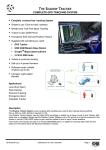
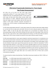
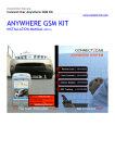
THE SHADOW COMPLETE GPS TRACKING SYSTEM • Complete ‘contract free’ tracking System • Simple to use “Click-to-track” software • Breadcrumb Trail/Time-lapse Tracking • Tracker is also GSM Phone • User Adjustable Geo-Fence • Emergency SOS Call and Position Feature • Supplied with everything you need: GPS Tracker USB GSM Modem Base Station GoogleTM Maps based Tracking software 2 SIM Cards • Vehicle and personal tracking • Dials upto 4 preset Numbers • Supports Multiple Trackers • Compact, Light weight discrete Applications Lone Work Alarm Fleet tracking Personal Tracking Emergency Alarm Valuables Tracker Description The Shadow Tracking System comes complete with everything you need to start tracking almost anything from a JCB to a child!. All that is required is a PC. The Shadow Tracking System uses the latest GPS technology to enable you to keep a track of your Vehicle, staff, loved ones or valuables. Simply load the Shadow Tracker Software onto a PC and set it to log the movement of the tracker or use the ‘FIND’ button to get a real time update of one or many Tracker locations. The Tracker unit may also be used as a normal GSM Mobile phone. In addition to receiving calls, there are four buttons on the tracker which will dial a preset telephone number, User Manual DS-SHADOW-0d ©2008 REG No 277 4001, ENGLAND. Page 1 THE SHADOW COMPLETE GPS TRACKING SYSTEM 1. Definitions....................................................................................3 2. In the Box .....................................................................................3 3. SIM Cards.....................................................................................4 4. USB GSM Modem Base Station .................................................4 5. Shadow Tracker...........................................................................5 6. Cable Accessories ......................................................................6 7. Hardware Installation ..................................................................7 8. Tracking System : Configuration ...............................................9 9. Tracking System: Operation.....................................................11 10. Troubleshooting Guide .............................................................13 11. Technical Specification ............................................................13 DS-SHADOW-0d ©2008 REG No 277 4001, ENGLAND. Page 2 THE SHADOW COMPLETE GPS TRACKING SYSTEM 1. Definitions The following definitions are used throughout this document and generally in connection with the control unit. GPS Global Positioning System – Used to locate the position of the tracker GPRS General Packet Radio Service – GSM Data connections. GSM Global System for Mobile communications Alphanumeric Characters in the range A to Z (upper and lower case), numbers in the range 0 – 9. Mobile GSM telephone with text message ability PC Personal computer which operates to the minimum requirements 2. In the Box Provided as part of the Shadow System: PART No Description Compact GPS Tracker unit / GSM Mobile Phone SHADOW-TRACKER USB Connecting Cable GSM-USBG10 USB GSM Modem Base Station (connects to user PC) CD-SHADOW CD Rom containing Shadow Tracker Software 2 x SIM-CARD Two Vodafone Pay-as-you-go SIM Cards. Tracker Mains Charger DS-SHADOW-0d ©2008 REG No 277 4001, ENGLAND. Page 3 THE SHADOW COMPLETE GPS TRACKING SYSTEM 3. SIM Cards Two Vodafone Pay-as-you-go SIM Cards are bundled with this system. The Shadow system can use either these or other SIM Cards / service providers with the following provisos; Notes 1. Only 3 Volt SIM cards will be correctly read and older 5 Volt types will be ignored. 2. Some types of pay-as-you-go SIM cards may require regular call activity (once every six months) to remain registered. 3. SIM cards that have been protected by means of a PIN (in a mobile phone) will not operate in the unit. 4. Because the Shadow system works by sending text messages, it is important that you consider the costs involved with using the system, these will be dependant on the network provider you choose. 5. For heavy use it might be advisable to obtain use a contact for free to text deal from a Service Provider. 6. Incoming voice calls to the SIM card should be barred before it is used in the Shadow Tracking System to avoid any possible errors. This can be achieved by calling the service provider. 7. The message memory of the SIM card should be clear before it is fitted to the GSM Shadow System. 4. USB GSM Modem Base Station The USB GSM Modem Base Station connects to the Base Station computer and communicates with the Shadow Trackers via Text messaging. Do not plug the modem into the PC prior to installing software! The GM Modem Base Station is a Plug and play device which is powered directly by the USB port and therefore requires little set-up. Simply install the drivers for the product, insert a SIM card and plug into a free USB port. More details can be found at http://www.rfsolutions.co.uk/acatalog/GSM_Modems.html Tip: This modem is not tied to the Shadow Tracking System and may also be used as a standard GSM/GPRS modem if required. DS-SHADOW-0d ©2008 REG No 277 4001, ENGLAND. Page 4 THE SHADOW COMPLETE GPS TRACKING SYSTEM 5. Shadow Tracker The Shadow Tracker is a small and powerful GPS/GSM/GPRS tracking device design and developed for remote positioning and lone worker applications. Do not plug the Shadow tracker into the PC before installing software. Fig 5.1 1. Install a SIM card a. Unlock the rear of the case and remove b. Remove the battery by lifting at the base c. Insert the SIM card ensuring the orientation is as per the diagram marked on the unit. 2. Charge the Shadow Tracker a. With the battery installed and the Shadow Tracker fully assembled b. Open the protective cover on the top of the unit (see Fig 5.1) c. Plug in the mini USB cable provided d. Connect the other end to the PC e. The LED on the front face will flash red while the Shadow tracker charges f. The LED will turn green when the battery is full. 3. Power On/Off the tracker a. Power on: Press and hold the power button fore 3secs (shown on Fig 5.1) the Shadow Tracker will flash it’s LED multiple colours and the power on tune will be heard. b. Power Off: Press and hold the power button (shown on Fig 5.1) the Shadow Tracker will flash it’s LED and the power off tune will be heard. c. When the Tracker is powered on the buttons will illuminate when pressed, when powered off this will not happen. DS-SHADOW-0d ©2008 REG No 277 4001, ENGLAND. Page 5 THE SHADOW COMPLETE GPS TRACKING SYSTEM 4. Phone Dialling / Answering / Hanging up a. Four Pre-set numbers can be dialled using the Shadow Tracker. b. To dial a number: i. Bring the tracker out of sleep mode by pressing the power button briefly ii. Press the OK button once briefly (Shadow Tracker will beep) iii. Press the button number you wish to dial iv. Press OK to start the call. NOTE: Numbers are set using the Shadow Tracker Software c. To answer an incoming call, press the OK button once. d. To end a call, press the power button briefly once. 5. Emergency Call / Transmit Location a. Pressing both Red SOS buttons (on each side of the Shadow Tracker) will cause the following to occur: i. Shadow Tracker will consecutively call each of the four preset telephone numbers ii. Shadow Tracker will SMS transmit its location to all four of the preset telephone numbers (using the shadow tracker software will plot the trackers position on Google Map even if a voice call is in progress) 6. Cable Accessories Bundled with the system is Mains Charger for the Shadow Tracker UB Lead to connect Shadow Tracker to PC DS-SHADOW-0d ©2008 REG No 277 4001, ENGLAND. Page 6 THE SHADOW COMPLETE GPS TRACKING SYSTEM 7. Hardware Installation Minimum Hardware Requirements: • Windows XP or Vista • CD-ROM Drive • 1 x Free USB Port (2 preferable) • Internet access • Internet explorer 7 or later. Before you can use the Shadow Tracker system you must install all three parts of the system onto the Base Station PC. These consist; 1. Install the Software onto the Base Station PC 2. Install the GSM Modem Base Station 3. Install the Shadow Tracker. Do not plug the GSM modem Base Station or the Shadow Tracker into the PC prior to installing software. 1. Install the Shadow software and Driver bundle from the CD provided a. Place the Shadow Tracker CD-ROM in the CD drive and wait for the auto run process to start. b. The software bundle will install along the drivers for all components of the Shadow system c. Follow the on screen instructions to install the software onto the PC d. Once Installation is complete (Fig 4.1) you may install the Modem and the Shadow Tracker Fig 4.1 DS-SHADOW-0d ©2008 REG No 277 4001, ENGLAND. Page 7 THE SHADOW COMPLETE GPS TRACKING SYSTEM 2. Install the GSM Modem Base Station a. Plug the GSM Modem Base Station into a free USB port on the PC b. Wait until the PC detects the modem c. When prompted, select the “Install the software automatically” option (Fig 4.2) Fig 4.2 d. Follow the on-screen instructions and complete the driver installation e. Three drivers are required, do not unplug the GSM Modem Base Station until all three have installed Windows indicates that installation for “Teltonika Modem USB G10” is completed f. Remove the GSM Modem Base Station from the PC. 3. Install the Shadow Tracker a. Plug the Shadow Tracker into the USB port using the Cable provided. b. Turn on the Shadow Tracker c. Select the “Install the software automatically” option d. Wait for the Shadow Tracker to be detected and follow the on screen instructions to Install the “6218 USB Modem Driver” e. After installation is complete (see Fig below) Unplug the Shadow Tracker from the PC. DS-SHADOW-0d ©2008 REG No 277 4001, ENGLAND. Page 8 THE SHADOW COMPLETE GPS TRACKING SYSTEM 8. Tracking System : Configuration To get started with your tracking system you need to ; Set the Preset Telephone numbers within each Shadow Tracker Setup each Shadow Tracker(s) name and telephone numbers on the GSM Base Station so that it can be tracked. 1. Open the Shadow Tracker System Software on the PC 2. Connect the Shadow Tracker a. Install a SIM card into the Shadow Tracker b. Connect the tracker to the PC using any free USB slot 3. Configure the Shadow Tracker’s numbers to dial Fig 7.3 a. From the Set-Up menu choose the Tracker Set-Up option (Fig 7.3) b. Plug the Shadow Tracker into the PC using the USB cable. c. Wait for the Software to detect the tracker, the connection status is shown at the bottom of the window. (Fig 7.3) d. Once Enter up to 4 numbers in the windows provided. e. Click the Set Numbers button to save the data f. Remove the Shadow tracker from the PC g. The Tracker will need to be restarted for the number changes to take effect. DS-SHADOW-0d ©2008 REG No 277 4001, ENGLAND. Page 9 THE SHADOW COMPLETE GPS TRACKING SYSTEM 4. Connect the GSM Modem a. Install a SIM card in the GSM Modem b. Plug the GSM Modem Base Station into any free USB slot on the PCB c. Wait for the Auto Detect process to complete and ensure that you have a good GSM signal using the Signal strength meter in the bottom right of the screen. (Fig 7.4) Fig 7.4 5. Set up a New User / New Shadow to be tracked a. From the Users menu select Create/Edit Users b. Click the Add Button and enter the details for the user c. Enter a name for the user and enter the phone number for the SIM card installed in the Shadow Tracker. Enter all numbers in International format (Fig 7.5) Fig 7.5 d. Choose whether or not to include the user in any Time-lapse updates (See Software details below) e. Close the Create/Edit Users window 6. Set-up is now complete and your Shadow Tracking system is ready to be used. a. Select your user from the Select User Box in the main window b. (the Select Date box will now show all data (if any) stored for this user, filtered by date. c. Use the Find User button to locate the Shadow tracker and show its position in the Map window. d. Full Software features explanation is given in section 9. DS-SHADOW-0d ©2008 REG No 277 4001, ENGLAND. Page 10 THE SHADOW COMPLETE GPS TRACKING SYSTEM 9. Tracking System: Operation Main Screen Select User The Select User drop down box shows a list of all known users, click on a user to show data stored for their movements Select Date The Select Date drop down box shows a list of all data stored on previous dates for the selected user. Delete The Delete button will delete all data shown in the window above. Find The Find User Button transmits an SMS to a selected User (Shadow tracker) and receives back its current location. When the Find User button is pressed the screen will refresh and show that users location with their name highlighted on the map. Plot Route The Plot Route button is used to plot the route taken by the selected User (Shadow tracker) over the time period selected this is then displayed in the browser window Find All The Find All button is used to find the current location of all users (Shadow Trackers) in the Users Menu. All users will be displayed in the map window and highlighted by name. File Menu Find, Find All, Plot Route – all as above Start Time Lapse The Start Time-Lapse option will start the time lapse monitoring service: See Time Lapse Set Up Users Create/Edit Users The Create/Edit Users menu allows you to add new users and remove those existing in the system. Choose also to include a user in Time Lapse Updates when in use (See Time Lapse Setup) Set-Up Modem Setup Allows the selection of a Com port and baud rate for modem communication. This should be set to auto detect using the tick box. Tracker Setup Tracker must be plugged into the PC for the below options to be useable. The Tracker Setup is split into 4 tabs: Phone Settings This allows the setting of the four telephone numbers to dial, these can be landline or mobile. Geo Fence DS-SHADOW-0d ©2008 REG No 277 4001, ENGLAND. Page 11 THE SHADOW COMPLETE GPS TRACKING SYSTEM The Shadow Tracker can be set to Geo-Fence itself inside a radius about a point. These settings must be entered manually, Latitude, longitude and the radius around this point to allow movement within are entered. If the Shadow Tracker goes outside this area an Alarm Message is sent to the preset numbers above. Comms Com Prot and baud rate settings for communication with the Shadow Tracker, these should be set to auto detect using the tick box. Tracker Live Shows current live data from the tracker Time Lapse Setup The Time lapse Setup Menu allows selection of a time period within which all users included in the Time Lapse Updates are constantly monitored (see at the Create/Edit Users section). Select the start and stop time for tracking ie within business hours or after school and choose the interval of each update. Display Setup Basic Setup Options for Plot Line colour and Map detail level are selectable. Google Earth If Google EarthTM is installed on the host PC, the Shadow Tracker can display the movements of a user/users instead of displaying using the inbuilt Google MapsTM Browser. About Minimise to Tray The Shadow Tracker can run in the background on the PC and minimise to the System tray if the option is ticked. About Shows the Modem Status, SIM card number, link to RF Solutions Ltd Home page and also give access to the Log for troubleshooting. DS-SHADOW-0d ©2008 REG No 277 4001, ENGLAND. Page 12 THE SHADOW COMPLETE GPS TRACKING SYSTEM 10. Troubleshooting Guide Shadow Tracker LED indication Indication Conditions Service Limited Service No Service Mode GSM + GPS not fixed GSM + GPS fixed GPRS + GPS GPRS + GPS fix mode Tracking + GPS not fixed Tracking + GPS fix Battery Battery Low Battery Charging Battery Full LED display Red Light Flashing Red Light On permanently Blue Light Flashing Turquoise Light Flashing Orange Light Brief Flash Green Light Brief Flash Orange Light Brief Flash Green Light Brief Flash Green/Red Lights Flashing Red Light Flashing Green Light On permanently 11. Technical Specification (specification for GSM base Station can be found using the link in Section 4) Shadow Tracker GPS Item Description Specification Chipset General GSW3 Frequency C/A Code Channels Position Velocity Time Reacquaistion Hot Start Warm Start Cold Start Altitude Velocity Acceleration SiRF Star III technology L1,1575.42Mhz 1.023 MHz chip rate 20 10 meters, 2-D RMS 5 meters 2-D RMS, WAAS 0.1 meters/second Within 1us of GPS time 0.1 sec av. 1 sec Typical 35 sec Typical 42 sec Typical 1800m 515m/s 4g max Item Description Specification Air Interface GSM Tri Band Class 4 Class 1 900/1800/1900MHz 2W @ 900Mhz 1W @ 1800/1900MHz GPRS Mutlislot Coding Scheme Class 12 CS1 ~ CS4 Accuracy TTFF Open Sky and Stationary requirements Dynamic Conditions GSM Data interface GRPS DS-SHADOW-0d ©2008 REG No 277 4001, ENGLAND. Page 13 THE SHADOW COMPLETE GPS TRACKING SYSTEM Physical/Operation Specifications Item Description Specification Dimensions Length Width Height With Battery Without Battery Operating Storage Up to 95% non-condensing 88.5mm 40mm 19.95mm 72g 57g -10 to 50 C -20 to 60 C Item Description Specification Supply Voltage GSM Other Operating Mode Standby (trace on) Power Saving (trace off) Capacity Dimension Charging time Output Voltage 4.2V Weight Temperature Humidity Electrical Specifications Power Consumption Battery (li-ion) 270mA 130mA 76mA 750mAh 43 x 31.7 x 6.9 mm 3hr 4.2V For more information or general enquiries, please call; R F Solutions Ltd., Unit 21, Cliffe Industrial Estate, Lewes, E. Sussex. BN8 6JL. England. E-mail : [email protected] www.rfsolutions.co.uk Tel: +44 (0)1273 898 000 Fax: +44 (0)1273 480 661 RF Solutions is a member of the Low Power Radio Association. Information contained in this document is believed to be accurate , however no representation or warranty is given and no liability is assumed by R.F. Solutions Ltd. with respect to the accuracy of such information. Use of R.F.Solutions as critical components in life support systems is not authorised except with express written approval from R.F.Solutions Ltd. DS-SHADOW-0d ©2008 REG No 277 4001, ENGLAND. Page 14