1
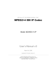
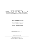
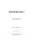
QVidium® TECHNOLOGIES, INC.
QVARQ Proxy Server™
QVAVQ Series
QoS Multimedia Proxy Servers
User’s Manual v.4
September 22, 2010
Application Firmware Version 47
© 2010 QVidium® Technologies, Inc.
12989 Chaparral Ridge Road, San Diego, CA 92130
Phone 858.792.6407 • Fax 858.792.9131
QVidium® QVARQ QoS Proxy Server™
User’s Manual v.4
Table of Contents
1
2
3
4
5
Introduction.............................................................................................................3
1.1
Overview ...........................................................................................................3
1.2
Network Setup..................................................................................................4
1.3
Ping....................................................................................................................5
1.4
Passwords and Security .................................................................................7
1.5
Upgrading .........................................................................................................7
1.6
System View.....................................................................................................8
Transmit Proxy.....................................................................................................10
2.1
Transmit Proxy Overview .............................................................................10
2.2
Transmit Proxy Configuration ......................................................................10
Receive Proxy ......................................................................................................12
3.1
Receive Proxy Overview ..............................................................................12
3.2
Receive Proxy Network Configuration........................................................12
3.3
ARQ Packet Transport & Error Correction.................................................14
3.4
Server Mode...................................................................................................17
Troubleshooting & Support ..............................................................................18
4.1
Troubleshooting – Common Problems .......................................................18
4.2
Support............................................................................................................18
Appendices ...........................................................................................................20
5.1
Appendix A: Transmit Proxy Configuration Parameters ..........................20
5.2
Appendix B: Receive Proxy Configuration Parameters ...........................21
5.3
Appendix E: Technical Specifications.........................................................23
5.4
Appendix F: Product Warranty Terms and Conditions.............................24
2 of 24 - Copyright 2010 QVidium® Technologies, Inc.
QVidium® QVARQ QoS Proxy Server™
User’s Manual v.4
1
Introduction
Congratulations on purchasing the QVidium® QVARQ Series QoS Multimedia Proxy Server™.
QVidium® QVARQ QoS Multimedia Proxy Server™ – Front View
1.1 Overview
The QVARQ QoS Multimedia Proxy Server™ creates up to 50 copies of an incoming multimedia
stream and redistributes it to up to multiple destinations across the Internet or any computer
network with sufficient bandwidth. Since the Internet does not support multicast, and because of
packet loss on Internet connections, the QVARQ QoS Proxy Server can be an invaluable part of a
real-time multimedia distribution system.
The multimedia stream can be any continuous stream of UDP or RTP IP packets. Generally, these
multimedia streams would contain video and audio data multiplexed as an MPEG2 Transport
Stream. The QVARQ adds QVidium’s patented Quality of Service (QoS) technologies, including
ARQ error correction and clock synchronization, to correct missing packets, data re-ordering, and
intermittent delays, in incoming multimedia streams. In addition, it also adds ARQ error correction
to each of the replicated outgoing medial streams. Unlike conventional media servers which add
tens of seconds or delay to the media streams they distribute in order to handle network loss and
impairments, QVidium’s QVARQ can handle live real-time media streams while only adding a
minimal amount of delay. QVidium QoS technology automatically measures the round-trip time of
each network connection from each destination to the QoS Server in order to help minimize the
total delay, while preserving the integrity of the multimedia stream. This allows real-time,
interactive access to multimedia content across the Internet.
With these advanced Quality of Service (QoS) features, the QVARQ QoS Multimedia Proxy
Server™ can redistribute a video stream from nearly any location in the world to dozens of
locations across the world over nearly any type of IP network, including wireless connections and
the public Internet, with unsurpassed video transport quality.
The QVidium QoS Proxy Server consists of a transmit proxy module and a receive proxy module
that operate simultaneously and in tandem to receive and redistribute a media stream from an IP
video source, such as a QVidium encoder. The receive module applies ARQ error correction and
the other QVidium QoS technologies to recondition a stream that may have been transported over
the Internet or other network with impairments. It then forwards the QoS-corrected IP stream to the
transmit module. If the IP video source is connected over a lossless network, then the receive
3 of 24 - Copyright 2010 QVidium® Technologies, Inc.
QVidium® QVARQ QoS Proxy Server™
User’s Manual v.4
proxy may not be necessary. In that case, the transmit module would receive an IP media stream
directly from the media source. The transmit module is responsible for replicating and applying the
ARQ error correction to each outgoing stream.
1.2 Network Setup
The QVARQ QoS Multimedia Proxy Server™ comes with a factory preset IP address of
192.168.1.31 and Netmask of 255.255.255.0. If you need to change this address, you could
temporarily set the IP address on your PC to any valid IP address starting with 192.168.1.XXX,
where XXX is any number from 1 through 254, except 31. Then connect your PC and the QVARQ
together through either an Ethernet switch with regular Ethernet cables, or you can bypass the
Ethernet switch and simply connect the PC to the QVARQ Server directly via a crossover Ethernet
cable.
Once connected, you can use any standard web browser to log into the appropriate LAN
configuration page under the Network menu and change the IP settings to permanent values
suitable for your network.
If you cannot change the IP address of your PC to connect into the QVARQ server, you can
connect a standard VGA monitor and keyboard to see its currently configured IP address. The
Ethernet address will appear in the message that it outputs during boot-up.
You can temporarily change the IP address to any address of your choice by typing the following at
the boot prompt: “ifconfig eth0 <IP Address> up”, where <IP Address> is a valid IPv4 address on
your local area network. For example, typing “ifconfig eth0 10.1.1.25 up” will change the IP
address temporarily to 10.1.1.25.
After changing the address, you can then easily connect to a standard web browser on a PC to
permanently reset the IP address to a convenient unused address on your network.
Once you have the PC and the QVARQ QoS Multimedia Proxy Server™ connected together on
the same network with the same subnet addresses, you can reconfigure the IP settings to new
permanent values through a standard web browser, such as Internet Explorer, Firefox, or Safari.
Follow the steps below to reconfigure the network settings through a web browser:
1) Point your web browser to http://192.168.1.31 (or the address you may have changed it to)
NOTE: The QVARQ QoS Multimedia Proxy Server™ requires user authentication to enter the web
browser or to log in using Telnet. The factory preset username is “root” and the password is also
“root.” Please enter these settings when prompted to access the system.
2) Click on “LAN 1” under the “Network” menu on the left. (This assumes that your QVARQ only
has one Ethernet port or you have configured and are connecting through the LAN 1 port. If you
have 2 LAN ports, you can use the LAN 2 page to set the network parameters of the second port.
However, you must use a different subnet for the second port.)
You should see a web page similar to the following network configuration web page:
4 of 24 - Copyright 2010 QVidium® Technologies, Inc.
QVidium® QVARQ QoS Proxy Server™
User’s Manual v.4
3) Change settings as desired and click “Apply”.
4) If you change the IP address, you will need to change the URL in the web browser to point to
the new address after clicking on “Apply”.
The Network LAN 1 panel (and LAN 2 panel on models with a second Ethernet port) allows you to
modify the static IP address parameters and DNS server settings, or to have these settings
automatically configured through DHCP. A Hostname panel allows you to specify the host name
for use in conjunction with a DNS server to assign a predetermined IP address.
Note on Resetting IP Address: In case you change the IP address or select DHCP and cannot
determine the IP address, you can connect a VGA monitor and keyboard and use the procedure
described above to see the current IP address and temporarily change it.
1.3 Ping
Selecting Ping allows you to test network connectivity by sending ping packets to an address or
hostname you specify. However, to use a hostname in place of an IP address, you must have
configured at least one DNS server.
5 of 24 - Copyright 2010 QVidium® Technologies, Inc.
User’s Manual v.4
QVidium® QVARQ QoS Proxy Server™
6 of 24 - Copyright 2010 QVidium® Technologies, Inc.
QVidium® QVARQ QoS Proxy Server™
User’s Manual v.4
1.4 Passwords and Security
The QVidium QVARQ QoS Multimedia Proxy Server™ requires a username and password to
protect access to its configuration settings. This includes both Web access and SSH access. The
default user name is “root” and the default password is also initially set to “root.” You can change
the password by selecting the Password menu item under the System Menu at the upper left of the
Web page.
Resetting Password: If you lose the password and need to reset it, follow the following steps:
1) Point your web browser to http://qvidium.com/reset
2) Under the “QVARQ Proxy Reset Scripts” heading, click on the “Reset Password” link.
3) Save the file as autorun to an USB thumb drive.
4) Insert the USB thumb drive into an USB connector on the back of the system.
5) After about 10 seconds, the system resets the password to “root”.
1.5 Upgrading
QVidium provides firmware upgrades from time to time to add new features, overcome limitations,
or to fix bugs. QVidium would provide any upgrades as a .pkg file that you can upload into the
QVARQ QoS Proxy Server via the web browser interface. To perform an upgrade, just follow the
following steps:
1) Copy the upgrade .pkg file into a convenient location on your PC.
2) Point your web browser to the server and click on “Upgrade” in the “System” menu.
3) Click on the “Browse” button and locate the upgrade file.
4) Click on “Upgrade” and wait for the upgrade to finish. DO NOT DISCONNECT FROM
POWER OR INTERRUPT THIS OPERATION UNTIL IT COMPLETES.
5) Click on “Reboot” from the system menu to reboot the server.
7 of 24 - Copyright 2010 QVidium® Technologies, Inc.
QVidium® QVARQ QoS Proxy Server™
User’s Manual v.4
1.6 System View
Rear View – Computer Interface ports and Power
Ref
Indicator
Description
1
Keyboard
PS/2 keyboard connector (purple). (Mouse not used.)
2
VGA Monitor
Standard VGA monitor connector.
Ref
Port
Description
3
LAN
Gigabit Ethernet (10/100/1000 Base-T) network port.
4
DC POWER
Regulated DC power input (12 VDC, 5 A).
8 of 24 - Copyright 2010 QVidium® Technologies, Inc.
QVidium® QVARQ QoS Proxy Server™
User’s Manual v.4
Inside Front View – USB Flash Memory and Fan
1
1 2
Ref
3
Component
4
12
Description
1 Power ON
Power on button.
2 Reset
Reset button.
3 USB Boot Flash
USB flash memory stick containing boot code.
6 Fan
Cooling fan.
Note: Serial number (not shown) is located on bottom of chassis.
Important Safety Information:
•
CAUTION: The QVARQ Proxy Server contains an internal 3V. Lithium battery.
RISK OF EXPLOSION IF BATTERY IS REPLACED BY AN INCORRECT TYPE. USE
ONLY PANASONIC CR2032 20MM COIN-TYPE BATTERY OR EQUIVALENT.
DISPOSE OF USED BATTERIES ACCORDING TO THE INSTRUCTIONS.
9 of 24 - Copyright 2010 QVidium® Technologies, Inc.
QVidium® QVARQ QoS Proxy Server™
User’s Manual v.4
2
Transmit Proxy
The QVidium QVARQ QoS Proxy Server consists of 4 transmit proxy modules and 4 receive
proxy modules. Each of these modules are independent of each other can be operated in any
combination.
Should your application require more than the available number of modules, please contact
QVidium Technologies, Inc. We also offer an unlimited version of the proxy server, without a web
interface, that may be more appropriate for your application. The unlimited version is configured
through a Linux shell script.
2.1 Transmit Proxy Overview
The transmit module of the QVidium QVARQ QoS Proxy Server is configured and operated from the
web browser. This section explains how to configure the server’s transmit parameters. The
configuration involves setting a few basic network parameters. There are no specific parameters
involving error correction or the other QoS technologies, since they are all automatically applied to
the outgoing stream.
From the web interface, you can configure any or all of the four transmit modules in the QVARQ
QoS Proxy Server. Each module, when registered with its own license key, operates and is
configured as an independent unit, and can process a separate media stream. If you need more
than four different simultaneous programs, then please contact QVidium Technologies for
information of the unlimited version of this technology.
2.2 Transmit Proxy Configuration
1. Enter http://IPAddress where IPAddress is the IP address of the QVidium QVARQ
QoS Multimedia Proxy Server™. (The default address is http://192.168.1.31.)
2. Click on “Profile” under one of the 4 “TX Proxy” items from the menu on the left. The “TX
Proxy Profile” interface should display in the main area to the right of the menu system,
as shown in Figure 1. NOTE: You can only configure a TX Proxy module that has been
registered with a valid license. If uncertain about the license state, please click on
“Register”. To obtain a license key that you have purchased, please e-mail QVidium at
[email protected] with the 32-digit license code. Without this code we cannot issue you a
license key.
3. On the transmit profile configuration page, enter the source UDP port to match the UDP port
of the incoming IP media stream. If the source media stream does not have RTP
encapsulation, but instead encapsulates the MPEG2 Transport Stream as the raw payload of
UDP packets, check “Source UDP Only”. If the incoming stream does not have ARQ and
is a multicast stream, then additionally, you must enter the multicast IP address. If you are
receiving a unicast IP stream that was directly only to this server, please leave the multicast
address field blank.
4. You will also have to choose a destination IP address and UDP port number, for the
replicated output streams. The ARQ port and the destination UDP media port should be
different values.
10 of 24 - Copyright 2010 QVidium® Technologies, Inc.
QVidium® QVARQ QoS Proxy Server™
User’s Manual v.4
5. After entering all the parameters as described in steps 3 and 4, and shown in Figure 1 below,
press the “Save” button to save your changes. None of your changes will be saved nor have
any effect unless you first save them. If you have any doubt about the parameters selected
when running the encoder, you should click on Profile after saving the parameters or starting
the proxy server to see the current operational settings.
6. Optionally, you can export any saved parameters to a file or import parameters using the
Export and Import menu items.
7. Lastly, click “Start” to start the proxy server.
Figure 1: Transmit (Tx) Proxy Configuration.
11 of 24 - Copyright 2010 QVidium® Technologies, Inc.
QVidium® QVARQ QoS Proxy Server™
User’s Manual v.4
3
Receive Proxy
3.1 Receive Proxy Overview
The receive modules of the QVidium QVARQ QoS Proxy Server are configured similarly to the
transmit modules. This section explains how to use the Web pages to configure the server’s receive
parameters. The receive modules of the QVidium QVARQ QoS Proxy Server are configured from
three profile web pages: Network Configuration, ARQ Configuration, and Server Configuration, as
described below and shown in Figures 2 through 4.
From the web interface, you can configure any or all of the four receive modules in the QVARQ QoS
Proxy Server. Each module, when registered with its own license key, operates and is configured as
an independent unit, and can process a separate media stream. If you need to receive more than
four different simultaneous programs, then please contact QVidium Technologies for information of
the unlimited version of this technology.
3.2 Receive Proxy Network Configuration
Figure 2 shows the receive proxy network configuration page. To configure the IP network
parameters, within the Network Parameters section of the proxy profile, select among ARQ, RTP,
or UDP packet transport. Also, specify the destination IP address and UDP port number. The
destination IP address may be a multicast or a unicast IP address. The proxy receives the video
and audio IP streams as UDP packets in all cases, regardless of the type of packet transport you
select. Specifying UDP eliminates the RTP header and encapsulates the encoder’s multiplexed
MPEG-2 transport stream directly as the payload of the UDP packet. Selecting ARQ and RTP add
an RTP header to the UDP packet stream. The RTP header adds a timestamp and packet
sequence number before inserting the MPEG-2 transport stream packets into the RTP/UDP/IP
packet payload.
The network interface to the receive proxy includes QVidium’s patented synchronized network jitter
buffering mechanism to help remove the effects of variable network delays. In the receive proxy
network interface, you may specify a delay for this jitter buffer in milliseconds. When using ARQ
network transport mode, a jitter buffer holds the specified number of milliseconds of packets to give
the decoder ample time to account for random delays and to allow the decoder to correct packet
ordering. The receive proxy uses RTP sequence numbers of incoming packets to insert incoming
packets into their proper place in the de-jitter buffer before releasing those packets into the receive
proxy. The jitter buffer also uses the RTP timestamp to synchronize the receive proxy’s network
clock with the video source to adjust the jitter buffer hold time.
In addition to the jitter buffer, the receive proxy includes an out-of-order buffer that, like the jitter
buffer, will help restore packet order. However, in contrast to the jitter butter, the out-of-order buffer
is a simple reordering shift register that must first fill to the specified size before it will start
outputting packets. You can specify the size of this jitter and out-of-order buffer in the network
configuration.
The following procedure will help you configure the network portion of the receive proxy:
1. Enter http://IPAddress where IPAddress is the IP address of the QVidium QVARQ
QoS Multimedia Proxy Server™. (The default address is http://192.168.1.31.)
2. Click on “Profile” under one of the four “RX Proxy” items from the menu on the left. The
“RX Proxy Profile” interface should display in the main area to the right of the menu
system, as shown in Figure 2. NOTE: You can only configure a RX Proxy module that has
12 of 24 - Copyright 2010 QVidium® Technologies, Inc.
User’s Manual v.4
QVidium® QVARQ QoS Proxy Server™
been registered with a valid license. If uncertain about the license state, please click on
“Register”. To obtain a license key that you have purchased, please e-mail QVidium at
[email protected] with the 32-digit license code. Without this code we cannot issue you a
license key.
3. On the receive profile Network configuration page, IP Transport, Source UDP Port, Jitter, and
Out-of-Order Size relate to the incoming IP media stream. Select the IP transport to match the
incoming IP source media stream. You can select ARQ only if the source stream is being
unicast from a device that incorporates QVidium’s ARQ error correction. Otherwise, enter
UDP or RTP as appropriate. UDP is the most common IP video transport and therefore has
the widest compatibility. However, using RTP will allow you to measure any packet loss on
the status page.
4. As with the TX proxy, enter the source UDP port to match the UDP port of the incoming IP
media stream. If the source media stream does not have RTP encapsulation, but instead
encapsulates the MPEG2 Transport Stream as the raw payload of UDP packets, check
“Source UDP Only”. If the incoming stream does not have ARQ and is a multicast stream,
then additionally you must enter the multicast IP address. If you are receiving a unicast IP
stream that was directly only to this server, then please leave the multicast address field
blank.
5. You will also have to choose a destination IP address and UDP port number, for the
replicated output streams. The ARQ port and the destination UDP media port should be
different values, as shown in Figure 2.
Figure 2: Rx Proxy Network Configuration.
13 of 24 - Copyright 2010 QVidium® Technologies, Inc.
QVidium® QVARQ QoS Proxy Server™
User’s Manual v.4
3.3 ARQ Packet Transport & Error Correction
The QVidium QVARQ QoS Multimedia Proxy Server™ features some of the most powerful and
advanced error correction capabilities found in any video over IP product. The QVidium QVARQ
QoS Multimedia Proxy Server™ implements QVidium’s patented ARQ error correction and clock
synchronization (US Patents #7,551,647 and #7,522,528) for the more robust video transmission
with the lowest delay. QVidium’s ARQ (Automatic Retransmission Request) is a dynamically
adjusting feedback error correction mechanism designed specifically to enable the highest quality
video transport over wireless networks and the Internet. ARQ senses packet loss at the receiver
and requests replacement packets from the server. ARQ can provide nearly flawless reproduction
of a video stream even through extremely lossy or congested networks.
In contrast with FEC, QVidium’s ARQ is a feedback mechanism that detects packet loss at the
receiver and requests the retransmission of only those lost packets from a video source. A userconfigurable buffer at the receiver (decoder) delays the video stream just long enough to allow the
system to replace any missing packets and re-insert them in their proper order without disturbing
play out of the video stream. Because ARQ senses actual packet loss, rather than attempt to
predict packet loss, it can precisely and completely restore all lost packets without disturbing timing
of the video play out. In contrast to FEC, ARQ can successfully recover lost packets regardless of
the magnitude or pattern of the packet losses, provided that the network connection has enough
capacity to send both the original video stream and the replacement packets.
ARQ shares similarities with robust packet transport protocols, such as TCP/IP in that both use
feedback to create robust network packet transport. However TCP/IP uses a sliding window that
limits the number of packets that a source can have in transit and requires a positive
acknowledgement for each window of packets. This limits TCP’s throughput, especially over links
with long latencies. Furthermore, under heavy loss conditions, TCP/IP scales back the data
transmission rates and provides no concise deadlines or constraints on packet delivery times. For
real-time video, this limits the usefulness of TCP/IP and makes it unacceptable for live, low-latency
video transport.
In contrast with TCP/IP, QVidium designed its patented ARQ error correction specifically for live,
interactive, real-time video and audio signals to automatically recover nearly all lost packets with
minimal latency and over nearly any link loss conditions. It adds a small configurable amount of
delay to the network transport in exchange for significantly improving the robustness and reliability
of video transport.
This section explains how to configure the video transport capabilities of the QVidium QVARQ QoS
Multimedia Proxy Server™ and how to enable ARQ error correction.
3.3.1 ARQ Operation
Automatic Retransmission Request (ARQ) tries to recover any packets lost during transport to the
decoder by adding a small amount of delay at the decoder during which time the decoder would
have time to detect and request any missing packets. The size of this delay should also include
adequate time for the missing packet to be received and inserted into the play out queue so that
the video stream can continue to flow smoothly and unimpeded to the MPEG decoder.
To enable ARQ, you must first select ARQ transport from the Profile dialog. ARQ transport
must also be enabled at this receive proxy. With ARQ selected and the encoder started, the
encoder will begin to save outgoing packets for later retransmission, when necessary. You must
also be certain to configure any firewalls to allow the ARQ retransmission request packets through.
The default port for these upstream ARQ request packets is UDP port 7020, although you can
configure this to any other valid, non-conflicting UDP port. However, if you choose to change the
14 of 24 - Copyright 2010 QVidium® Technologies, Inc.
User’s Manual v.4
QVidium® QVARQ QoS Proxy Server™
ARQ request port, you must make certain the settings at the encoder and decoder match.
At the receive proxy, the ARQ error correction mechanism first buffers incoming packets in a
synchronized network de-jitter buffer that maintains a constant, configurable delay for incoming
packets. The de-jitter buffer processes RTP sequence numbers and reorders packets as
necessary to restore proper packet sequence and to buffer against erratic network delays. Its goal
is to output a smooth, consistent flow of packets with increasing sequence numbers. This output
feeds the ARQ error correction mechanism.
The ARQ unit at the receive proxy watches for gaps in RTP sequence number from the de-jitter
buffer output, and immediately sends out retransmission requests when necessary. Incoming
retransmitted ARQ packets bypass the de-jitter queue and find their correct place in the ARQ
buffer, so that by the time packet are output by the ARQ buffer, the ARQ error correction
mechanism should no longer contain any missing packets.
When the encoder and decoder are both started, the receive proxy automatically measures the
round-trip delay and packet jitter to the encoder and automatically configures ARQ for optimal
operation according to a few basic user-specified parameters, as described in Section Error!
Reference source not found..
Note: For ARQ error correction to be enabled, you must select ARQ transport at both the encoder
or video source and this receiver proxy. The encoder/video source must be configured to allow
upstream ARQ request packets to the source. If you set the ARQ port equal to the UDP port, then
for most firewalls QVidium’s ARQ will automatically configure the firewall to allow in the upstream
ARQ requests.
Figure 3: Rx Proxy ARQ Error Correction Configuration.
15 of 24 - Copyright 2010 QVidium® Technologies, Inc.
QVidium® QVARQ QoS Proxy Server™
User’s Manual v.4
3.3.2 ARQ Error Correction Configuration
The configuration page for ARQ is shown above in Figure 3. To enable ARQ, you must first select
ARQ transport from the Profile dialog. Also, ARQ transport must be enabled at the encoder.
With ARQ selected and the decoder started, the decoder will watch for gaps in the RTP sequence
numbers from the output of the jitter buffer. When it detects missing packets, it sends
retransmission requests to the encoder so that the encoder can quickly resend any missing
packets. Incoming retransmitted ARQ packets bypass the network de-jitter queue and find their
correct place in the ARQ buffer, so that by the time packet are output by the ARQ buffer, the output
of the ARQ buffer should no longer contain any missing packets.
The ARQ has five parameters that can be configured in manual mode: Target Latency, Burst
Drop, Robust Mode, Number Retries, and Round Trip Time. In automatic mode, the
system automatically measures and calculates the Round Trip Time and Number Retries. In
most cases automatic mode using the default parameters should be adequate.
Of the required parameters, the first parameter, Target Latency, specifies the total delay, in
milliseconds, allotted for the request, retransmission, and recovery process. The ARQ mechanism
will attempt as many retries as possible within this target latency time. Thus, larger target latency
times increase the delay before video is output, but allows for more chances of requesting and
recovering any missing packets.
A Burst Drop delay can also be specified to delay any retransmission requests for a time equal
to the maximum expected packet loss time, such as from dynamic router changes of other sources
of burst loss.
A Robust Mode can also be selected. When selected (checked), a minimum of two tries will be
attempted for recovering any missing packets. When not selected (unchecked), ARQ will always
try at least once to recover any missing packets.
To help with firewall configuration and to handle potential port conflicts, the user can change the
default port that ARQ uses to send upstream retransmission requests, ARQ Port. However, you
must make certain that the same ARQ port number is set in both the encoder as in the decoder.
Although the automatic measurement of the round-trip time uses multiple measurements to take
into account random network delays, for some networks you might wish to specify a larger roundtrip value, or to specify a larger number of retries in case the upstream link loses some of the
retransmission request messages. In automatic robust-mode of ARQ operation, the system
automatically measures the round-trip time and divides that number into your specified Target
Latency to determine the number of retries to use. However in Manual Mode, you can force ARQ
to always use a specified number or retransmission requests.
NOTE: Remember to click Save after changing any parameters, or your changes will be lost. You
also have to click Start for any changes to take effect.
16 of 24 - Copyright 2010 QVidium® Technologies, Inc.
QVidium® QVARQ QoS Proxy Server™
User’s Manual v.4
3.4 Server Mode
In addition to passively listening for a stream that you would push from a media source, you can
also set the receiver proxy to be in Server Mode where it pulls a stream from a QVidium encoder
or even another QVidium TX Proxy Server. In Server mode, when you start the receive proxy it
remotely start a QVidium encoder and initiates a video stream. To put a QVAVC encoder in server
mode, simply leave the Destination IP Address blank and Start the encoder. This will cause the
encoder to listen for a start packet from the receive proxy.
To have the receive proxy initiate a stream in Server mode, go to the Server tab and configure the
following parameters, as shown in Figure 4, below.
1. Click ‘Yes’ under “User Server” so that Server mode will be enabled when you next start the
proxy receiver.
2. Enter the IP address or hostname of the media source you want to pull the stream from.
3. Set the Echo Port to match the echo port on the media source. Normally the echo port has a
default value of 7. You should keep this value at the default of 7 unless you have reason to
change it and you have also changed the corresponding entry on the video source.
4. Click Start on the receive server to restart it in Server mode.
Figure 4: Rx Proxy Server Mode Configuration.
17 of 24 - Copyright 2010 QVidium® Technologies, Inc.
QVidium® QVARQ QoS Proxy Server™
User’s Manual v.4
4
Troubleshooting & Support
The QVARQ QoS Multimedia Proxy Server™ includes a number of features to aid in system
security and logging.
4.1 Troubleshooting – Common Problems
No response from web browser or cannot ping system
1. Make certain that device is powered on and connected to your network.
2. Check that green LAN light in front is lit and link light at RJ-45 port is on.
3. Make certain that device is on the same subnet as the computer you plan to connect to.
(Either use a cross-over Ethernet cable to connect directly to the computer or connect
through the same switch as your computer.)
4. Connect a VGA monitor and keyboard to the proxy server and type “ifconfg –a” to see the IP
address and netmask.
5. Open a shell window (On Windows™ select “Start/Run…” and type “cmd”).
6. Clear the ARP cache by typing “arp –d” and hit Enter.
7. Try pinging the system by typing “ping <IP address from step 4>”, for example type
“ping 192.168.1.31”.
Cannot get TX Proxy to send IP packets
1. Check that a valid video signal is connected to the video Input you have configured. Use
the Encoder/Profile page to select among Composite and S-Video inputs. Make certain
that you Saved the profile and afterwards hit the Start menu item.
2. Make certain that device is powered on and connected to your network.
3. Check that green LAN light in front is lit and link light at RJ-45 port is on.
4. Make certain that you have entered the correct IP address for the destination (under
Encoder/Profile) and the correct gateway (under Network/Configure) if the receiver is on
another subnet.
5. Try pinging the destination system clicking on Network/Ping and entering the IP address for
the decoder device.
4.2 Support
For specific technical help, we kindly ask that you first contact the reseller or distributor from whom
you purchased your QVidium product. If you still require further assistance, or you purchased your
product directly from QVidium, please contact QVidium Technologies, Inc. by either phone or email at:
18 of 24 - Copyright 2010 QVidium® Technologies, Inc.
QVidium® QVARQ QoS Proxy Server™
User’s Manual v.4
Phone: (858) 792-6407
Phone Support Hours: Monday - Friday 9:00 am to 5:00 pm PST
E-mail: [email protected]
E-mail response time: within 24-hours
19 of 24 - Copyright 2010 QVidium® Technologies, Inc.
QVidium® QVARQ QoS Proxy Server™
User’s Manual v.4
5
Appendices
5.1 Appendix A: Transmit Proxy Configuration Parameters
Network Parameters
The fields below relate to Ethernet/IP video transport settings.
IP Transport: This selects the type of video IP packet encapsulation and error correction
used by the codec in generating a Video/IP stream. All packetized video transport
mechanisms encapsulate a multiplexed constant bit rate MPEG-2 transport stream.
•
ARQ uses QVidium’s patented error correction mechanism based on a timeconstrained selective packet retransmission algorithm. However it relies upon an
upstream channel on UDP port 7020.
•
RTP disables all error correction mechanisms, but still encapsulates the MPEG-2
multiplexed data according to RFC2733.
•
UDP is similar to the RTP transport above, but does not add the RTP header to the
UDP packets. Instead it simply encapsulates the MPEG-2 transport stream data
directly into the UDP/IP packet payload.
Destination IP Address or Hostname: This specifies the IP address or Hostname for the
Video/IP stream.
UDP Port: This specifies the UDP port number (P), base 10, for the Video/IP stream.
ARQ
The parameters below ONLY pertain to ARQ error correction. They will be ignored when
ARQ IP Transport is not selected.
ARQ Port: By default, ARQ normally sends upstream retransmission request packets on
UDP port 7020. You can change this ARQ Port setting to any valid and non-conflicting
UDP port. However, you must make certain that you specify the same port number at both
the encoder and the decoder. We suggest that you reset this to be the same port as the
media UDP port (usually 10000) to help with opening firewall problems.
20 of 24 - Copyright 2010 QVidium® Technologies, Inc.
QVidium® QVARQ QoS Proxy Server™
User’s Manual v.4
5.2 Appendix B: Receive Proxy Configuration Parameters
This section explains the parameters related to the setup and operation of the receive
proxy, the error correction algorithms, and network transport configuration.
Network Parameters
The fields below relate to Ethernet/IP video transport settings.
IP Transport: This selects the type of video IP packet decapsulation and error correction
expected by the codec in receiving a Video/IP stream.
•
ARQ uses QVidium’s patented error correction mechanism for lost packet
recovery. ARQ encapsulates the video stream as a standard MPEG-2 Transport
Stream as the payload of UDP packets with an RTP packet header as per
RFC2733. It relies upon an upstream channel on UDP port 7020.
•
RTP disables all error correction mechanisms, but still allows measuring packet
loss.
•
UDP is similar to the RTP transport above, but expects raw UDP packets without
an RTP header. It expects to receive the MPEG-2 transport stream directly from
the UDP payload. Use this setting for interoperability with some Set-Top Boxes.
Multicast Address: This specifies the IP multicast address, if any, to listen to for the
Video/IP stream. For receiving a unicast video/IP stream, leave this field blank.
UDP Port: This specifies which UDP port number (P), base 10, to listen on for the
Video/IP stream.
Jitter: Packets in incoming IP packet streams may lose their ordering or suffer variable
delays during transport through an IP network. The proxy receiver buffers all incoming
video/IP packets in a buffer and reorders RTP encapsulated packets by RTP sequence
number. This parameter specifies the size of this incoming packet buffer in milliseconds of
delay. Specify 0 here to disable this additional buffering when latency needs to be
minimize.
ARQ Parameters
The parameters below ONLY pertain to QVidium ARQ error correction. They will be
ignored unless ARQ is selected for IP Transport.
Target Latency: QVidium’s ARQ error correction operates through the addition of a
small additional buffering delay to provide enough time to request and receive
replacement for each lost packet. Target Latency gives the ARQ mechanism a target value
for determining the necessary ARQ delay. The ARQ divides the Target Latency, specified
in milliseconds, by the round-trip time to the video encoding source to determine the
number of request attempts. Unless Robust Mode is enabled, it sets a minimum ARQ
21 of 24 - Copyright 2010 QVidium® Technologies, Inc.
QVidium® QVARQ QoS Proxy Server™
User’s Manual v.4
latency of one round-trip time. A larger Target Latency allows the system to increase the
number or repeat requests.
Max Burst Drop: Burst packet losses are common occurrences in many IP networks and
the Internet. IP networks may dynamically change paths in response to load balancing,
link failure avoidance, and for other reasons. During a re-route, a sequence of queued
packets on a discontinued path may be dropped. A burst of packets may be dropped when
higher priority packets stall a lower priority buffer. ARQ will notice a burst packet loss
when the first packet after the loss arrives at the codec. Setting the Max Burst Drop Delay
(in milliseconds) will delay the ARQ repeat request by this amount to handle packet burst
losses.
Robust Mode: Normally, the ARQ will only require that a minimum of one repeat request
is sent to the video encoding source device, regardless of the Target Latency. However,
enabling Robust Mode will increase the minimum number of repeat requests to a minimum
of two retries.
ARQ Port: By default, ARQ normally sends upstream retransmission request packets on
UDP port 7020. You can change this ARQ Port setting to any valid and non-conflicting
UDP port. However, you must make certain that you specify the same port number at both
the encoder and the decoder. To help bypass firewall blocking, we suggest that you reset
this to be the same port as the media UDP port, usually 10000.
Server Parameters
The parameters below ONLY pertain to the operation of the QVidium QVARQ QoS
Multimedia Proxy Server™ with a QVidium QoS Proxy Server. Leave this disabled when
not connecting to a QoS Proxy Server.
This feature allows the decoder to initiate and receive a unicast stream from a QoS Proxy
Server. You must provide the IP address and control port for the QoS Proxy Server. The
decoder then sends a control packet upstream to the server when you start the decoder.
Use Server: Select No to disable this feature. Select Yes to enable operation with a QoS
Proxy Server.
IP Address or Hostname: Enter the IP address of the QoS Proxy Server to which the
decoder will send a start-stream message.
Echo Port: Normally, this should be left to the default UDP port 7. This port number must
match the value at the QoS Proxy Server. In addition, you may need to configure a firewall
at the server to allow ingress for packets on this port.
22 of 24 - Copyright 2010 QVidium® Technologies, Inc.
QVidium® QVARQ QoS Proxy Server™
User’s Manual v.4
5.3 Appendix E: Technical Specifications
Specifications
Network Interface:
•
1 IEEE 802.3 10/100/1000 Base-TX Ethernet (RJ-45)
IP Network Stream Conditioning & Error Correction (EC):
•
QVidium patented ARQ error correction
Network Protocols:
•
IP Encapsulation: RTP/UDP/IP and UDP/IP
•
IGMP v.3 Multicast
•
DHCP
Configuration and Monitoring:
•
Web setup & monitoring interface over IP network
•
SSH
Electrical:
•
DC Power Input: 12 VDC, 5 A, 60 Watts average
•
Auto sensing AC power adapter included
Mechanical:
•
Dimensions: 7.7”(W) x 8.75” (D) x 2.5” (H)
•
Dimensions (mm): 195 (W) x 222 (D) x 64 (H)
•
Unit Weight: 3.0 lbs (1.36 Kg)
Environmental:
•
Operating temperature: 0 to 50o C
•
Operating humidity: 0 to 90% R.H., non-condensing
•
Non-operating temperature: -20 to 70o C
•
Non-operating humidity: 0 to 95% R.H., non-condensing
Warranty:
•
Parts and labor: 1-year
23 of 24 - Copyright 2010 QVidium® Technologies, Inc.
User’s Manual v.4
QVidium® QVARQ QoS Proxy Server™
5.4 Appendix F: Product Warranty Terms and Conditions
1)
Warranty Statement
Thank you for purchasing a QVidium product. All QVidium products come with a one-year limited
warranty against defects in material and workmanship during the warranty period. If a product
proves to be defective in material or workmanship during the warranty period, QVidium will, at its
sole option, repair or replace the product with a similar product. Replacement Product or parts may
include remanufactured or refurbished parts or components. The replacement unit will be covered
by the balance of the time remaining on the customer's original limited warranty. QVidium provides
no warranty for the third-party software included with the product or installed by the customer.
QVidium does not warrant that the operation of any product will be interrupted or error free and
QVidium is not responsible for damage arising from failure to following instructions relating to the
product’s use.
2)
Warranty Conditions
The warranty is valid only for the first consumer purchaser and is not transferable. Proof of
purchase will be required for any limited warranty. The warranty does not cover: 1) any product on
which the serial number has been defaced, modified or removed or 2) Damage, deterioration or
malfunction resulting from: a) Accident, misuse, neglect, fire, water, lightning, or other acts of
nature, unauthorized product modification, or failure to follow instructions supplied with the product;
b) Repair or attempted repair by anyone not authorized by QVidium; c) Damage to or loss of any
programs, data or removable storage media; d) Software or data loss occurring during repair or
replacement; e) Any damage of the product due to shipment; f) Removal or installation of the
product; g) Causes external to the product, such as electric power fluctuations or failure; h) Use of
supplies or parts not meeting QVidium’s specifications; i) Normal wear and tear; j) Failure of owner
to perform periodic product maintenance; k) which has been subjected to unusual physical or
electrical stress, misuse, abuse, power shortage, or negligence or; l) Any other cause which does
not relate to a product defect.
3)
Warranty Procedure
For the duration of the warranty period, QVidium will replace or repair defective products. If a
product is suspected of being defective, the owner should contact the reseller or distributor that
sold the product. A representative will authorize the exchange or repair of the defective item.
Products must be shipped in the original or comparable packaging with shipping and insurance
charges prepaid in U.S. currency.
4)
Limitation of Warranty
Neither QVidium nor its third party suppliers make any other warranty or condition of any kind
whether expressed or implied, with respect to the QVidium products, and specifically disclaim the
implied warranties or conditions of merchantability, satisfactory quality, and fitness for a particular
purpose.
5)
Limitation of Liability
Except for the limited obligations specifically set forth in this warranty statement, in no event shall
QVidium or its third party suppliers be liable for direct, indirect, special, incidental, or consequential
damages, whether based on contract, tort, or any other legal theory and whether advised of the
possibilities of such damages.
Some states do not allow limitations on how long an implied warranty lasts or the exclusion or
limitation of incidental or consequential damages, so the above limitations and/or exclusions may
not apply to you. This warranty gives you specific legal rights and you may also have other rights
which vary from state to state.
24 of 24 - Copyright 2010 QVidium® Technologies, Inc.