1
TI-DM3730-EM User Manual
Directory
1.
TI-DM3730-EM in t r o d u c t io n ..................................................................................... 4
1.1. TI-DM3730-EM BRIEF INT RODUCT IO N ....... ................................................ 4
1.2. TI-DM3730-EM model... ............................................................................................ 5
2.
TI-DM3730-EM Ha r d wa r e in t r o d u c t ion.............................................................. 6
2.1
TI-DM3730-EM hard ware spe cif ica tion .......................................................... 6
2.1.1
Block diagram ..................................................................................... 6
2.1.2
TI-DM3730-EM hardware parameter .................................................... 6
2.1.3
TI-DM3730-EM working environment ................................................... 8
2.1.4
TI-DM3730-EM mechanical information................................................ 8
2.2
TI-DM3730-EM pin definit ion ............................................................... ……….9
2.2.1
Pin definition........................................................................................ 9
2.2.2
Key/ Switch specification ................................................................... 10
2.2.3
LED specification............................................................................... 10
2.1. Connec tor des crpt ion ................................................................................. 10
2.4
TI-DM3730-EM pin definit ion ................................................................... ….15
TI-DM3730-EM b a s ic f u n c t io n ....................................................................... 20
3.1. TI-DM3730-EM co mpu ter s yste m ................................................... ……. ... 20
Standard accessories............................................................................................. 20
3.
Optional accessories ....................................................................................... 20
3.2. TI-DM3730-EM conne ction co nfigur ation ............................................. …….21
3.2.1. External port connection.................................................................... 21
3.2.2
The sequence to power on the system .............................................. 22
3.2.3
The sequence to power off the system .............................................. 23
4. TI-DM3730-EM L in u x s y s t e m c o n f ig u r a t io n .................................................. 24
4.1. Sys te m boo ting method and pro cedure ..................................................... 24
4.1.1. The system boot process:............................................................... 24
5.
4.1.2. SD card boot process........................................................................ 25
4.1.3. Nandflash boot process..................................................................... 25
4.2. Disp lay sett ing ............................................................................................ 26
4.2.1
VGA port display:............................................................................... 26
4.2.2
4.3 inch touch screen display ............................................................ 27
4.2.3
7 inch touch screen display ............................................................... 27
4.3. DEMO soft ware de monstra tion .................................................................. 27
4.3.1
3D Demo ........................................................................................... 28
4.3.2
Quake3 ............................................................................................. 29
4.3.3
DVSDK.............................................................................................. 30
4.3.4
Video input demonstration ................................................................. 30
4.3.5
USB camera demonstration............................................................... 33
4.3.6
Play video demonstration .................................................................. 35
Co n s t r u c t Emb e d d e d L in u x s o f t wa r e d e v e lo p me n t e n v ir o n me n t ............... 36
2
6.
5.1
Linu x soft ware de velop ment en viron ment de scription .............................. 36
5.2
Build th e soft ware d eve lop ment envir on ment ............................................ 36
5.2.1
Install the VMare-workstation-6.5.0.................................................... 36
5.2.2
Ubuntu installation............................................................................. 40
5.2.3
Set the file share configuration for Virtual machine and the host. ....... 44
5.2.4
Build cross compiler .......................................................................... 46
5.3
Seria l ter mina l soft ware use ....................................................................... 47
5.4
Moun t the net work f ile sy ste m NFS ........................................................... 48
Bu ild t h e s o f t wa r e d e ve lo p me n t e n v iro n me n t ............................................... 50
6.1
Sys te m co mpile .......................................................................................... 50
6.2
6.1.1
6.1.2
First stage code x-loader compile ...................................................... 50
Second code u-boot compile ............................................................. 52
6.1.3
6.1.4
Kernel compile .................................................................................. 52
Make the file system image ............................................................... 53
Progra mming L inu x sys te m ima ge ............................................................. 54
6.2.1
6.2.2
6.3
6.2.3
NAND Flash system image update.................................................... 58
Linu x Ap plicat ion Develop ment .................................................................. 60
6.3.1
6.3.2
7.
Make SD card to boot........................................................................ 54
SD Card system image updates ........................................................ 57
Set boot auto-run programs............................................................... 60
Shield displays the login screen......................................................... 61
6.3.3
Download and install software ........................................................... 62
6.3.4
ALSA Sound settings......................................................................... 62
6.3.5
General Linux application development process................................ 63
6.4
De mo s yste m runnin g perfor mance ........................................................... 64
a p p e n d ix .............................................................................................................. 68
7.1
Sche ma tic and CPU boar d pin def init ion ................................................... 68
Chapter One
1. TI-DM3730-EM introduction
1.1. TI-DM3730-EM BRIEF INTRO DUCT ION
TI-DM3730-EM from PardazeshSabz is a Low-power, high-performance single board
computer
based on SOM35x. Designed with EPIC Standard and extendable architecture . TIDM3730-EM helps users leverage the benefits of OMAP35x processor comprising of
advanced Superscalar ARM Cortex-A8 RISC core with NEO N co-processing, IVA2.2
subsystem with a C64x+ digital signal processor (DSP) core and SGX subsystem for 2D
and 3D graphics acceleration (PowerVR).
The TI-DM3730-EM helps users building their products around the OMAP35x enjoy
the benefits of faster user interfaces, faster data access and multi -standard
encode/decode. Resolution up to 1280*720, Supports multiple display output, such as
VGA, LCD,
S-Video and AV composite video output. Supports multi-standard encode/decode at D4
(1280¡720p/60Hz ) 30 fps. Supports multiple embedded operation system, such as
Android, Embedded Linux, WinCE.
TI-DM3730-EM co mes with X-Loader、U-Boot、Linux Kernel(V2.6.32) and UBIFS
File system for Linux. The PSP Software Release from TI includes the Code Sourcery
tool chain and the required source code and utilities.It is an ideal platform for users to
develop their applications.Present TI-DM3730-EM hasbeen applied to mobile Internet
devices, Global Positioning System (GPS), 2D/3D GameStation, medical equipment,
Image Capture Machine, HMI, etc.
4
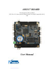
1.2. TI-DM3730-EM model
Figure 1.1 TI-DM3730-EM
Customers in batch purchase, the client can choose memory flash memory and processor
according to the product demand,Conventional models are as follows:
Model
Numbe r
Proce ssor
Spee d
(M Hz)
SDRAM
(M B)
NAND
Flash
(M B)
Te mpe rture
Analog
Vide o
Input
WIFI/
BT
SBC3530
OMAP
600
256
256
0℃-70℃
Y
N
-B1-1880
-LUAC0
SBC3530
-B1-1880
-LUEC0
3530
600
256
256
0℃-70℃
Y
Y
OMAP
3530
Chapter Two
2. TI-DM3730-EM Hardware introduction
2.1 TI-DM3730-EM hardware specification
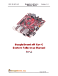
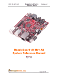
2.1.1
Block diagram
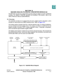
Figure 2.1 TI-DM3730-EM Block diagram
2.1.2
TI-DM3730-EM hardware parameter
6
SOM 3530
Ethe rne t port
Se rial port
USB Host
USB OTG
JTAG
Audio
VGA
AV/ S-Video v ide o
output
Vide o intput
SD socke t
fe rroe lectric storage
dev ice
OMAP3530
600MHz ARM Corte x™-A8 Core
NEO N™ SIMD coprocessor
430MHz TMS320C64x+ DSP
POWERVR
SG™
2D/3D
graphic
accelerator
RAM
128MByte/256MByte/512MByte DDR
Flash
128MByte/256MByte/512MByte/1GByte
Nand Flash
1x 10M/100M high performance Ethernet RJ45 interface
1x 5 wire RS232 interface(TX,RX,CTS,RTS,GND)
1x 3.3V 5 wire UART(TX,RX,CTS,RTS,GND)
4x USB 2.0 high speed Host
1x Internal USB 2.0 high speed Host
1x USB 2.0 high speed OTG(Can be used as Device)
1x 14Pin TI standard JTAG
1x 3.5mm audio output interface
1x Internal audio output interface
1x 3.5mm Microphone input port
Standard VGA output interface
Support below standard:
NTSC- J, M
PAL-B, D, G, H, I
PAL-M
CGMS-A
4 channels video input
Maximu m support:
4 wire CVBS
Or 1 wire CVBS、1 wire YPbPr
Or 1 wire CVBS、1 wire RGB (internal multiple synchronize
signal)
Or 2 wire CVBS、1 wire S-Video
Or 2 wire S-Video
CVBS support NTSC/PAL/SECAM standard
MMC/ SD/SDIO/SDHC sokect , Maximum support 32GByte
capacity
64Kbit/128Kbit/256Kbit/512Kbit unlimited erase ferroelectric
storage device
(optional device )
Encryption device
(optional device )
RTC
Ke y
LED indicator
Boot mode se lection
switch
Power
Extendable interface
Internal hardware encryption mechanism
Internal RTC,support CR1220 battery power supply
1x Programmable user interrupt key
1x RESET key
3x power indicator
2x Programmable indicator
1x 6 bit boot mode selection switch
1x 5V 2A DC socket
1x 5V 2A internal DC socket
1x 3.3V LCD module port (support touch)
1x 1.8V WIFI module port
1x 1.8V GOIO e xpand port
1x 1.8V GPMC high speed bus port
2.1.3
TI-DM3730-EM working environment
Env ironme nt
M in v alue
Typical v alue
Power supply
5V 0.3A
5V 0.5A(Remark 2) 5V 3.5A(Remark 1)
Power consumption
(working mode)
1.5W
Working
temperature
Max v alue
2.5W(Remark 2)
17.5W(Remark 1)
0°C
/
70°C
-40°C
/
80°C
(commercial level)
Working
temperature
(Industrial level)
Re mark 1: This is the average value When 4 channel USB interface charge to external
device and LCD, digital camera, WIFI module are connected.
Re mark 2: This is the average value when CPU under 600Mhz full speed working status,
and no external module is connected, USB port a re not charging to external device.
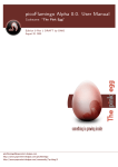
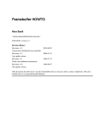
2.1.4
TI-DM3730-EM mechanical information
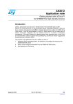
De sign purpose
PCB size
Single board compute r
Compatible
standard
EPIC standard
Installation
number
4.528 x 6.496 inch(115.00 x 165.00 mm)
hole 4 Nos
Figure 2.2 PCB machnical diagram
8
2.2 TI-DM3730-EM pin definition
2.2.1
Pin definition
Pin
Pin de scription
Re mark
number
CON1
5V DC power input port
DC-208 port , inside is positive and
outside is negative,Max current is 4A
CON2
10/100M Ethernet port
RJ45 port
CON3
5 channel RS232 port
CON4
USB OTG 2.0 port
CON5
3.5mm audio output interface
CON6
3.5mm Microphone port
CON7
MMC/ SD/SDHC/ SDIO socket
CON8
Two layer USB Host 2.0 port
CON9
Two layer USB Host 2.0 port
CON10
LCD module interface
CON11
VGA port
CON12
GPMC bus port
50Pin Pin plat cable port
BT1
RTC battery socket
Use CR1220 battery
J1~J4
SOM35 X interface
J5
5V 2A Internal DC input port
J6
5 wire UART interface
J7
14Pin TI standard JTAG
J8
Internal audio output interface
J9
Internal USB 2.0 high speed Host
J10
video input port
J11
WIF I/BT module port
J12
GPIO e xpandable port
3V/1.8V compatiable
50Pin Pin plat cable port
3.3V I/O
2.2.2
Key/ Switch specification
Ke y index
Ke y de scription
SW1
6 bit boot selection switch
SW2
Programmable interrupt key
SW3
Internal RESET key
2.2.3
Re mark
GPIO18
LED specification
LED Index
LED de scription
Re mark
D4
5V power supply indicator
D5
SOM3530 power supply indicator
D6
3.3V power supply indicator
D13
Programmable power management module indicator
GPIO126
D14
Programmable power management module indicator
GPIO127
2.1. Connector descrpt ion
1)
+5V DC input powe r port CON1
CON1 is+5V DC input power port, connector is DC-208, inside is positive, and outside is
negative. The MAX current is 4A
2)
Ethe rne t port socket CON2
This port is standard RJ45 10/100M self-adapter Ethernet port, it comes with data
indicator and channel indicator
3)
Digital switch SW1(Re mark:1:Move the Switch upward 0:Move the switch
downward)
10
Set the boot sequence of the TI-DM3730-EM through digital switch. Please check the
normal booting sequence according to TI-DM3730-EM system connection introduction.
Booting Sequence When SYS.BOOT[5] = 0
Me mory Booting Pre ferre d Orde r
sys_boot
[4:0]
First
Se cond
0b00000
Third
Fourth Fifth
Reserved(1)
0b00001
0b00010
0b00011
0b00100
OneNAND
USB
0b00101
MMC2
USB
0b00110
0b00111
MMC1
USB
Reserved(1)
0b01000
0b01001
0b01010
0b01011
0b01100
0b01101
XIP
USB
UART3
MMC1
0b01110
XIPwait
DOC
USB
UART3
0b01111
NAND
USB
UART3
MMC1
0b10000
OneNAND
USB
UART3
MMC1
0b10001
0b10010
MMC2
MMC1
USB
USB
UART3
UART3
MMC1
0b10011
0b10100
XIP
XIPwait
UART3
DOC
UART3
0b10101
0b10110
NAND
OneNAND
UART3
UART3
0b10111
0b11000
MMC2
MMC1
UART3
UART3
0b11001
0b11010
0b11011
XIP
XIPwait
NAND
USB
DOC
USB
0b11100
0b11101
0b11110
0b11111
USB
Reserved(1)
Fast
XIP
booting.devices)Wait
monitoring OFF (only
for GPdevices)
USB (only
on
GP
devices)
UART3 (only
on GP
MMC1
Booting Sequence When SYS.BOOT[5] = 1
Pe ripheral Booting Prefe rred Orde r
sys_boot
First
Se cond
[4:0]
0b00000
Third
Fourth
Fifth
Reserved(1)
0b00001
0b00010
0b00011
0b00100
USB
OneNAND
0b00101
0b00110
USB
USB
MMC2
MMC1
0b00111
0b01000
0b01001
Reserved(1)
0b01010
0b01011
0b01100
0b01101
USB
UART3
MMC1
XIP
0b01110
0b01111
USB
USB
UART3
UART3
MMC1
MMC1
XIPwait
NAND
0b10000
USB
UART3
MMC1
OneNAND
0b10001
USB
UART3
MMC1
MMC2
0b10010
USB
UART3
MMC1
0b10011
UART3
XIP
0b10100
0b10101
UART3
UART3
XIPwait
NAND
0b10110
0b10111
0b11000
UART3
UART3
UART3
OneNAND
MMC2
MMC1
0b11001
0b11010
USB
USB
XIP
XIPwait
0b11011
0b11100
USB
NAND
0b11101
0b11110
0b11111
DOC
DOC
Reserved(1)
Fast XIP booting.Wait
monitoring
ON (only for GP
devices)
SB (only on
GP
devices)
12
UART3 (only
on
GP
devices)
DOC
4)
Earphone output port CON5
Support stereo (Dual channel) audio output, this port is connected by speaker or
stereo earphone
5)
M icrophone input port CON6
Support Microphone input (Single channel) , ple ase connect microphone input
(Single channel) to this port.
6)
Re set Switch SW3
Press this key and release it, the TI-DM3730-EM board will enter POWER ON
RESET
status; the development board will be restart.
7)
SD card socket CON7
This socket support standard MMC/SD/SDHC/SDIO card, and compatible with
3V/1.8V. The system can boot from the SD/SDIO card.
8)
Se rial communication port CON3
Serial port is 5 wire RS232 port communication signal to other device. use
standard serial cable to connect to development board and other device which has
standard serial cable ( Such as PC)
9)
VG A port CON11
Standard VGA output interface, support all the VESA standard resolution. TIDM3730-EM development board connected with LCD monitor and CRT monitor by
this port.
10) LCD conne ctor CON10
This connector is 50 pin plat cable connector, include 24 bit true color CMOS
display signal and touch screen interface, all the touch screen resolution can achieve
1920x1080.
11) AV connector(CVBS)/ SVIDEO OUT socke t J12
The AV connector support CVBS and S-VIDEO output, user can select either one
as output
12) USB OTG 2.0 port CON4
The port is MINI type USB Host/Device multiple xing port, it can connect with
standard USB Device product, support OTG and HOST mode ( Use different type of
cable).
13) USB Host 2.0 port CON8/ CON9
USB 2.0 high speed HOST (Every port will provide standard 500mA po wer
supply)
14) SDIO port /WIFI expand module port J11
Extend port support expandable signal, when customer need these signal, they
can connect to corresponding socket to get the signal.
15) GPIO expandable port J12
General input/ output GPIO, every GPIO port can set to input or output by
software. Pin definition please refer to 2.7.11
14
16) SPI e xpandable port J12
Serial peripheral port SPI, Pin definition please refer to 2.7.14
17) 4 channe l video output interface J10
4 channe l video input max support :
4 channel CVBS or 1 channel CVBS, 1 channel YPbpr or 1 channel CVBS, 1
channel RGB (internal multiplexing synchronous sig nal) or 2 channel CVBS, 1
channel S-Video or 2 channels S-Video
Further more, CVBS support NTSC/ PAL / SECAM
18) D4、D5power indicator
When TI-DM3730-EM correctly input DC +5V po wer supply, the indicator will po
wer on, and indicate power supply is properly. If the indicator not on, please shut
down the power supply and find out the problem
2.4 TI-DM3730-EM pin definition
J1~J4 SOM 35x interface
This interface is used to connect SOM 35x module
J5 powe r manage ment module interface
This module is use d to conne ct power manage ment module
Pin
Function description
1
Grand
2
DC 5V input
3
DC 5V input
4
Grand
Re mark
J6 UART3 interface
This port is used to connect UART3
Pin
Function description
Re mark
1
3.3V I/O reference voltage output
I/O reference voltage
2
Grand
3
CTS
3.3V I/O
4
RTS
3.3V I/O
5
TX
3.3V I/O
6
RX
3.3V I/O
J7 TI-DM3730-EM JTAG debug interface
This port is used to debug TI-DM3730-EM and internal DSP
Pin
Function description
Re mark
1
TMS
1.8V I/O
2
nTRST
1.8V I/O
3
TDI
1.8V I/O
4
Grand
5
1.8V I/O reference voltage output
I/O reference voltage
6
/
Incorrect
protection Pin
7
TDO
1.8V I/O
8
Grand
9
RTCK
10
Grand
11
TCK
12
Grand
13
EMU0
14
EMU1
1.8V I/O
1.8V I/O
1.8V I/O
1.8V I/O
16
insertion
J8 Internal audio output interface
This port is used for output to additional amplifier module .
Pin
Function description
Re mark
1
Left audi o channel
25mW
output
2
Left
Grand
3
Right
Grand
4
Right
audio
channel
25mW
output
J9 internal USB Host interface
This port is multiple xing with CON9 and USB4
Re mark :This interface is multiple x with USB4 (CON 9)
Pin
Function description
Re mark
1
5V power output
Used for USB power supply
2
DM
USB data difference (Negative)
3
DP
USB data difference (Positive)
4
Grand
J10 Video input port
This port is used to v ide o input
Pin
Function description
1
The 4th video input channel:CVBS/Y input
2
Virtual signal grand
3
The 3 video input channel: CVBS/Pr/R/C input
4
Virtual signal grand
5
6
7
8
Re mark
th
The 4 channel grand
rd
The 3rd channel grand
The 2nd video input channel:CVBS/Y input
Virtual signal grand
The second signal grand
st
The 1 video input channel:CVBS/Pb/B/C input
Virtual signal grand
The first channel grand
J11 WIFI module expand inte rface
Pin
Function description
Re mark
1
3.3V power output
2
Grand
3
1.8V I/O reference voltage output
4
Grand
5
SYS_nRESPWRO N
6
MMC2_CMD
1.8V I/O
7
MMC2_CLK
1.8V I/O
8
MMC2_DAT1
1.8V I/O
9
MMC2_DAT0
1.8V I/O
10
MMC2_DAT3
1.8V I/O
11
MMC2_DAT2
1.8V I/O
12
MMC2_DAT5/GPIO137
1.8V I/O
13
MMC2_DAT4/GPIO136
1.8V I/O
14
MMC2_DAT7/GPIO139
1.8V I/O
15
MMC2_DAT6/GPIO138
1.8V I/O
16
MCBSP3_DX/ UART2_CTS
1.8V I/O
17
MCBSP3_FSX/ UART2_RX
1.8V I/O
18
MCBSP3_CLKX/ UART2_TX
1.8V I/O
19
MCBSP3_DR/ UART2_RTS
1.8V I/O
20
MCBSP1_DR/GPIO159
1.8V I/O
21
MCBSP1_DX/GPIO158
1.8V I/O
22
MCBSP1_CLKX/GPIO162
1.8V I/O
23
MCBSP1_FSX/GPIO161
1.8V I/O
24
/
/
18
I/O reference voltage
J12 GPIO e xpand interface
Pin
Function description
Re mark
1
3.3V power output
2
Grand
3
1.8V I/O reference voltage output
4
Grand
5
SYS_CLKO UT1/GPIO10
1.8V I/O
6
SYS_nRESPWRO N
1.8V I/O
7
SYS_CLKO UT2/GPIO186
1.8V I/O
8
MCBSP1_CLKR/GPIO156
1.8V I/O
9
HSUSB1_D0/MCSPI3_SIMO/GPIO14
1.8V I/O
10
MCBSP1_FSR/GPIO157
1.8V I/O
11
HSUSB1_D1/MCSPI3_SOMI/GPIO15
1.8V I/O
12
HSUSB1_CLK/GPIO13
1.8V I/O
13
HSUSB1_D2/MCSPI3_CS0/GPIO16
1.8V I/O
14
HSUSB1_STP/GPIO12
1.8V I/O
15
HSUSB1_D7/MCSPI3_CLK/GPIO17
1.8V I/O
16
Grand
17
3V3_I2C3_SCL
3.3V I/O
18
AV/SVIDEO_Y
CVBS output /S-Video Y output
19
3V3_I2C3_SDA
3.3V I/O
20
SVIDEO_C
S-Video C output
I/O reference voltage
Chapter Three
3.
TI-DM3730-EM basic
function
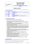
3.1. TI-DM3730-EM computer
system
Video output
Audio
interface
Ethernet
interface
LCD
Camera
TIDM3730-EM
SD card
WIF I
USB Host
USB
Disk
Keyboard
Standard acce ssorie s
1) DV +5V power
2) Standard cross serial cable, both side is female type
3) One DVD for software
4) Ethernet cable
5) SD card
Optional acce ssorie s
1) USB keyboard
2) USB mouse
3) Audio connector (Dual stereo)
4) 4 port USB integrator
20
Mouse
3.2. TI-DM3730-EM connection configuration
3.2.1. External port connection
1)
Power off
Before connect/disconnect each device, the power need to be off, and the static
damage need to be prevented.
2)
Prepare EM A TI-DM3730-EM
Check whether TI-DM3730-EM board is damaged when user
get it.
3)
Connect serial communication cable
Connect serial cable to TI-DM3730-EM socket CO N3, the other side connect to
the PC
serial port (Normally is COM1 port)
4)
Connect to LCD monitor
Prepare one VESA standard resolution, VGA interfaces LCD. Connect the LCD
VGA port with TI-DM3730-EM CO N11 port by VGA cable.
5)
Connect LCD touch screen
Connect the LCD touch screen with TI-DM3730-EM CO N10 interface by FPC
cable. The gold finger connector of the FPC and CON10 of TI-DM3730-EM are both
downwards
Notice: Please do not misconnect 3.3V LCD CON10 connector with 5VGPMC
connector, it will case great damage to the board.
6)
Connect ke yboard and mouse
Connect the USB port keyboard and mouse to USB host
7)
Insert SD card.
Insert the proper working SD card to TI-DM3730-EM CON4 socket,
8)
Se t digital switch J12 (Re mark: 1 : Switch upward, 0: switch downward )
Set
Se que nce
First
dev ice
Se cond
dev ice
Third
dev ice
Fourth
dev ice
111100
NAND
USB
UART3
MMC1
111101
USB
UART3
MMC1
NAND
000111
UART3
MMC1
111100,
checking
the
digital
switch
to
(1-6):
sequence
is
NANDFLASH->USB->UART3->MMC1
Set
the
digital
switch
(1-6):
111101,
checking
sequence
will
be
USB->UART3->MMC1-> NANDFLASH
Set the digital switch (1-6): 000111, check sequence will be UART3 MMC1
3.2.2 The sequence to power on the system
1) Power on pe ripheral power supply
Please power on the peripheral device step by step, such as LCD display, USB
integrator.
2) Connect and power on the TI-DM3730-EM power
Use TI-DM3730-EM standard 5V power supply, connect it with the 220V
outlet and power on. Connect the 5V output power to power socket CON1.
3) Re movable storage device synchronization
If you use the USB interface, hot swappable storage device to the written
documents which can then enter the Linux command line console sync command, so
that the data stored in the cache to write all these devices.
22
3.2.3 The sequence to power off the system
1)
Remove the portable storage device
2)
Shut down system power
3)
Shut down TI-DM3730-EM po wer supply system.
4)
Shut down the power for peripheral
Chapter Four
4. TI-DM3730-EM Linux system
configuration
4.1. System booting method and procedure
There are two common ways to start on TI-DM3730-EM:
TI-DM3730-EM normally has t wo booting method:
Boot from Nand flash
Boot from SD card
Starting from the SD card storage capacity is available to a more flexible configuration,
while the flexibility to replace the system software.
Two channels are used to start the SD card. SD card launch is a complete system where
all start from the SD, which started from the SD card Nandflash boot into U-Boot, by
command of the four SD Kari syste m image files downloaded to the memory, and then
programmed to Nandflash on, and then back on after power without SD, a complete
system where you can start from Nandflash. Therefore, format partitions on the SD card is
very important to start the system,the specific realization of the system can view the 6.2.1
start making SD card.
4.1.1. The syste m boot process:
Detection Nandflsah / SD card. From Nandflash / SD card Fat32 partition
start address unit X-Loader program to the memory, and begin
implementation of the X-Loader.
24
X-Loader do some initialization work first and then ,read the U-Boot to
memory from Nandflash/SD card Fat32 partition ,and begin execute the
U-Boot.
U-Boot read Fat32 partition boot parameters from,and then read into the
Linux kernel uImage to TI-DM3730-EM me mory,decompress and
running the kernel uImage.
Re-initialize
TI-DM3730-EM after
Linux kernel
start , then
load
NandFlash file system stored on SD cards or EXT3 partition file system, file
system execute
program and start the console.
4.1.2. SD card boot proce ss
1)
Ready to start the system image file (MLO, u-boot.bin, uImage, rootfs), and put
the three image files into the SD card FAT32 part ition, the rootfs on SD card
EXT3 partition (the CD-ROM file system archive, extract the Linux systems to SD
card EXT3 partition).
2)
Connect the hardware.
3)
Start the Hyper Terminal on the PC.
4)
Link and connect the power of TI-DM3730-EM.
After normal boot the system, you can see the target board in HyperTerminal
startup information, login as super-character display terminal, enter the user
name "root", press enter to access Linux systems.
4.1.3. Nandflash boot proce ss
1)
Ready to start the system image file (MLO, u-boot.bin, uImage, ubi.img), and put
four image files into SD card FAT32 partition.
2)
Program the boot system image file to Nandflash.
3)
Connecting hardware(without SD).
4)
Start the Hyper Terminal on the PC.
5)
Link and connect the power of TI-DM3730-EM.
6)
After normal boot the system, you can see the target board in HyperTerminal
startup information, login as super-character display terminal, enter the user
name "root", press enter to access Linux systems.
4.2. Display setting
TI-DM3730-EM supports multiple display output, DVI output is from the system
default. If users want to use the LCD output, or want to change the resolution, the user
needs to modify U-Boot in the corresponding parameters。
Refresh rate of resolution of the corresponding General :
Re solution
480x272
Re fre sh rate
60
800x480
800x600
60
60
1024x768
1280x720
60
60
1366x768
1280x1024
60
50
1440x900
1920x1080
50
30
4.2.1 VGA port display:
# setenv dvimode 1024x768MR-16@60
#setenv defaultdisplay dvi
setenv dvimode 1024x768MR-16@60 mean the display mode is VGA 、 1024x768
resolution、16bit and fresh rate 60
26
4.2.2 4.3 inch touch screen display
# setenv dvimode
# setenv defaultdisplay lcd043
The meaning of parameters is not set to DVI display mode of resolution, color bit, and
refresh rate, then modify the default display mode into 4.3 -inch touch screen.
4.2.3 7 inch touch screen display
# setenv dvimode
# setenv defaultdisplay lcd070
The meaning of parameters is not set to DVI display mode of resolution, color bit, and
refresh rate, then modify the default display mode into 7-inch touch screen.
4.3. DEMO software demonstration
Copy CDROM Demo folder to /home/ema/ directory, (this directory is under /mnt/
hgfs/share directory)
#cd /mnt/hgfs/share
#sudo cp –a Demo /home/ema/
Copy the mirror of the demo and system to the SD card which already been
formatted.
#cd /home/ema/ Demo
#sudo cp MLO /media/boot
#sync
#sudo cp u-boot.bin /media/boot
#sudo cp uImage /media/boot
#sudo tar jxvf evm_fs.tar.bz2
–C /media/rootfs
#umount /media/boot
#umount /media/rootfs
Disconnect the USB connection, remove SD card from development board,,
power on and start the development board.
4.3.1 3D Demo
Enter U-BOOT setting parameter
OM AP3 Stalker # setenv vram 12M omapfb.vram=0:12M
OM AP3 Stalker # saveenv
Saving Environment to NAND...
Erasing Nand...
Erasing at 0x260000 -- 100% complete.
Writing to Nand... done
OM AP3 Stalker # boot
Starting Connection Manager
.-------.
|
|
.-.
| | |-----.-----.-----.| | .----..-----.-----.
|
|
| __ | ---'| '--.| .-'|
|
|
| | | | |
|--- || --'| | | ' | | | |
'---'---'--'--'--. |-----''----''--' '-----'-'-'-'
-' |
'---'
The Angstrom Distribution stalker ttyS2
Angstrom 2009.X-stable stalker ttyS2
stalker login: root
User ID :root ,password is empty, press “Enter” directly to sign in
root@be agle board:~# cd /opt/gfxsdkdemos/ogles
root@be agle board:/opt/gfxsdkde mos/ogles# ls
Balloon_fixed.pod
OGLESOptimizeMesh
SphereOpt_fixed.pod
Balloon_float.pod
OGLESParticle s
SphereOpt_float.pod
ChameleonScene.pod
OGLESPhantomM ask
Sphere_fixed.pod
ChameleonScene_Fixed.pod OGLESPolyBump
Sphere_float.pod
Mesh_fixed.pod
OGLESShadowTe chniques
balloon.pvr
Mesh_float.pod
OGLESSkybox
o_model_fixed.pod
OGLESChame le onMan
OGLESTriline ar
o_model_float.pod
OGLESCove rflow
OGLESUserClipPlane s
skybox1.pvr
OGLESEv ilSkull
OGLESVase
skybox2.pvr
OGLESFive Sphe res
PhantomMask_fixed.pod
skybox3.pvr
OGLESFur
PhantomMask_float.pod
skybox4.pvr
OGLESLighting
Scene_fixed.pod
skybox5.pvr
OGLESM ouse
Scene_float.pod
28
skybox6.pvr
s/ogles4.3.2 Quake3
Enter U-BOOT setting parameter
OM AP3 Stalker # setenv vram 12M omapfb.vram=0:12M
OM AP3 Stalker # saveenv
Saving Environment to NAND...
Erasing Nand...
Erasing at 0x260000 -- 100% complete.
Writing to Nand... done
OM AP3 Stalker # boot
Starting Connection Manager
.-------.
|
|
.-.
| | |-----.-----.-----.| | .----..-----.-----.
|
|
| __ | ---'| '--.| .-'|
|
|
| | | | |
|--- || --'| | | ' | | | |
'---'---'--'--'--. |-----''----''--' '-----'-'-'-'
-' |
'---'
The Angstrom Distribution stalker ttyS2
Angstrom 2009.X-stable stalker ttyS2
stalker login: root
User ID :root ,password is empty, press “Enter” directly to sign in
root@stalke r:~# cd /usr/lib/quake3/
root@stalke r:/usr/lib/quake3# ./run.sh
Execute the script and user can see the game interface from the VGA monitor,
Select “ SINGLE PLAYER “ to enter the game map, then select CHOOSE
“ LEVEL FIGHT “ ->DIFFICULTY FIG HT to play the game. Press “ ESC ” on the
keyboard which is connecting to the development board. Then select EXIT
GAME ->YES, because the console has been screened, so we can control
through the serial port terminal. We can also finish the game by press “ CTRL +
C “ on the keyboard of the PC.
4.3.3 DVSDK
Enter U-BOOT setting parameter
OM AP3 Stalker # setenv mmcargs 'setenv bootargs console=${console} vram=${vram}
omapfb.mode=dvi:${dvimode} omapdss.def_disp=${defaultdisplay} root=${mmcroot}
init=/init mpurate=${mpurate} rootfstype=${mmcrootfstype} boardmodel=${boardmodel}
mem=99 M@0 x80000000 mem=128M@0x88000000'
OM AP3 Stalker # saveenv
Saving Environment to NAND...
Erasing Nand...
Erasing at 0x260000 -- 100% complete.
Writing to Nand... done
OM AP3 Stalker # boot
Starting Connection Manager
.-------.
|
|
|
|
|
|
|
.-.
|-----.-----.-----.| | .----..-----.-----.
|
| __ | ---'| '--.| .-'|
|
|
| |
|--- || --'| |
|
| ' ||||
'---'---'--'--'--. |-----''----''--' '-----'-'-'-'
-' |
'---'
The Angstrom Distribution stalker ttyS2
Angstrom 2009.X-stable stalker ttyS2
stalker login: root
User ID :root ,password is empty, press “Enter” directly to sign in
root@be agle board:/opt/dv sdk/omap3530#
root@be agle board:/opt/dv sdk/omap3530#
./loadmodules.sh
./decode
-v ./data/videos/davincieffect_ntsc_1.264
4.3.4 Video input demonstration
Video input demo is play DVDS CDS,Through the TI-DM3730-EM development
board VGA display interface。The DVD player need us take CVBS signal and Grounding
signall connect to TI-DM3730-EM J8 interface foot 7 and foot 8 ,The program channel
default selection is 0,The other program channel number of Corresponding simulation
channel and Video mode choice, Please refer to The form below:
30
Mode
CVBS
S-video
Analog Channel and Video Mode Selection
Input(s)
Program Cvbs
Cvbs
S-v ide o
Se le cte d
channe l
GND
Y
number
S-v ide o
C
S-v ide o
GND
VI_1_A(default)
0
PIN7
PIN8
/
/
/
VI_2_A
1
PIN5
PIN6
/
/
/
VI_3_A
2
PIN3
PIN4
/
/
/
VI_4_A
3
PIN1
PIN2
/
/
/
VI_2_A(Y),
VI_1_A(C)
4
/
/
PIN5
PIN7
PIN8
VI_2_A(Y),
VI_3_A(C)
5
/
/
PIN5
PIN3
PIN4
VI_4_A(Y),
6
/
/
PIN1
PIN7
PIN8
VI_1_A(C)
VI_4_A(Y),
7
/
/
PIN1
PIN3
PIN2
VI_3_A(C)
Vide o Input DEM O Compile r Steps:
a)
Copy analog_vi_demo.tar.bz2 to /home/ema/ directory (Compressed files are in
share directory)
ema@ema3530:~$ cd /mnt/hgfs/share
ema@ema3530:/mnt/hgfs/share$ cp analog_vi_demo.tar.bz /home/ema/
b)
Un zip analog_vi_demo.tar.bz2 into present Folder
ema@ema3530:~ $ cd /home/ema/Source
ema@ema3530:~ $ sudo tar analog_vi_demo.tar.bz
ema@ema3530:~ cd analog_vi_demo/video
c)
make clean command clean up earlier Compilation files
ema@ema3530:~/analog_vi_demo/video$ make clean
Cleaning binaries...
d)
then. Configuration and compiled .modify Cross-compilation tool chain libraries
path in Makefile
LDFLAGS = -L/usr/local/arm/arm-2009q1/arm-none-linux-gnueabi/libc/lib/
Modify its kernel code paths and Cross-compilation tool chain libraries path in Rules.make
file
KER NEL_D IR = /home/ema/linu x-03.00.01.06
CROSS_COMPILE = /usr/local/arm/arm-2009q1/bin/arm-none-linux-gnueabiema@ema3530:~/analog_vi_demo/video $ make
After the completion of the compiler,It will Generate many Executable file in Bin directory,
put saMmapLoopback in Development board systems and running on.
ema@ema3530:~ /analog_vi_demo/video /bin$ cp saMmapLoopback /mnt/hgfs/share
saMmapLoopback.c program adopted by default program channel “0”, If want to modify
the program channel, modify“capt_input = 0”corresponding program channel numbe In
the main () function,Save and exit。Recompile again.
Development board operation procedure s:
power on and Start development board,Enter your user name and password to
enter a file system.
Starting Connection Manager
.-------.
|
|
|
|
.-.
|-----.-----.-----.| | .----..-----.-----.
|
| __ | ---'| '--.| .-'|
|
|
|
| | | | |
|--- || --'| | | ' | | | |
'---'---'--'--'--. |-----''----''--' '-----'-'-'-'
-' |
'---'
The Angstrom Distribution stalker ttyS2
Angstrom 2009.X-stable stalker ttyS2
stalker login: root
user name:root , password
is empty,Press enter can login。
execute “saMmapLoopback”.
root@be agle board:~# ./saMmapLoopback
[
44.942169] tvp514x 2-005d: tvp5146m2 found at 0xba (OMAP I2C adapter)
Capture: Opened Channel
Capture: Current Input: COMPOSITE
Capture: Input changed to: COMPOSITE
Capture: Current standard: NTSC
Capture: Capable of streaming
Capture: Number of buffers request = 2
Capture: Number of requested buffers = 2
Capture: Init done successfully
32
Display: Opened Channel
Display: Capable of streaming
Display: Number of buffers request = 2
Display: Number of requested buffers = 3
Display: Init done successfully
Display: Stream on...
Capture: Stream on...
4.3.5 USB camera demonstration
USB camera demonstration, It need to make a new SD card system , then.take
MLO,u-boot.bin,uImage of Camera_FS Folder.into SD card
FAT32 partition ,
camera_fs.tar.bz2 unzip to Sd card EXT3 partition(See user manual 6.2. Linux
Syste m mirroring update)
Power on and Start development board,Enter your user name and password to
enter a file system。
Starting Connection Manager
.-------.
|
|
.-.
| | |-----.-----.-----.| | .----..-----.-----.
|
|
| __ | ---'| '--.| .-'|
|
|
| | | | |
|--- || --'| | | ' | | | |
'---'---'--'--'--. |-----''----''--' '-----'-'-'-'
-' |
'---'
The Angstrom Distribution stalker ttyS2
Angstrom 2009.X-stable stalker ttyS2
stalker login: root
user name:root ,The password is empty,Press enter can login。
Enter dev/video files and Check video equipment files,Then insert USB
cameras,Check the video Additional equipment files(Note the device name,
when we modify Script,we will use it)
。
root@be agle board:~# cd /dev
Enter mjpg-streamer-r63 directory, modify mjpg-streamer.sh of equipment
filename,The default is/dev/dev/video0 and/video2 。(modify the device name,
according to the above additional the video equipment filename)
root@be agle board:~# cd mjpg-streamer-r63
root@be agle board:~/mjpg-stre amer-r63# vi mjpg-streamer-r63.sh
./mjpg_streamer -o "output_http.so -w `pwd`/www -p 8080" -i "input_uvc.so -d /dev/video0
-r 640x480 -f 30" &
./mjpg_streamer -o "output_http.so -w `pwd`/www -p 8081" -i "input_uvc.so -d /dev/video2
-r 640x480 -f 5" &
8080 and 8081 is port Number,/ dev/dev/video0 and/video2 is corresponding to the USB
camera equipment filename , 640x480 is resolution 。 This script is also testing two
cameras。If testing one,One can shield。
Executive mjpg-streamer.sh scripts
root@be agle board:~/mjpg-stre amer-r63#./ mjpg-streamer-r63.sh
root@beagleboard:~/mjpg-streamer-r63# MJPG Streamer Version.: 2.0
i: Using V4L2 device.: /dev/video2
i: Desired Resolution: 640 x 480
i: Frames Per Second.: 5
i: Format............: MJPEG
o: www-folder-path...: /home/root/mjpg-streamer-r63/www/
o: HTTP TCP port.....: 8081
o: username:password.: disabled
o: commands..........: enabled
Connect NetworkCable and Check development board IP。
root@be agle board:~/mjpg-stre amer-r63#ifconfig
eth0
Link encap:Ethernet HWaddr 02:00:39:BC:00:04
inet addr:192.168.1.180 Bcast:255.255.255.255 Mask:255.255.255.0
UP BROADCAST RUNNING MULTICAST MT U:1500 Metric:1
RX packets:3219 errors:0 dropped:0 overruns:0 frame:0
TX packets:57 errors:0 dropped:0 overruns:0 carrier:0
collisions:0 txqueuelen:1000
RX bytes:357335 (348.9 KiB) TX bytes:8662 (8.4 KiB)
Interrupt:179
34
Open the PC browse(
r Recommended for use Firefox), Input development board
IP and port number,like http://192.168.1.180:8081/ ,
choose”Stream”->”here”or“Javascript”->”here” in the web,No w You can see the
camera image acquisition。
4.3.6 Play video demonstration
Power on and start Development board,Enter your user name and password to
enter a file system。
Starting Connection Manager
.-------.
|
|
.-.
| | |-----.-----.-----.| | .----..-----.-----.
|
|
| __ | ---'| '--.| .-'|
|
|
| | | | |
|--- || --'| | | ' | | | |
'---'---'--'--'--. |-----''----''--' '-----'-'-'-'
-' |
'---'
The Angstrom Distribution stalker ttyS2
Angstrom 2009.X-stable stalker ttyS2
stalker login: root
user name:root ,The password is empty,Press enter can login。
we can see“720x480Hotplace.avi” in current directory ,use mplayer broadcast。
root@be agle board:~# mplayer 720x480Hotplace.avi -ao alsa
Chapter Five
5. Construct Embedded Linux software
development environment
5.1 Linux software development environment
description
Before using the development board, user need to build the software development
environment for TI-DM3730-EM.
As Linu x is open source, user can do wnload the soft ware for TI-DM3730-EM
board from internet free. And after some necessary modification and set the
configuration, that software can run on TI-DM3730-EM board. Our CD-ROM already in
clude those contents,
TI-DM3730-EM
mplete
development
soft ware
board
provides
a
co
develop ment environment, after the installation acco rding
to the sy stem instruction, users no need to install unnecessary content and software
and start the development immediately. The development environment is normally a PC
with Windo ws XP operating syste m
User can visit our website: http://code.google.com/p/ema3530/ to get updated
software package and information
5.2 Build the software development environment
5.2.1
Install the VMare -workstation-6.5.0
36
1 、 Double click VMare- workstation-6.5.0-118166.exe to enter below installation
interface.
Figure 5.1
2、Clicks ne xt, enter the interface as picture 4.2, and select Typical install.
Figure 5.2
3、Click “ Ne xt” button, and click “change” button, select the installation path and
click “ne xt” button as picture 4.3 sho w.
Figure 5.3
Figure 5.4
38
Figure 5.5
4、Click “install” and start the installation as picture 4.6 sho w.
Figure 5.6
5、After installation there will be a pop-up message as 4.7 sho w, please “YES” and
restart the computer
Figure 5.7
6、Finally the VMware- workstation icon be generated on the desktop.
Figure 5.8
5.2.2
Ubuntu installation
We provide a Ubuntu syste m in the CD. User only needs to copy it to the PC.
The installation step as belo w:
1)
Open the CD-ROM, copy and deco mpress the v m.7 z file as picture 4.9 sho w.
Figure 5.9
40
2)
Open VMware- workstation icon ( As picture 4.10 sho w)
Figure 5.10
3)
Open File as picture 4.11 show
Figure 5.11
4)
Select the v m.7 z file as picture 4.12 show
Figure 5.12
5)
Select the Green triangle on the up-left side, and start Ubuntu as picture 4.13
show.
Figure 5.13
42
6)
Log in Ubuntu as picture 4.14 sho w:
Figure 5.14
Input the user name: ema
7)
pass word:
Log in success as picture 4.15 sho w.
Figure 5.15
e ma
5.2.3
1)
Set the file share configuration for Virtual machine
and the host.
Set the virtual ma chine. Select VM/Settings or Ctrl+D as belo w
Figure 5.16
2)
Select the “Shared Folders” under “Options”, as picture 4.17 show
Figure 5.17
44
3)
The Linux syste m of the Virtual Machine can acces s shared folder. The path of
those file which will be access by Linu x is “/ mnt/hgfs”, set the shared folder ’s
path and name at the pop-up windo ws.
Figure 5.18
4)
After set the configuration, add the path of the shared folder automatically as
below:
Figure 5.19
5)
After the installation finished, under /mnt/ directory there wi ll be a ne w hgfs
folder, the folder is used to communication bet ween the Virtual machine and
Host.
Command is :
#cd /mnt/hgfs
#ls
This command will he lp user to check the shared folder.
5.2.4
1)
Build cross compiler
Create folder arm under /usr/local/
Command is:
#su
#ema
#mkdir /usr/local/arm
2)
Copy arm-2009q1-126-arm-none-linux-gnueabi-i686-pc-linux-gnu.tar.b z2 to
/home/ema/tool
(arm-2009q1-126-arm-none-linux-gnueabi-i686-pc-linux-gnu.tar.bz2 already
been move to /mnt/hgfs/share)
Command is:
#cd /mnt/hgfs/share
#cp
arm-2009q1-203-arm-none-linux-gnueabi-i686-pc-linux-gnu.tar.bz2
/home/ema/tool
3)
Decompress to the /usr/local/ar m folder
Command is:
46
#cd /home/ema/tool
#tar
jxvf
arm-2009q1-203-arm-none-linux-gnueabi-i686-pc-linux-gnu.tar.bz2
–C
/usr/local/arm
4)
Set the environment variable
Command is:
#export PATH= /usr/local/arm/arm-2009q1/bin:$PATH
5)
Check the environment variable
Command is:
#echo $PATH
5.3
Serial terminal software use
the Windows XP desktop, select the menu: Start -> All Programs ->
Accessories -> Communications -> HyperTerminal
In the "Connection Description" window, enter the name: ema, select "OK"
In the "Connect to" window to confirm the "Connect using" item as "COM1",
select "confirm"
In the "COM1 Properties" window set: second digit = 115200, data bits = 8,
parity = none, stop bits = 1 Flow control = None, select "OK"
the desktop will automatically open "ema-Super Terminal" window
In the "ema-Super Terminal" windo w, select the menu: File -> Exit, when
asked whether the stored connections to answer "yes"
Expand the WindowXP desktop and right click the individual: Start -> All
Programs -> Accessories -> Communications -> HyperTerminal -> ema,
select "Send to desktop shortcut" back to the desktop to the newly created
connection renamed bit " Connect ema "Start HyperTerminal
In Window XP desktop double-click the "Connect ema" icon to start the
HyperTerminal
It is recommended that you use the ZOC Terminal, software on the CD in the
Linux\Tools\ZOC folder, there are configuration instruction s.
5.4
Mount t he network f ile system NFS
NFS service is to host a directory can be mounted through the network to other
computers, and other computer as a directory. In embedded development, through the
NFS can be easily modified files will be transferred to the target board via NFS.
Ubuntu default is no NFS service, so needs its own installation
1、Install the version of NFS Services
ema@ema3530:~$ sudo apt-get install nfs-kernel-server
2、Modify the NFS configuration files,vim /etc/exports
ema@ema3530:~$ vim /etc/exports
Add the NFS in the file directory format is as follows, and save the file e xit.
/home/ema/nfs_share *(rw,sync,no_root_squash)
3、Established in the root directory of the shared directory, and create a test file in directory
ema@ema3530:~$ mkdir /home/ema/nfs_share
ema@ema3530:~$ touch /home/ema/nfs_share/test
4、Restart NFS
ema@ema3530:~$ sudo /etc/init.d/nfs-kernel-server restart
48
5、look over the host IP
ema@ema3530:~$ ifconfig
6、Mount a local directory, test NFS
ema@ema3530:/$ sudo mount 192.168.1.162:/home/ema/nfs_share/ /tmp/
[sudo] password for ema:
ema@ema3530:/$ ls /tmp/
aaa
ema@ema3530:/$ sudo umount /tmp/
ema@ema3530:/$ ls /tmp/
gconfd-ema
keyring-QhwEr7
orbit-ema
ssh-oHsGDk5300
VMwareDnD
vmware-root
7、Target boards need to install nfs-utils-client
root@beagleboard:~# opkg install nfs-utils-client
Installing nfs-utils-client (1.1.2-2.1) to root...
Downloading
http://www.angstrom-distribution.org/feeds/2008/ipk/glibc/armv7a/base/nfs-utils-client_1.1
.2-2.1_armv7a.ipk
Configuring nfs-utils-client
8、Target board through the NFS mount the host dir ectory
root@beagleboard:~# mount 192.168.1.162:/home/ema/nfs_share /tmp/
Can't set permissions on mtab: Operation not permitted
root@beagleboard:~# ls /tmp/
test
Chapter Six
6. Build the software development
environment
6.1 System compile
6.1.1 First stage code x-loader compile
First set up environment variables, command is :
ema@ema3530:~$ export PATH= /usr/local/arm/arm-2009q1/bin:$PATH
e)
Copy x-loader.tar.bz2 to
/home/ema/ source directory (the files are in the
share disk directory)
ema@ema3530:~$ cd /mnt/hgfs/share
ema@ema3530:/mnt/hgfs/share$ cp x-loader.tar.bz2 /home/ema/Source
f)
Decompress x-loader.tar.bz2
to the current folder
ema@ema3530:~ $ cd /home/ema/Source
ema@ema3530:~/Source$ sudo tar jxvf x-loader.tar.bz2
ema@ema3530:~/Source$ cd xloader
g)
make distclean
:clear the previous build dependency files generated
ema@ema3530:~/source/xloader$ make CROSS_COMPILE=ar m-none-linux-gnueabiARCH=arm distclean
find . -type f \
50
\( -name 'core' -o -name '*.bak' -o -name '*~' \
-o -name '*.o'
-o -name '*.a' \) -print \
| xargs rm -f
find . -type f \
\( -name .depend -o -name '*.srec' -o -name '*.bin' \) \
-print \
| xargs rm -f
rm -f *.bak tags TAGS
rm -fr *.*~
rm -f x-load x-load.map
rm -f include/asm/proc include/asm/arch
rm -f include/config.h include/config.mk
h)
Then configure and compile
ema@ema3530:~/source/xloader$ make
CROSS_COMPILE=ar m-none-linux-gnueabi-
ARCH=arm sbc3530_config
rm -f include/config.h include/config.mk
Configuring for omap3530beagle board...
ema@ema3530:~/source/xloader$ make CROSS_COMPILE=ar m-none-linux-gnueabiARCH=arm
Compilation is completed, xloader directory will generate a new x-load.bin.
ema@ema3530:~/source/xloader$ ls
arm_config.mk config.mk drivers
board
common
i)
cpu
disk
fs
lib
README
Makefile
scripts x-load
include mkconfig signGP
into SD card startup procedures:MLO
ema@ema3530:~/source/xloader$ ./ signGP
ema@ema3530:~/source/xloader$ ls
Syste m.map
x-load.bin
x-load.map
arm_config.mk cpu
include
board
lib
disk
common
drivers
config.mk
fs
Makefile
README
scripts
x-load
x-load.bin
signGP
mkconfig System.map
x-load.bin.ift
x-load.map
ema@ema3530:~/source/xloader$ cp x-load.bin.ift MLO
6.1.2 Second code u-boot compile
First set up environment variables, command is:
ema@ema3530:~ $ export PATH= /usr/local/arm/arm-2009q1/bin:$PATH
a)
Copy u-boot-release.tar.bz2 to
/home/ema/ source directory (the files are in
the share disk directory)
ema@ema3530:~$ cd /mnt/hgfs/share
ema@ema3530:/mnt/hgfs/share$ cp u-boot-release.tar.bz2 /home/ema/Source
b)
decompress u-boot-release.tar.bz2 to the current folder
ema@ema3530:~$ cd /home/ema/Source
ema@ema3530:~/Source$ sudo tar jxvf u-boot-release.tar.bz2
ema@ema3530:~/Source$ cd u-boot-release
c)
configure and compile
ema@ema3530:~/Source/u-boot-release$ make sbc3530_rev_a_config
ema@ema3530:~/Source/u-boot-release$ make
Compilation is completed, you can see generated u -boot.bin in the current directory
d)
Copy mkimage to / usr / bin, which is generated to compile the kernel uImage
ema@ema3530:~/Source/u-boot-release$ cd tools/
ema@ema3530:~/Source/u-boot-release/tools$ cp mkimage /usr/bin
6.1.3
Kernel compile
First set up environment variables, command is :
ema@ema3530:~ $ export PATH= /usr/local/arm/arm-2009q1/bin:$PATH
52
a)
Copy linux-03.00.01.06.tar.bz2 to / home / ema / source directory (the files are
in / share disk directory)
ema@ema3530:~$ cd /mnt/hgfs/share
ema@ema3530:/mnt/hgfs/share$ cp linux-03.00.01.06.tar.bz2 /home/ema/Source
b)
decompress linux-03.00.01.06.tar.bz2 to the current folder
ema@ema3530:/mnt/hgfs/share$ cd /home/ema/Source
ema@ema3530:~/Source$ sudo tar jxvf linux-03.00.01.06.tar.bz2
ema@ema3530:~/Source$ cd linux-03.00.01.06
c)
configure and compile
ema@ema3530:~/Source/linux-03.00.01.06$
make
CROSS_COMPILE=arm-none-linux-gnueabi- ARCH=ar m omap3_stalker_defconfig
ema@ema3530:~/Source/linux-03.00.01.06$
make
CROSS_COMPILE=arm-none-linux-gnueabi- ARCH=ar m
ema@ema3530:~/Source/linux-03.00.01.06$
make
CROSS_COMPILE=arm-none-linux-gnueabi- ARCH=ar m uImage
Compilation is completed, you can see generated uImage in the arch/arm/boot directory
6.1.4
a)
Make the file system image
Copy UBIFS_tools fo lder to / home / ema / d irectory (folder in / mnt / hgfs /
share shared directory)
e ma@e ma3530:~ $ cd /mnt/hgfs/share
e ma@e ma3530:~ $ sudo cp –a UBIFS_tools /home/ema/
b)
copy mkfs.ubif s and ubinize to / usr / bin
directory.
e ma@e ma3530:~ $ cd /home/ema/UBIFS_tools
e ma@e ma3530:~/UBIFS_tools $ cp mkfs.ubifs ubinize /usr/bin
c)
decompress the file syste m to the ne w rootfs directory 。
e ma@e ma3530:~/UBIFS_tools $ cd /home/ema/
e ma@e ma3530:~ $ mkdir rootfs
e ma@e ma3530:~$
sudo
tar
jxvf
Angstrom-console-image-glibc-ipk-2009.X-stable-beagleboard.rootfs.tar.bz2 –C rootfs/
d)
Generates a file system image file source by mkf s.ubifs and ubinize tool
e ma@e ma3530:~ $ sudo mkfs.ubifs -r rootfs -m 2048 -e 129024 -c 812 -o ubifs.img
e ma@e ma3530:~ $ sudo
ubinize
-o ubi.img
-m 2048 -p 128KiB
-s 512
/home/ema/UBIFS_tools/ubinize.cfg
6.2 Programming Linux system image
6.2.1 Make SD card to boot
In order to achieve the next steps need to prepare for a blank SD card (the
following are the steps involved in this card), and the need to build on it Fat32
partition and Ext3 partitions. If you are using the SD Card we offer, then the SD card
may already have two partitions, partition and format eliminating the need for some
action, you can just delete the existing file.
The following commands are executed in the root privileges, first download and
install bc.(note:make sure connecting)
root@e ma3530:/home /e ma# apt-get install bc
正在读取软件包列表... 完成
正在分析软件包的依赖关系树
Reading state information... 完成
下列【新】软件包将被安装:
54
bc
共升级了 0 个软件包,新安装了 1 个软件包,要卸载 0 个软件包,有 5 个软件未被升
级。
需要下载 73.1kB 的软件包。
After this operation, 201kB of additional disk space will be used.
获取:1 http://cn.archive.ubuntu.com hardy/main bc 1.06.94 -3ubuntu1 [73.1kB]
下载 73.1kB,耗时 55s (1310B/s)
选中了曾被取消选择的软件包 bc。
(正在读取数据库 ... 系统当前总共安装有 53291 个文件和目录。)
正在解压缩 bc (从 .../bc_1.06.94-3ubuntu1_i386.deb) ...
正在设置 bc (1.06.94-3ubuntu1) ...
root@e ma3530:/home /e ma# ./mkcard.sh /dev/sdb
1024+0 records in
1024+0 records out
1048576 bytes (1.0 MB) copied, 0.652779 s, 1.6 MB/s
Disk /dev/sdb doesn't contain a valid partition table
DISK SIZE - 1995440128 bytes
CYLINDERS - 242
Checking that no-one is using this disk right now ...
OK
Disk /dev/sdb: 242 cylinders, 255 heads, 63 sectors/track
sfdisk: ERROR: sector 0 does not have an msdos signature
/dev/sdb: unrecognized partition table type
Old situation:
No partitions found
Ne w situation:
Units = cylinders of 8225280 bytes, blocks of 1024 bytes, counting from 0
Device Boot Start
/dev/sdb1
*
End
0+
#cyls
8
9-
241
233
#blocks
72261
Id
System
c
W95 FAT32 (LBA)
/dev/sdb2
9
1871572+ 83 Linux
/dev/sdb3
0
-
0
0
0 Empty
/dev/sdb4
0
-
0
0
0 Empty
Successfully wrote the new partition table
Re-reading the partition table ...
If you created or changed a DOS partition, /dev/foo7, say, then use dd(1)
to zero the first 512 bytes: dd if=/dev/zero of=/dev/foo7 bs=512 count=1
(See fdisk(8).)
mkfs.vfat 2.11 (12 Mar 2005)
mke2fs 1.40.8 (13-Mar-2008)
Filesystem label=rootfs
OS type: Linux
Block size=4096 (log=2)
Fragment size=4096 (log=2)
117120 inodes, 467893 blocks
23394 blocks (5.00%) reserved for the super user
First data block=0
Maximu m filesystem blocks=482344960
15 block groups
32768 blocks per group, 32768 fragments per group
7808 inodes per group
Superblock backups stored on blocks:
32768, 98304, 163840, 229376, 294912
Writing inode tables: done
Creating journal (8192 blocks): done
56
Writing superblocks and filesystem accounting information: done
This filesystem will be automatically checked every 35 mounts or
180 days, whichever comes first. Use tune2fs -c or -i to override.
Disconnect the SD card then connected again, input "df" command to see the
two partitions have been divided into.
root@e ma3530:/home /e ma# df
Filesystem
/dev/sda1
1K-blocks
60924160
Used Available Use% Mounted on
7115212 50738528
13% /
varrun
257720
88
257632
1% /var/run
varlock
257720
0
257720
0% /var/lock
udev
257720
devshm
257720
.host:/
257664
1% /dev
0
257720
0% /dev/shm
62468720 62430096
/dev/sdb1
71133
/dev/sdb2
1856764
6.2.2
56
1
35568
38624 100% /mnt/hgfs
71133
1727620
1% /media/boot
3% /media/rootfs
SD Card system image updates
Copy boot system files(Concrete steps to view the 4.3 Demo)
# sudo cp MLO /media/boot
# sync
# sudo cp u-boot.bin /media/boot
# sudo uImage /media/boot
# sudo cp –a rootfs/* /media/rootfs
unmount SD card and wait for the "boot" and "rootfs" icon disappears and the
lights no longer flash card reader
6.2.3
NAND Flash system image update
NAND FLASH partition:
* 0x00000000-0x00080000 : "X-Loader"
* 0x00080000-0x00260000 : "U-Boot"
* 0x00260000-0x00280000 : "U-Boot environment data"
* 0x00280000-0x00680000 : "Kernel"
For 128M B core :
* 0x00680000-0x08000000 : "File System"
For 256M B core :
* 0x00680000-0x10000000 : "File System"
The following guide is a guide to using the SD card image written to the
NAND FLASH
prepare :
(1)Prepare a bootable SD card.
(2)Make sure the following files in the FAT32 partition of the SD card inside :
MLO (X-Loader)
u-boot.bin (U-Boot)
uImage (Linux kernel image)
ubi.img (UBIFS file system image)
you can download the files from the following web
http://code.google.com/p/ema3530/downloads/list
X-Loader is first stage of boot loader ,using the following command to program
X-Loader NAND FLASH:
58
OM AP3 Stalker # mmc init
OM AP3 Stalker # fatload mmc 0:1 80000000 MLO
OM AP3 Stalker # nandecc hw
OM AP3 Stalker # nand erase 0 80000
OM AP3 Stalker # nand write.i 80000000 0 80000
U-Boot is second stage ,using the following command to program U-Boot to
NAND FLASH:
OM AP3 Stalker # mmc init
OM AP3 Stalker # fatload mmc 0:1 80000000 u-boot.bin
OM AP3 Stalker # nandecc sw
OM AP3 Stalker # nand erase 80000 160000
OM AP3 Stalker # nand write.i 80000000 80000 160000
Use the following command programmed kernel image to NAND FLASH:
OM AP3 Stalker # mmc init
OM AP3 Stalker # fatload mmc 0:1 80000000 uImage
OM AP3 Stalker # nandecc sw
OM AP3 Stalker # nand erase 280000 400000
OM AP3 Stalker # nand write.i 80000000 280000 400000
We use the file system UBIFS. Use the following command to load the file
system image to RAM. Here is an example of the file system image name is:
ubi.img
OM AP3 Stalker # mmc init
OM AP3 Stalker # fatload mmc 0:1 84000000 ubi.img
OM AP3 Stalker # nandecc sw
For 128MB core,Use the following command erases the file system partition :
OM AP3 Stalker # nand erase 680000 8000000
For 256MB core,Use the following command erases the file system partition :
OM AP3 Stalker # nand erase 680000 10000000
the programming file system image to the NAND FLASH. For example, here's
the file system image size is 0xD40000 (Bytes), the specific size can be adjusted
according to actual image size:
OM AP3 Stalker # nand write.i 84000000 680000 D40000
When all the above work can be turned off after the completion of the power, pull out the
SD card, set up DIP s witch (111 100), re-start the development of power on board, where
the U-BOOT set up the parameters can be passed to the kernel from NAND FLASH start.
6.3 Linux Application Development
6.3.1 Set boot auto-run programs
Add the shell of a script in /etc/init.d/rcS ,it will execute the boot s cript,such as
set_fb。
#! /bin/sh
#
# rcS
Call all S??* scripts in /etc/rcS.d in
#
numerical/alphabetical order.
#
# Version:
@(#)/etc/init.d/rcS
2.76 19 -Apr-1999
#
60
[email protected]
PATH=/sbin:/bin:/usr/sbin:/usr/bin
runlevel=S
prevlevel=N
umask 022
export PATH runlevel prevlevel
/etc/init.d/set_fb &
add the implementation of 3D Demo Demonstration Program in /etc/init.d/set_fb
#! /bin/sh
sleep 5
echo "fbset success"
VYRES="$(cat
/sys/devices/platform/omapfb/graphics/fb0/virt ual_size
'{print$2*3}')"
echo $VYRES
fbset -vyres $VYRES
/etc/init.d/rc.pvr start
cd /opt/gfxsdkdemos/ogles
./OGLESVase
6.3.2
Shield displays the login screen
Login screen displays the service
root@be agle board:~# cd /etc/rc5.d/
root@be agle board:/etc/rc5.d# ls
S10dropbear
S20apmd
S20dbus-1
S20syslog
S30ntpdate
S99rmnologin
S21avahi-daemon S50usb-gadget
S22connman
S99gpe-dm
root@beagleboard:/etc/rc5.d# mv S99gpe-dm bakS99gpe-dm
|awk
-F,
6.3.3
Download and install software
Enter the "route" command to see the default gateway 。
root@beagleboard:~# route
Kernel IP routing table
Destination
Gateway
Genmask
192.168.1.0
*
255.255.255.0
default
192.168.1.1
0.0.0.0
Flags Metric Ref
U
UG
0
0
0
0
Use Iface
0 eth 0
0 eth0
If not set, use the following command to set .
root@beagleboard:~# udhcpc
Download and install the software, for example to install gdb.
root@beagleboard:~# opkg update
root@beagleboard:~# opkg install mplayer
6.3.4
ALSA Sound settings
ALSA play sound,command:alsamixer。
Function keys:Tab 、 space、left and right 、up and down、m set whether mute
(mute show MM)
use “TAB”,VIEW items in internal selection:PLAYBACK,CAPTURE,ALL(ALL
item,in fact, PLAYBACK and CAPTURE is the comprehensive )
1.
Audio output settings
use “TAB”,VIEW items in internal selection:PLAYBACK
Enable the following options (press “m”, show “00” says that the option is enabled “MM”
is that mute)
。
62
DAC2 Analog(up and down to adjust the voice)
DAC2 Digital coarse(up and down to adjust the voice)
DAC2 Digital Fine(up and down to adjust the voice)
PreDriv
PredriveL Mixer AudioL2
PredriveR Mixer AudioL2
2.
Audio Input se ttings(incre ase the options in the audio output setting , the test
is passe d after re cording with the microphone headset output )
1)
use “TAB”,VIEW items in internal selection:CAPTURE
Used space to select a particular whether the increase CAPTURE,show the A red L and R,
that is added, here select Analog Right Sub Mic on it.
2)
use “TAB”,VIEW items in internal selection:PLAYBACK
Enable the following options (press “m”, show “00” says that the option is enabled “MM”
is that mute)
。
DAC Voice Analog Downlink (up and down to adjust the voice)
PredriveL Mixer Voice
PredriveR Mixer Voice
Voice Analog Loopback
6.3.5
1)
General Linux application development process
Write the procedure of He llo.c
#include<stdio.h>
main()
{
printf("Helloworld! \n");
}
2)
cross-compiler
# arm-none-linux-gnueabi-gcc Hello.c –o Hello
3)
download and run
Executable file can be EXT3 partition on the SD card file system;
Executable file can be set directly on the U disc;
Executable file can be downloaded to the development board through the network ,
Please
see 5.4 Network File Syste m NFS mount ;
Executable file can be downloaded through the software to the development board ,such
as SSH,WinSCP3。
# ./Hello
6.4 Demo system running performance
The system provide Demo program based on Angstrom Linux desktop system,
through VGA signal output interface (resolution can arrive 1080P). Use the software
from Angstrom system include file editor, web browser, audio player and photo
editor, and user can use USB mouse to operate this system.
64
66
Chapter Seven
7. appendix
7.1 Schemat ic and CPU board pin def init ion
Please refer to TI-DM3730-EM board DVDROM
TI-DM3730-EM schematic.pdf。
68