1
$0%2$5'
32-bit microprocessor Base on AM3517
LCD, VGA, AV, S-video, serial port, Ethernet network, CAN, RS485, Audio In/Out, SD, CF,
USB
User Manual
COPYRIGHT
AM3517 is trademark of TI Corporation.
Sourcery G++ Lite for ARM GNU/Linux is trademark of Codesourcery.
Microsoft, MS-DOS, Windows, Windows95, Windows98, Windows2000, Windows embedded
CE 6.0 are trademarks of Microsoft Corporation.
Rev
Date
Description
1.0
July 10,2010
Initial version
2.0
Dec 28,2010
Modified u-boot:
Added NORFLASH support,
Added TV/S-video output support
3.0
May 28,2011
Increased the support on wince6.0
Important Notice
No part of this document may be copied or reproduced in any form or by any means without the
prior written consent of Embest Info&Tech Co.,LTD.
CONTENT
1 SYSTEM OVERVIEW................................................................................................................ 6
1.1 INTRODUCTION ........................................................................................................................ 6
1.2 SYSTEM MODULE .................................................................................................................... 8
1.3 ARCHITECTURE DIAGRAM ....................................................................................................... 9
2 HARDWARE SYSTEM ............................................................................................................ 10
2.1 HARDWARE OVERVIEW ......................................................................................................... 10
2.1.1 Single Board Computer .................................................................................................. 10
2.1.2 Hardware Features ......................................................................................................... 11
2.1.3 Electric Characteristic .................................................................................................... 12
2.1.4 Schematic ....................................................................................................................... 12
2.2 HARDWARE INTERFACE ......................................................................................................... 12
2.2.1 USB host & USB Interface ............................................................................................ 12
2.2.2 Network interface ........................................................................................................... 13
2.2.3 Camera Interface ............................................................................................................ 13
2.2.4 MMC Interface ............................................................................................................... 14
2.2.5 UART1 Interface............................................................................................................ 14
2.2.6 Analog IO Interface........................................................................................................ 15
2.2.7 Digital IO Interface ........................................................................................................ 15
2.2.8 TFT_LCD Interface ....................................................................................................... 16
2.2.9 PC104 Interface.............................................................................................................. 17
2.2.10 Multifunctional Expansion Interface ............................................................................ 20
2.2.11 Can/485 Interface ......................................................................................................... 20
2.2.12 Power Interface ............................................................................................................ 21
2.2.13 UART (TTL) Interface ................................................................................................. 21
2.2.14 JTAG Interface ............................................................................................................. 22
3 LINUX SYSTEM ....................................................................................................................... 23
3.1 LINUX SYSTEM OVERVIEW .................................................................................................... 23
3.1.1 Pre-installed software ..................................................................................................... 23
3.1.2 BSP features ................................................................................................................... 24
3.2 LINUX SYSTEM QUICK OPERATION ....................................................................................... 26
3.2.1 System boot methods ..................................................................................................... 27
3.2.2 Display Options.............................................................................................................. 27
3.2 3 Linux Function Test ....................................................................................................... 28
3.3 LINUX IMAGE UPDATE........................................................................................................... 39
3.3.1 Update the image for SD card ........................................................................................ 39
3.3.2 Update the image for NAND Flash ................................................................................ 42
3.4 LINUX SYSTEM DEVEPLOPMENT ........................................................................................... 44
3.4.2 system complie ............................................................................................................... 45
3.4.3 System Customization .................................................................................................... 46
3.4.4 THE DEVELOPMENT OF APPLICATION ................................................................................ 48
3.4.4.1 LED application development..................................................................................... 48
4 WINCE SYSTEM ...................................................................................................................... 50
4.1 WINCE SYSTEM OVERVIEW .................................................................................................. 50
4.1.1 Pre-compiled image ....................................................................................................... 50
4.1.2 Board Support Package (BSP) ....................................................................................... 51
4.2 WINCE SYSTEM QUICK START ............................................................................................... 52
4.2.1 system boot .................................................................................................................... 52
4.3 WINCE SYSTEM DEVELOPMENT........................................................................................... 53
4.3.1 Development environment building ............................................................................... 53
4.3.2 system complie ............................................................................................................... 54
4.4 WINCE IMAGE UPDATE.......................................................................................................... 57
4.4.1 Update the image for SD card ........................................................................................ 57
4.4.2 Update the image for NAND Flash ................................................................................ 57
4.5 THE DEVELOPMENT OF APPLICATION..................................................................................... 58
4.5.1 The interface and demonstration of application ............................................................. 59
APPENDIX .................................................................................................................................... 61
APPENDIX I DIMENSION .............................................................................................................. 61
APPENDIX II DRIVER INSTALLATION OF LINUX USB ETHERNET/RNDIS GADGET ..................... 62
APPENDIX III LINUX BOOT DISK FORMAT .................................................................................. 65
APPENDIX IV TFTP SERVER BUILD ............................................................................................ 70
APPENDIX V WINCE RELATED RESOURCES LINKS ...................................................................... 71
APPENDIX VI EXPANSION BOARD ............................................................................................... 72
APPENDIX VII INTERFACE BOARD .............................................................................................. 74
TECHNICAL SUPPORT & WARRANTY SERVICE ............................................................. 75
TECHNICAL SUPPORT SERVICE..................................................................................................... 75
MAINTENANCE SERVICE CLAUSE................................................................................................. 75
BASIC NOTICE TO PROTECT AND MAINTENANCE LCD ................................................................. 76
1 System Overview
The document describes user how to develop with $0ERDUG, the detailes for hardware
specification, features, and software development.
1.1 Introduction
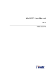
SOC8200 is an industrial evaluation kit designed and manufactured by Embest Info&Tech
Co.,LTD., SOC8200 is based on processor AM3517 of Texas Instrument (TI). Processor AM3715
is integrated with 600Mhz ARM Cortex-A8 Core which is dedicated using to Process industrial
signal. SOC8200 provides, 10/100Mbps Ethernet interface, S-VIDEO interface, Audio input and
output interfaces, USB device, USB HOST, SD card interface, series port, CF card, SPI interface,
I2C interface, JTAG interface, CAMERA interface, LCD interface, touch screen interface and
keyboard as well as HDMI (DVI-D) interface. This high performance and low power consumption
enable the device to support the following applications:
Industrial control, field communication, medical equipment, instrumentation, security
systems etc.
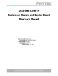
Fig1.1 SOC8200 Single Board Computer
1.2 System Module
AM3517 industrial applications processors
600MHz ARM Cortex-A8 Core
NEON SIMD Coprocessor
POWERVR SGX Graphics Accelerator
16KB I-Cache,16KB D-Cache,256KB L2-Cache,112KB ROM,64KB Share SRAM
Memory
256MB DDR2 SDRAM,32bit
256MB NAND Flash,8bit
4MB NOR Flash,16bit
Audio / Video Interface
Audio input interface
Stereo output
TFT LCD Video Output Interface(16bit true color signal)
Standard VGA output interface
Peripheral Interface
UART、USB Host、USB OTG、Ethernet、SD/MMC、CF、Versatile Expansion Interfaces
(McBSP、IIC、McSPI、TV-OUT)、PC104 Expansion Interface(GPMC Bus、MMC、
USB、McSPI、UART、Clock、HDQ)
Operating System
Linux
WinCE 6.0
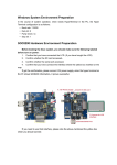
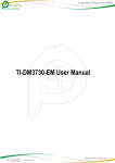
1.3 Architecture Diagram
The full system architecture diagram as follows:
Fig1.3 SOC8200 architecture diagram
SOC8200
32-bit microprocessor Base on AM3517
LCD, VGA, AV, S-video, serial port, Ethernet network, CAN, RS485, Audio In/Out, SD, CF,
USB
User Manual
2.1.2 Hardware Features
Processor
AM3517 industrial applications processors
NEON SIMD Coprocessor
600MHz ARM Cortex-A8 Core
POWERVR SGX Graphics Accelerator (AM3517 only)
16KB I-Cache, 16KB D-Cache, 256KB L2-Cache, 112KB ROM, 64KB Share SRAM
Memory
256MB DDR2 SDRAM, 32bit
256MB NAND Flash, 8bit
4MB NOR Flash, 16bit (driver has not provided at present)
Signals Routed to Pins
One 5-wire Debug serial port (RS232)
One 5-wire serial port (TTL)
Two USB 2.0 Host High-speed ports, 480Mbps
One USB 2.0 Device High-speed port, 480Mbps
One channel Audio input
Two channel Audio output
16-bit LCD output
10-bit Camera video input
One channel S-Video output
One channel AV output
One RS485 serial port
One channel CAN bus interface
10/100Mbps network interface
SD/MMC interface
Multi-functional expansion interface (McBSP, IIC, McSPI, TV-OUT)
PC104 expansion interface (GPMC Bus, MMC, USB, McSPI, UART1, Clock, HDQ)
JTAG interface
SOC8200
32-bit microprocessor Base on AM3517
LCD, VGA, AV, S-video, serial port, Ethernet network, CAN, RS485, Audio In/Out, SD, CF,
USB
User Manual
2.2.2 Network interface
SOC8200 is 10M/100M adaptive network interface
PIN
Description
1
GND
2
VCC_IO
3
TXN
4
TXP
5
GND
6
RXN
7
RXP
8
LED2/NINTSEL
9
LED1/REGOFF
10
GND
2.2.3 Camera Interface
PIN
Description
1
GND
2
CAM_D0
3
CAM_D1
4
CAM_D2
5
CAM_D3
6
CAM_D4
7
CAM_D5
8
CAM_D6
9
CAM_D7
10
CAM_D8
11
CAM_D9
12
GND
13
CAM_PCLK
14
GND
15
CAM_HS
16
CAM_VS
17
VCC_IO
18
IIC3_SDA
19
IIC3_SCL
20
GND
2.2.4 MMC Interface
PIN
Description
1
VCC_IO
2
MMC1_CLK
3
MMC1_CMD
4
MMC1_D0
5
MMC1_D1
6
MMC1_D2
7
MMC1_D3
8
MMC1_CD
9
MMC1_WP
10
GND
2.2.5 UART1 Interface
PIN
Description
1
N/A
2
N/A
3
R1IN
4
T2OUT
5
T1OUT
6
R2IN
7
N/A
8
N/A
9
GND
10
N/A
2.2.6 Analog IO Interface
PIN
Description
1
CH7
2
CH6
3
CH5
4
CH4
5
CH3
6
CH2
7
CH1
8
CH0
9
GND
10
VCC_IO
2.2.7 Digital IO Interface
PIN
Description
1
CH7
2
CH6
3
CH5
4
CH4
5
CH3
6
CH2
7
CH1
8
CH0
9
GND
10
VCC_IO
Table2.7 Digital IO Interface
2.2.8 TFT_LCD Interface
PIN
Description
1
GND
2
DSS_CLK
3
DSS_HS
4
DSS_VS
5
GND
6
N/A
7
DSS_D11
8
DSS_D12
9
DSS_D13
10
DSS_D14
11
DSS_D15
12
GND
13
DSS_D5
14
DSS_D6
15
DSS_D7
16
DSS_D8
17
DSS_D9
18
DSS_D10
19
GND
20
N/A
21
DSS_D0
22
DSS_D1
23
DSS_D2
24
DSS_D3
25
DSS_D4
26
GND
27
DSS_DEN
28
VCC_IO
29
VCC_IO
30
N/A
31
N/A
32
Y+
33
X-
34
Y-
35
X+
36
LCD_PEN
37
VCC_5V
38
LCD_ADJ
39
GND
40
N/A
2.2.9 PC104 Interface
2.2.9.1 PC104-64
PIN
Description
1
GND
2
N/A
3
VCC_5V
4
VCC_5V
5
VCC_IO
6
VCC_IO
7
GND
8
SYS_RST
9
POWER_RST
10
SYS_CLKOUT2
11
SYS_CLKOUT1
12
HDQ_SIO
13
SYS_32K
14
GND
15
IRQ
16
GPIO58
17
GPIO57
18
GPIO56
19
GPT11
20
GPT10
21
GPT9
22
IIC1_SDA
23
IIC1_SCL
24
GND
25
UART4_RX
26
RS485_TXEN
27
RS485_RXEN
28
UART4_TX
29
GND
30
MCBSP4_DX
31
MCBSP4_DR
32
MCBSP4_CLKX
33
MCBSP4_FSX
34
MCBSP_CLKS
35
GND
36
GPIO157
37
GPIO162
38
SPI4_CS0
39
SPI4_SOMI
40
SPI4_SIMO
41
SPI4_CLK
42
GND
43
SPI1_CS3
44
SPI1_CS2
45
SPI1_SOMI
46
SPI1_SIMO
47
SPI1_CLK
48
GND
49
MMC2_D7
50
MMC2_D6
51
MMC2_D5
52
MMC2_D4
53
MMC2_D3
54
MMC2_D2
55
MMC2_D1
56
MMC2_D0
57
MMC_CMD
58
MMC2_CLK
59
GND
60
U3_DP
61
U3_DM
62
U4_DM
63
U4_DP
64
GND
Table2.9 PC104-64 Interface
2.2.9.2 PC104-40
PIN
Description
1
GND
2
GPMC_NCS4
3
GPMC_NCS3
4
GPMC_NCS2
5
GPMC_A10
6
GPMC_A9
7
GPMC_A8
8
GPMC_A7
9
GPMC_A6
10
GPMC_A5
11
GPMC_A4
12
GPMC_A3
13
GPMC_A2
14
GPMC_A1
15
GPMC_NBE1
16
GPMC_WAIT3
17
SYS_RST
18
GPMC_CLE
19
GND
20
GPMC_ALE
21
GPMC_CLK
22
GPMC_WE
23
GPMC_OE
24
GPMC_D15
25
GPMC_D14
26
GPMC_D13
27
GPMC_D12
28
GPMC_D11
29
GPMC_D10
30
GPMC_D9
31
GPMC_D8
32
GPMC_D7
33
GPMC_D6
34
GPMC_D5
35
GPMC_D4
36
GPMC_D3
37
GPMC_D2
38
GPMC_D1
39
GPMC_D0
40
GND
2.2.10 Multifunctional Expansion Interface
PIN
Description
1
GND
2
TV_OUT1
3
GND
4
TV_OUT2
5
GND
6
VCC_IO
7
GND
8
MCBSP2_CLKX
9
MCBSP2_FSX
10
MCBSP2_DR
11
MCBSP2_DX
12
IIC2_SDA
13
IIC2_SCL
14
GND
15
SPI2_CLK
16
SPI2_SIMO
17
SPI2_SOMI
18
SPI2_CS0
19
SPI2_CS1
20
GND
2.2.11 Can/485 Interface
PIN
Description
1
CANH
2
CANH
3
CANL
4
CANL
5
CHGND
6
CHGND
7
RS485A
8
RS485B
9
RS485Z
10
RS485Y
11
MCBSP2_DX
12
IIC2_SDA
13
IIC2_SCL
14
GND
15
SPI2_CLK
16
SPI2_SIMO
17
SPI2_SOMI
18
SPI2_CS0
19
SPI2_CS1
20
GND
2.2.12 Power Interface
PIN
Description
1
VCC_5V
2
GND
2.2.13 UART (TTL) Interface
PIN
Description
1
VCC_IO
2
GND
3
UART2_CTS
4
UART2_RTS
5
UART2_TX
6
UART2_RX
2.2.14 JTAG Interface
PIN
Description
1
VCC
2
TMS
3
TDI
4
NTRST
5
TD0
6
RTCK
7
TCK
8
EMU0
9
EMU1
10
GND
COPYRIGHT
SOC8200 ,CAN8200, SD8200-X,CAN8200-X,AU8200,VGA8200,
USB8200-X,NET8200 ,ECOM-4,ECOM-8,E100 Module are trademarks of Embest Info&Tech
Co.,LTD.
AM3517 is trademark of TI Corporation.
Sourcery G++ Lite for ARM GNU/Linux is trademark of Codesourcery.
Microsoft, MS-DOS, Windows, Windows95, Windows98, Windows2000, Windows embedded
CE 6.0 are trademarks of Microsoft Corporation.
Rev
Date
Description
1.0
July 10,2010
Initial version
2.0
Dec 28,2010
Modified u-boot:
Added NORFLASH support,
Added TV/S-video output support
3.0
May 28,2011
Increased the support on wince6.0
Important Notice
No part of this document may be copied or reproduced in any form or by any means without the
prior written consent of Embest Info&Tech Co.,LTD.
1 System Overview
The document describes user how to develop with SOC8200, the detailes for hardware
specification, features, and software development.
1.1 Introduction
SOC8200 is an industrial evaluation kit designed and manufactured by Embest Info&Tech
Co.,LTD., SOC8200 is based on processor AM3517 of Texas Instrument (TI). Processor AM3715
is integrated with 600Mhz ARM Cortex-A8 Core which is dedicated using to Process industrial
signal. SOC8200 provides, 10/100Mbps Ethernet interface, S-VIDEO interface, Audio input and
output interfaces, USB device, USB HOST, SD card interface, series port, CF card, SPI interface,
I2C interface, JTAG interface, CAMERA interface, LCD interface, touch screen interface and
keyboard as well as HDMI (DVI-D) interface. This high performance and low power consumption
enable the device to support the following applications:
Industrial control, field communication, medical equipment, instrumentation, security
systems etc.
Digital output
Control independently
Table 3.1 BSP specifications
3.2 Linux System Quick Operation
Windows System Environment Preparation
In the course of system operation, when needs HyperTerminal in the PC, the Hyper Terminal
configuration is as follows:
Baud rate: 115200
Data bit: 8
Parity check: no
Stop bit: 1
SOC8200 Hardware Environment Preparation
Before booting the linux system, you should make sure the following labeled before turn on
power:
1. Confirm that you have connected the LCD. (If you have bought the LCD)
2. Confirm whether the SD card accessed;
3. Confirm whether the serial port accessed;
4. Confirm that you have connect the interface where the yellow box marked on the map.
If got the confirmation, please connect 12V power supply, when the hyper terminal on the
PC shows SOC8200 information, it proves successful.
If you need to use VGA interface, please note the above-mentioned the yellow box which you
should connect
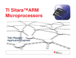
3.2.1 System boot methods
3.2.1.1 NAND Flash Boot
You can use the jumper cap to choose the boot
type, if connect the Place A, the board will boot
image from SD card, otherwise the board will boot
image from NAND Flash.
The nand flash already has the solidified code of
VGA display, user only need to connect the serial
port and set the hyper terminal configuration. User
can boot linux system from nand flash without
connect the jumper cap. If customers do not use
VGA, please refer to 【3.3.2 Update the image for
NAND Flash】.
3.2.1.2 SD card Boot
If you need to boot from the SD card, please refer to the following Display Options
3.2.2 Display Options
User need to replace the uImage to display LCD (4.3inch, 7inch) or VGA, concrete steps are as
follows:
1.Replace the SD card uImage file
Copy the image to the SD card and delete previous uImage. And rename the uImage_xx
as uImage on the SD card.
Warning:The XX’’LCD is the size of LCD you are using, it is included 4.3inch,
7inch, 10.4inch, VGA).
2. Enter U-boot Shell
40X
Texas Instruments X-Loader 1.45 (Mar 19 2010 - 16:09:58)
Starting X-loader on MMC
Reading boot sector
213544 Bytes Read from MMC
Starting OS Bootloader from MMC...
Starting OS Bootloader...
U-Boot 2009.11-svn ( 3 鏈?19 2010 - 16:14:31)
OMAP34xx/35xx-GP ES1.0, CPU-OPP2 L3-165MHz
AM3517EVM Board + LPDDR/NAND
I2C: ready
DRAM: 256 MB
NAND: 256 MiB
In:
serial
Out: serial
Err: serial
Die ID #796400000000000001543b2106011005
Net: davinci_emac_initialize
Ethernet PHY: GENERIC @ 0x00
DaVinci EMAC
Hit any key to stop autoboot: 3
When it starts to this here, the system will count down for 3 seconds. Then press any key, it will
enter the u-boot shell.
3. U-boot parameter settings
Input the following in bold type in the u-boot shell.
OMAP3517EVM # setenv bootargs console=ttyS2,115200n8 root=/dev/ram0 rw
rootfstype=ext2 initrd=0x81600000,40M
OMAP3517EVM # setenv bootcmd ‘mmc init\;fatload mmc 0 80300000
uImage\;fatload mmc 0 81600000 ramdisk.gz\;bootm 0x80300000’
OMAP3517EVM # saveenv
OMAP3517EVM # boot
3.2 3 Linux Function Test
3.2 3.1 Test on LED
Led1 on the SOC8200 has been used as power indicator light, led2 can be used.
The following (Linux systems) can complete the led2 test.
1. Light LED2.
[root@OMAP3EVM /]# echo -n 1 >/sys/class/leds/led/brightness
2. Extinguish LED2.
[root@OMAP3EVM /]# echo -n 0 >/sys/class/leds/led/brightness
3.2 3.2 Test on Touch Screen
After entering Linux system, execute the following commands to test:
1. Input the following commands to execute the touch screen calibration procedures:
[root@OMAP3EVM /]# ts_calibrate
Follow prompts on the screen, click the "+" icon five times to complete the calibration.
2. After the calibration is complete, enter the following commands for touch-screen test
[root@OMAP3EVM /]# ts_test
Follow prompts on the on screen prompts, choose to draw point, draw a line test.
3.2 3.3 Test on RTC
SOC8200 has a hardware clock, it is used to save and restore the system time, refer to the
following test methods:
1. Set the system time at 5:55 p.m. on the March 24, 2010:
[root@OMAP3EVM /]# date 032417552010
Wed Mar 24 17:55:00 UTC 2010
2. Write the system time into RTC:
[root@OMAP3EVM /]# hwclock -w
3. Read RTC:
[root@OMAP3EVM /]# hwclock
Wed Mar 24 17:55:06 2010 0.000000 seconds
The hardware clock RTC will be set to March 24 2010 and the system time is saved in the
hardware clock.
4. Reboot the system and input the following commands to restore the system time.
[root@OMAP3EVM /]# hwclock -s
[root@OMAP3EVM /]# date
Wed Mar 24 17:55:37 UTC 2010
3.2 3.4 Test on MMC/SD card
1. Insert the MMC/SD card and system displays the detection information:
[root@OMAP3EVM /]# mmc0: new MMC card at address 0001
mmcblk1: mmc0:0001 000000 122 MiB
mmcblk1: p1
2. Mount the MMC/SD card to directory of /mnt:
[root@OMAP3EVM /]# mount -t vfat /dev/mmcblk1p1 /mnt/
[root@OMAP3EVM /]# ls /mnt
MLO
u-boot.bin
ubi.img
flash-uboot.bin
uImage
x-load.bin.ift_for_NAND
3. Umount the SD card:
[root@OMAP3EVM /]# umount /mnt
3.2 3.5 Test on USB OTG
Use the SOC8200 as DEVICE,USB OTG as slave:
1. The user can connected to switch development board and the pc machine via USB mini B to
USB A cable after the system runs.
Install the Linux USB Ethernet/RNDIS Gadget driver according to the appendix
1.
2.After successful connection, PC will show a virtual network card as displayed in Fig 5.1:
Fig 5.1 virtual network card
3. Set the IP address of the virtual network card, for example:
Fig 5.2 IP Configuration
4. Set the IP network segment of SOC8200 board as the same as virtual network card:
[root@OMAP3EVM /]# ifconfig usb0 192.168.1.105
[root@OMAP3EVM /]# ifconfig
usb0
Link encap:Ethernet HWaddr CA:A3:26:97:50:A8
inet addr:192.168.1.105 Bcast:192.168.1.255 Mask:255.255.255.0
UP BROADCAST RUNNING MULTICAST MTU:1500 Metric:1
RX packets:145 errors:0 dropped:0 overruns:0 frame:0
TX packets:6 errors:0 dropped:0 overruns:0 carrier:0
collisions:0 txqueuelen:1000
RX bytes:14777 (14.4 KiB) TX bytes:796 (796.0 B)
5. Use the following command on the hyper terminal to test the SOC8200 board whether had
connected successfully.
[root@OMAP3EVM /]# ping 192.168.1.15
PING 192.168.1.15 (192.168.1.15): 56 data bytes
64 bytes from 192.168.1.15: seq=0 ttl=128 time=6.592 ms
64 bytes from 192.168.1.15: seq=1 ttl=128 time=0.549 ms
64 bytes from 192.168.1.15: seq=2 ttl=128 time=0.488 ms
64 bytes from 192.168.1.15: seq=3 ttl=128 time=0.458 ms
The address of OTG should not the same as net, user may change it.
3.2 3.6 Test on USB HOST
SOC8200 connect USB device:
1. Insert U-disk to the USB-HOST interface when SOC8200 board runs, and the system pops the
detection information automatically.
[root@OMAP3EVM /]# usb 1-1.1: new full speed USB device using ehci-omap and address 4
usb 1-1.1: not running at top speed; connect to a high speed hub
usb 1-1.1: New USB device found, idVendor=1976, idProduct=1307
usb 1-1.1: New USB device strings: Mfr=1, Product=2, SerialNumber=3
usb 1-1.1: Product: USB Reader
usb 1-1.1: Manufacturer: ChipsBnk
usb 1-1.1: SerialNumber: 110074973765
scsi1 : usb-storage 1-1.1:1.0
scsi 1:0:0:0: Direct-Access
ChipsBnk SD/MMCReader
4081 PQ: 0 ANSI: 2
sd 1:0:0:0: [sdb] 1990656 512-byte logical blocks: (1.01 GB/972 MiB)
sd 1:0:0:0: [sdb] Write Protect is off
sd 1:0:0:0: [sdb] Assuming drive cache: write through
sd 1:0:0:0: [sdb] Assuming drive cache: write through
sdb: sdb1
sd 1:0:0:0: [sdb] Assuming drive cache: write through
sd 1:0:0:0: [sdb] Attached SCSI removable disk
2. Mount the U-disk to directory of /mnt:
[root@OMAP3EVM /]# mount -t vfat /dev/sdb1/mnt/
3. Check the U-disk information.
[root@OMAP3EVM /]# ls /mnt/
MLO
ramdisk.gz
uImage-vga
emtest_auto
saMmapLoopback
ubi.img
fancuo.mp3
u-boot.bin
x-load.bin.ift_for_NAND
flash-uboot.bin
uImage
4. Umount the USB-host.
[root@OMAP3EVM /]# umount /mn
3.2 3.7 Test on network
The board has a 10/100M self-adapting network card DM9000; users can connect the board to the
LAN and enter the following commands for a test:
[root@OMAP3EVM /]# ifconfig eth0 192.192.192.201
eth0: attached PHY driver [Generic PHY] (mii_bus:phy_addr=ffffffff:00, id=7c0f1)
[root@OMAP3EVM /]# PHY: ffffffff:00 - Link is Up - 100/Full
[root@OMAP3EVM /]# ping 192.192.192.90
PING 192.192.192.90 (192.192.192.90): 56 data bytes
64 bytes from 192.192.192.90: seq=0 ttl=128 time=5.005 ms
64 bytes from 192.192.192.90: seq=1 ttl=128 time=0.396 ms
64 bytes from 192.192.192.90: seq=2 ttl=128 time=0.305 ms
64 bytes from 192.192.192.90: seq=3 ttl=128 time=0.305 ms
64 bytes from 192.192.192.90: seq=4 ttl=128 time=0.305 ms
Warning: user may change IP address, press ctrl+c to quit.
3.2 3.8 Test on camera
Connect camera module (Option) and CCD camera well, and execute following commands to test
after entering the system.
[root@OMAP3EVM /mnt]# saMmapLoopback
Capture: Opened Channel
Capture: Current Input: Composite
Capture: Input changed to: Composite
Capture: Current standard: NTSCvpfe-capture vpfe-capture: width = 720, height = 480, bpp = 2
vpfe-capture vpfe-capture: adjusted width = 720, height = 480, bpp = 2, bytesperline = 1440,
sizeimage = 691200
Capture: Number of requested buffers = 2
Capture: Init done successfully
Display: Opened Channel
Display: Capable of streaming
Display: Number of requested buffers = 3
Display: Init done succetvp514x 3-005d: tvp5146 (Version - 0x03) found at 0xba (OMAP I2C
adapter)
ssfully
Display: Stream on...
Capture: Stream on...
LCD shows the image collected by the camera. ( press ctrl+c to quit the test )
3.2 3.9 Test on CAN
If the user want to connect the CAN device, please use the CAN8200。
The steps for the CAN connection:
1. The steps for setting:
Set the CAN baud rate as 125 k/bits, and enable the CAN devices.
[root@OMAP3EVM bin]# /usr/bin/ip link set can0 type can bitrate 125000 triple-sampling on
[root@OMAP3EVM bin]# /usr/bin/ip link set can0 up
ti_hecc ti_hecc.1: setting CANBTC=0xc00a8
2. Send the data:
Input the following commands for send data as " 1122334455667788".
[root@OMAP3EVM bin]# /usr/bin/cansend can0 111#1122334455667788
3. Receive the data:
Input the following commands for receive the data:
[root@OMAP3EVM bin]# /usr/bin/candump can0
Receive the data that your send:
can0
80 [8] 01 02 03 04 05 06 07 08
can0
80 [8] 01 02 03 04 05 06 07 08
3.2 3.10 Test on ADC
The user can input the analog voltage for PIN1~8 (/dev/adc7 ~ /dev/adc0) on connector J5, the
input analog voltage rate is 0v ~ 3.3v, for the 12 bit AD conversion, the system will display the
digit voltage.
Input the following commands to check the PIN1 analog voltage:
[root@OMAP3EVM /]# adc_test -d /dev/adc7
The channel: /dev/adc0 0x0fff data: 3.2990 V
The channel: /dev/adc0 0x0fff data: 3.2990 V
The channel: /dev/adc0 0x0fff data: 3.2990 V
If it is the pin2, the commands is "adc_test -d /dev/adc6". When the pins is empty,
the digit voltage is 2.2V.
3.2 3.11 Test on SD card
1. Connect to the SD card to the SOC8200 board, if the appear the following information on the
debug port, the SD card had detected.
mmc0: new high speed SD card at address 0001
mmcblk0: mmc0:0001 APPSD 1.85 GiB
mmcblk0: p1
2. Input the following commands to mount the SD card.
[root@OMAP3EVM /]# mount -t vfat /dev/mmcblk0p1 /mnt
[root@OMAP3EVM /]# ls /mnt
Windows Embedded CE 6.0 R2
NCP
3. Umount the SD card.
[root@OMAP3EVM /]# umount /mnt
linux-2.6.24
3.2 3.12 Test on buzzer
1. Enable the buzzer:
[root@OMAP3EVM /]# echo 1 > /sys/class/misc/beep/val
2. Off the buzzer:
[root@OMAP3EVM /]# echo 0 > /sys/class/misc/beep/val
3.2 3.13 Test on AUDIO
The board has audio input and output interface, and we have alsa-utils audio test tools in the
filesystem, users can enter the following commands for a test:
1. Recording Test:
[root@OMAP3EVM /]# arecord -t wav -c 2 -r 44100 -f S16_LE -v k
Recording WAVE 'k' : Signed 16 bit Little Endian, Rate 44100 Hz, Stereo
Plug PCM: Hardware PCM card 0 'omap3evm' device 0 subdevice 0
Its setup is:
stream
: CAPTURE
access
: RW_INTERLEAVED
format
: S16_LE
subformat
: STD
channels
:2
rate
: 44100
exact rate : 44100 (44100/1)
msbits
: 16
buffer_size : 22052
period_size : 5513
period_time : 125011
tstamp_mode : NONE
period_step : 1
avail_min
: 5513
period_event : 0
start_threshold : 1
stop_threshold : 22052
silence_threshold: 0
silence_size : 0
boundary
: 1445199872
appl_ptr
:0
hw_ptr
:0
Press CONTROL+C to quit the test.
2. Playback Testing:
[root@OMAP3EVM /]# aplay -t wav -c 2 -r 44100 -f S16_LE -v k
Playing WAVE 'k' : Signed 16 bit Little Endian, Rate 44100 Hz, Stereo
Plug PCM: Hardware PCM card 0 'omap3evm' device 0 subdevice 0
Its setup is:
stream
: PLAYBACK
access
: RW_INTERLEAVED
format
: S16_LE
subformat
: STD
channels
:2
rate
: 44100
exact rate : 44100 (44100/1)
msbits
: 16
buffer_size : 22052
period_size : 5513
period_time : 125011
tstamp_mode : NONE
period_step : 1
avail_min
: 5513
period_event : 0
start_threshold : 22052
stop_threshold : 22052
silence_threshold: 0
silence_size : 0
boundary
: 1445199872
appl_ptr
:0
hw_ptr
:0
3.2 3.14 Test on full-function serial port
SOC8200-M has 3 serial port:
Interface
Type
Encapsulati
on
Device nodes
dBm
Extended
serial port
0
Full-function
serial port
Interface for
DB9
/dev/ttySCMA0
RS232
Extended
serial port
1
Full-function
serial port
Interface for
IDC
/dev/ttySCMA1
TTL
Debug port
Three-wire
serial port
Interface for
IDC
/dev/ttyS2
RS232
Test program
3 line
com_norts
9 line
com_rts
3 line
com_norts
9 line
com_rts
System Integration
1. Test preparation
As the following Fig, the red pane is extended serial port 0, the test is subject to extended serial
port 0.
The step for the connection:
The serial setting for the PC:
Baud rate: 115200
Data bit: 8
Stop bit: 1
Parity bit: None
Control flow: Hardware
DTR: On
RTS: On
2. Test for communication:
1) Connect the extended serial port 0 and PC via 3-wire mode
Input the following commands, the SOC8200 board will send data “1234567890 " to the PC. If the
PC has send the data to SOC8200 board, the board will receive the data too.
[root@OMAP3EVM ]# com_norts -d /dev/ttySCMA0
SEND: 1234567890
RECV: www.armkits.com
RECV: www.armkits.com
SEND: 1234567890
RECV: www.armkits.com
RECV: www.armkits.com
SEND: 1234567890
2)Connect the extended serial port 0 and PC via 9-wire mode:
Input the following commands, the SOC8200 board will send data " 1234567890 " to the PC. If
the PC has send the data to SOC8200 board, the board will receive the data too.
[root@OMAP3EVM ]# com_rts -d /dev/ttySCMA0
SEND: 1234567890
RECV: SOC8200
RECV: SOC8200
SEND: 1234567890
RECV: SOC8200
RECV: SOC8200
SEND: 1234567890
RECV: SOC8200
RECV: SOC8200
SEND: 1234567890
For the test program com_rts and com_norts, the user can add the " -s " to change
the send content.
3.2 3.15 Test on digit output
The pins 1 to 8 on the connector J6 can output the digit voltage 0V and 3.3V, the default the
output 3.3v when reset the board.
1. Device introduce:
[root@OMAP3EVM /]# cd /sys/class/misc/digital/
[root@OMAP3EVM digital]# ls
dev
out2
out4
out6
out8
power
uevent
out1
out3
out5
out7
outall
subsystem
As the above, the out1 has corresponding the pin1, the outall has corresponding the pins for 1 to 8.
2. Set the only pin voltage:
[root@OMAP3EVM digital]# echo 1 > out3
[root@OMAP3EVM digital]# cat out3
1
3. Set the all pins voltage:
[root@OMAP3EVM digital]# echo aa > outall
[root@OMAP3EVM digital]# cat outall
aa
3.3 Linux Image Update
SOC8200 supports MMC/SD boot or NAND boot; different start-up modes will have different
method for updating the image. We will introduce the update of image under different start-up
modes.
3.3.1 Update the image for SD card
3.3.1.1 Prepare
1 The formatting of MMC/SD card
Recommend to use HP USB Disk Storage Format Tool:
The software is download from:
http://www.embedinfo.com/english/download/SP27213.exe.
1) Insert MMC/SD card into the card reader in PC
2) Open the HP USB Disk Storage Format Tool, the following tips will show:
Fig 3.4 Formatting tool of HP USB Disk
3) Select “FAT32”
4) Click “Start”
5) When formatting is completed, click “OK”
This tool will delete all partition on the SD/MMC card.
2. Preparing the SD card file
1)Copy the all the file on the directory of disk/linux/image.
2) Depending on your display device LCD (4.3inch,7inch) or VGA, rename uImage_xx as uImage
The foregoing “XX” mean your LCD inch, it is included 4.3inch, 7inch and VGA.
3.3.1.2 Update the image
1. Enter to the u-boot command
Insert the SD card to the SOC8200 board, and make sure you had connect the jumper cap on the
J24 (the “A” on the following Fig)
Despite update the image for SD card or NAND Flash, it must start the image for
SD card.
The users have to enter to the u-boot command line mode first:
40X
Texas Instruments X-Loader 1.45 (Mar 19 2010 - 16:09:58)
Starting X-loader on MMC
Reading boot sector
213544 Bytes Read from MMC
Starting OS Bootloader from MMC...
Starting OS Bootloader...
U-Boot 2009.11-svn ( 3 鏈?19 2010 - 16:14:31)
OMAP34xx/35xx-GP ES1.0, CPU-OPP2 L3-165MHz
AM3517EVM Board + LPDDR/NAND
I2C: ready
DRAM: 256 MB
NAND: 256 MiB
In:
serial
Out: serial
Err: serial
Die ID #796400000000000001543b2106011005
Net: davinci_emac_initialize
Ethernet PHY: GENERIC @ 0x00
DaVinci EMAC
Hit any key to stop autoboot: 3
When it starts to this here, the system will count down for 3 seconds. Then press any key, it will
enter the u-boot command line mode.
2. Set U-boot parameter
Input the following in bold type in the u-boot .
Set the boot baud rate, boot from ram0 (SD card) and select the file system as ext2:
OMAP3517EVM # setenv bootargs console=ttyS2, 115200n8 root=/dev/ram0 rw
rootfstype=ext2 initrd=0x81600000, 40M
Set the image (uImage, ramdisk.gz) boot.from SD card:
OMAP3517EVM # setenv bootcmd ‘mmc init\; fatload mmc 0 80300000 uImage\; fatload
mmc 0 81600000 ramdisk.gz\; bootm 0x80300000’
Save the env and boot kernel:
OMAP3517EVM # saveenv
OMAP3517EVM # boot
3.3.2 Update the image for NAND Flash
3.3.2.1 Prepare
Use HP USB Disk Storage Format Tool 2.0.6 software to format the SD card, copy all files from
the CD linux / image / to the SD card and depending on your display device LCD (4.3,7) or VGA,
rename uImage_xx To uImage
Notice:the foregoing “XX” mean your LCD inch, it is included 4.3inch, 7inch
and VGA.
3.3.2.2 Update system image
MLO
WritetoNAND
NANDNAND
u-boot.bin
Boot
from
SD
uImage
ramdisk.gz
x-load.bin.ift_for_NAND
flash-uboot.bin
uImage
ubi.img
Nand Flash update principle
Update the image for NAND Flash must input the commands in u-boot shell, please refer the
following steps:
1、The update of x-loader boot image
Input the following commands in the u-boot shell:
Update image for SD card:
mmc init
fatload mmc 0 80000000 x-load.bin.ift_for_NAND
nand erase 0 80000
nandecc hw
nand write.i 80000000 0 $filesize
2. The update of u-boot boot image
Input the following commands in the u-boot shell:
Boot
from
NAND
Update image for SD card:
mmc init
fatload mmc 0 80000000 flash-uboot.bin
nand erase 80000 160000
nandecc sw
nand write.i 80000000 80000 $filesize
3. The update of kernel boot image
Input the following commands in the u-boot shell:
Update image for SD card:
mmc init
fatload mmc 0 80000000 uImage
nand erase 280000 300000
nandecc sw
nand write.i 80000000 280000 $filesize
4、The update of filesystem boot image
Input the following commands in the u-boot shell:
Update image for SD card:
mmc init
fatload mmc 0 81000000 ubi.img
nand erase 680000
nandecc sw
nand write.i 81000000 680000 $filesize
5、Modify the u-boot environment parameter
Input the following commands in the u-boot shell:
OMAP3517EVM # setenv bootargs console=ttyS2, 115200n8 ubi.mtd=4 root=ubi0: rootfs
rootfstype=ubifs
OMAP3517EVM # setenv bootcmd nand read.i 80300000 280000 300000\; bootm 80300000
OMAP3517EVM # saveenv
3.4 Linux System Deveplopment
This section will introduce how to establish a Linux system development platform run on
SOC8200 hardware platform with the use of SOC8200 BSP. Details to be provided contain the
formation of cross compilation environment, the generation of system image and demonstrate how
to customize the system.
For the SD card, After formatting and dividing into FAT and EXT3 under ubuntu system, the FAT
needs reformatting under windows system, otherwise, start-up with SD card can be realized.
The Linux said thereof is ubuntu 7.10 which will be referred as ubuntu.
3.4.1.1
Install the cross compilation environment
User must well form an arm Linux cross compilation environment before developing the
SOC8200. We will take ubuntu operating system as the example to introduct the formation of
cross compilation environment. The operation in Linux is similar with that in ubuntu system.
Insert the CD, ubuntu will put the CD under /media/cdrom directory, and the cross compilation
tool will be put under /media/cdrom/linux/tools directory.
Users can execute the following commands to start up the installation of cross compilation tool:
cd /media/cdrom/linux/tools
tar xvjf arm-2009q1-203-arm-none-linux-gnueabi-i686-pc-linux-gnu.tar.bz2 -C
/home/embest
The manual takes /home/embest as default installation directory. Users may
change the path.
3.4.1.2 The installation of other tools
Other tools included in linux/tools directory of CD may be used for source code. Users can
execute the following commands for installation:
mkdir /home/embest/tools
cp /media/cdrom/linux/tools/mkimage /home/embest/tools
cp /media/cdrom/linux/tools/signGP /home/embest/tools
cp /media/cdrom/linux/tools/mkfs.ubifs /home/embest/tools
cp /media/cdrom/linux/tools/ubinize /home/embest/tools
cp /media/cdrom/linux/tools/ ubinize.cfg /home/embest/tools
3.4.1.3 Adding environment variable
After installation of the above tools, those tools can be added into environment variable with the
following commands:
export PATH=/home/embest/arm-2009q1/bin:/home/embest/tools:$PATH
Users can put it into the barsrc file, and the adding of environment variable can
be finished as the system starts.
3.4.2 system complie
3.4.2.1 Preparation
The source code of each part of the system is under the linux/source of CD. Users can copy it to
the system and unzip it before developing. For example:
mkdir /home/embest/work
cd /home/embest/work
tar xvf /media/cdrom/linux/source/ x-loader-03.00.00.04.tar.bz2
tar xvf /media/cdrom/linux/source/ u-boot-03.00.00.04.tar.bz2
tar xvf /media/cdrom/linux/source/ linux-03.00.00.04.tar.bz2
sudo tar xvf /media/cdrom/linux/source/rootfs.tar.bz2
When the above steps are finished, the current directory will generate linux-2.6.22-omap,
u-boot-1.3.3 and x-load-1.41 these three directories.
3.4.2.2 x-loader image generated
DevKit8200 supports MMC/SD boot or NAND boot. The burned x-loader image files are
different with the different boot modes, and the corresponding methods for mapping will differ
too.
We will introduce the generation of x-loader image file under different boot modes.
1. To generate x-loader image file MLO used for SD card start-up
When the above steps are finished, the current directory will generate the file MLO we need.
cd x-load-03.00.00.04
make distclean
make am3517evm_config
make
signGP x-load.bin
mv x-load.bin.ift MLO
2. To generate the x-load.bin.ift_for_NAND start-up
1)To alter the file x-loader-1.4.1/include/configs/am3517evm.h and annotate the following:
vi x-loader-03.00.00.04/include/configs/am3517evm.h
//#define CONFIG_MMC
1
(2)Cross compilation
cd x-load-1.41
make distclean
make am3517evm _config
make
signGP x-load.bin
mv x-load.bin.ift x-load.bin.ift_for_NAND
When the above steps are finished, the current directory will generate the file
x-load.bin.ift_for_NAND we need.
3.4.2.3 u-boot image generated
cd u-boot-03.00.00.04/
make distclean
make am3517_evm_config
make
When the above steps are finished, the current directory will generate the file u-boot.bin we need.
3.4.2.4 kernel image generated
User may change linux-03.00.00.04/drivers/video/omap2/displays/
panel-sharp-lq043t1dg01.c, the default display is VGA.
//#define LCD_43inch
1
//#define LCD_7inch 1
#define VGA
1
Compilation
cd linux-03.00.00.04/
make distclean
cp arch/arm/configs/omap3_soc8200_defconfig .config
make
make uImage
When the above steps are finished, the arch/arm/boot directory will generate the file uImage we
need.
3.4.2.5 ubifs image generated
cd /home/embest/work
sudo /home/embest/tools/mkfs.ubifs -r rootfs -m 2048 -e 129024 -c 812 -o ubifs.img
sudo /home/embest/tools/ubinize -o ubi.img -m 2048 -p 128KiB -s 512
/home/embest/tools/ubinize.cfg
When the above steps are finished, the current directory will generate the file ubi.img we need.
3.4.3 System Customization
Actually, Linux kernel has many options for configuring the kernel. According to the default
configuration, users can add or delete some configuration to suit different need. The following
example illustrates the general process of system customization.
3.4.3.1 Alteration of kernel configuration
Kernel source code provides the default configuration file:
arch/arm/configs/omap3_soc8200_defconfig
Users can customize the system on the basis of this file
cd linux-03.00.00.04/
cp arch/arm/configs/omap3_soc8200_defconfig .config
make menuconfig
The example that we use usb gadget to simulate usb mass storage device will be taken to introduce
the system customization:
1. Select Device drivers
Symbol: USB_FILE_STORAGE [=m]
Prompt: File-backed Storage Gadget
Defined at drivers/usb/gadget/Kconfig:713
Depends on: <choice> && BLOCK [=y]
Location:
-> Device Drivers
-> USB support (USB_SUPPORT [=y])
-> USB Gadget Support (USB_GADGET [=y])
-> USB Gadget Drivers (<choice> [=m])
2. Select the following Fig option (File-backed Storage Gadget).
3. Select the “exit” until display the following Fig.
Select the ”Yes”.
3.4.3.2 Compilation
Save the configuration and execute the following command to recompile the kernel:
make
make uImage
After the above steps are finished, arch/arm/boot directory will generate a new kernel image
uImage; drivers/usb/gadget directory will generate a new module file g_file_storage.ko.
3.4.3.3 Test
Update kernel image file ulmage in SD card, copy file g_file_storage.ko to the SD card and reboot
the system from SD. Execute the following commands to stimulate the SOC8200 into usb mass
storage device for PC’s visit:
root@DevKit8000:~# mount –t vfat /dev/mmcblk0p1 /mnt
root@DevKit8000:~# cd /mnt
root@DevKit8000:/mnt# insmod g_file_storage.ko file=/dev/mmcblk0p1 stall=0 removable=1
g_file_storage gadget: File-backed Storage Gadget, version: 7 August 2007
g_file_storage gadget: Number of LUNs=1
g_file_storage gadget-lun0: ro=0, file: /dev/mmcblk0p1
musb_hdrc musb_hdrc: MUSB HDRC host driver
musb_hdrc musb_hdrc: new USB bus registered, assigned bus number 2
usb usb2: configuration #1 chosen from 1 choice
hub 2-0:1.0: USB hub found
hub 2-0:1.0: 1 port detected
Use the USB line (USB mini B to USB A) to connect the development board and PC, PC will give
a hint that usb mass storage device is found; a new mobile hard disk is found and users can
perform operation for it.
Please make sure that the kernel image has been updated, otherwise, module
g_file_storage.ko will fail to load and the similar tips will show:
insmod: cannot insert '/media/mmcblk0p1/g_file_storage.ko': Device or resource
busy
3.4.4 The Development Of Application
This section will introduce how to conduct the development of application on the SOC8200
hardware platform, including the formation of SOC8200 software environment. Examples will be
taken to show the general process of the development of SOC8200 application.
3.4.4.1 LED application development
1.Coding
Led_acc.c source code, The led lamps in the development board will flash.
#include <stdio.h>
#include <unistd.h>
#include <sys/types.h>
#include <sys/ipc.h>
#include <sys/ioctl.h>
#include <fcntl.h>
#define LED "/sys/class/leds/led/brightness"
int main(int argc, char *argv[])
{
int f_led;
unsigned char i = 0;
unsigned char dat;
if((f_led = open(LED, O_RDWR)) < 0){
printf("error in open %s",LED);
return -1;
}
for(;;){
i++;
//dat = i&0x1 ? '1':'0';
//dat = (i&0x2)>>1 ? '1':'0';
dat = (i&0x4)>>2 ? '1':'0';
write(f_led, &dat, sizeof(dat));
usleep(300000);
}
}
2. Cross compilation
arm-none-linux-gnueabi-gcc led_acc.c -o led_acc
3. Download and run
Resources can be put into the SOC8200 board system in the way of SD card or U flash card or
download. Then enter the directory that file led_acc exists, and input the following commands and
enter, then the led_acc will run in the background.
./led_acc &
4 WinCE System
4.1 WinCE system Overview
SOC8200 software system includes: pre-compiled images and applications and their
corresponding static library, dynamic link library, header file and source code; cross compilation
tools, auxiliary tools for development. Images, applications, Cross compilation tools used for
generating image and application can be downloaded from Microsoft. Image, application, source
code and auxiliary tools of SOC8200 can be found in the release CD or SD card of SOC8200.
The SD card of SOC8200 has the following software:
X-Loader image(MLO)
Ethernet Bootloader(EBOOT)image(EBOOTSD.nb0)
Windows Embedded CE 6.0 sample OS image(NK.bin)
The CD of SOC8200 includes:
Windows Embedded CE 6.0 SOC8200 Board Support Package(BSP)source code for TI
OMAP35X
Windows Embedded CE 6.0 project for SOC8200 BSP
SOC8200 application development example(source code)
Auxiliary development tools
This section mainly introduces and SOC8200 software system and covers description of
pre-compiled images and BSP and test kit, some functions and features of various images and
applications in the CD.
4.1.1 Pre-compiled image
The pre-compiled images include boot image X-Loader and EBOOT and sample OS image.
X-Loader is a first level bootloader. After the start-up of system, the ROM inside the CPU will
copy the x-loader to internal RAM and perform work. Its main function is to initialize the CPU,
and copy EBOOT to DDR memory and execute EBOOT. EBOOT is a second level bootloader, by
default, it will copy system image to DDR memory and hand the control right to the operating
system. EBOOT also can provide related functions to manage the basic hardware and set the
shared data in operating system.
Windows Embedded CE 6.0 provide multimedia module, industry module, PDA module, mobile
module and micro kernel module, user can choose the module that they want.Taking Mobile
Handheld as an example, the pre-compiled images support the following:
Image
Feature
X-Loader
To boot EBOOT
To boot the operating system from the network
(network card or RNDIS)
EBOOT
To boot the operating system with SD card
To boot the operating system from the NAND
Flash
Windows Explorer
Console Window
CAB File Installer/Uninstaller
Internet Explorer 6.0
Demonstrated operating system
ActiveSync
Power Management (Full)
.NET Compact Framework 3.5
Hive-based Registry
RAM and ROM File System
Device Drivers
4.1.2 Board Support Package (BSP)
SOC8200 BSP is used to customize the boot image and Windows Embedded CE 6.0 OS image
run on SOC8200 hardware platform. It supports the following:
Module
Feature
NAND
X-Loader module
ONENAND
SD
NAND
EBOOT module
ONENAND
SD
ILT
OAL module
REBOOT
Watchdog
RTC
KITL module
RNDIS KITL
NLED driver
GPIO/I2C/SPI/MCBSP driver
Series port driver
Driver module
6X6 keyboard driver
Audio driver
NAND(K9F1G08)driver
Display driver(LCD/DVI. S end/TV)/ TOUCH
driver
SD/MMC/SDIO driver
DM9000 network card driver
USB OTG driver
USB EHCI driver
VRFB driver
DSPLINKK/CMEMK driver
GPIO keyboard driver
PWM(TPS65930)driver
ADC(TPS65930)driver
ONENAND driver
SMSC911X network card driver
CAN driver
Buzzer drive
Backlight driver
Power management module
Battery driver
Sleep / wake-up button driver
Expansion of power management
Flash Plug-in and Flash player
Application module
MP3/MPEG4/H264 DSP Hardware decoder
BSPINFO(control panel)
CETK
4.2 WinCE system quick start
4.2.1 system boot
When you boot the board and operate the system, you may use the terminal,
Please open PC Window Hyper terminal software and set the following:
Baud rate: 115200
Data bit: 8
Parity check: no
Stop bit: 1
Flow control: no
4.2.1.1 Boot from Nand Flash
NAND Flash system in the renewal of the reference image methods, please refer to 【 4.4.2
Update the image for NAND Flash 】.
4.2.1.2 Boot from SD card
Copy image files MLO、EBOOTSD.nb0、NK.bin From CD:\WinCE\image\
VGA_1024x768(lcd_800x480 or lcd_480x272)\SD directory to SD card.
If users need to switch to SD card, need to start in SOC8200 J24 connected to the motherboard
jump line on cap, electric start, the system immediately instead from MMC/SD start.
the method to update the image from the SD card will be show in 【4.4.1 Update
the image for SD card】
4.3 WINCE System Development
4.3.1 Development environment building
4.3.1.1 Install the cross compilation environment
Based on the development of the SOC8200 involves two aspects: the bottom SOC8200 is based
on the hardware configuration and the development of Windows CE 6.0 operating system;
Embedded security The upper is developed on the basis of the operating system application. Two
levels of Windows CE 6.0 development are Embedded security must be based on Visual Studio
2005 (VS2005) integrated development environment.
Developing applications need installing software and updating:
Visual Studio 2005
Visual Studio 2005 SP1
Visual Studio 2005 SP1 Update for Vista (if applicable)
ActiveSync 4.5
The development of Windows Embedded CE 6.0 requires sequential installation of software and
updating:
Visual Studio 2005
Visual Studio 2005 SP1
Visual Studio 2005 SP1 Update for Vista (if applicable)
Windows Embedded CE 6.0 Platform Builder
Windows Embedded CE 6.0 SP1
Windows Embedded CE 6.0 R2
Windows Embedded CE 6.0 Product Update Rollup 12/31/2008
If there is an old CE development environment in the system, the use of Windows
Embedded CE 6.0 development platform may be influenced. Uninstalling the old
one and then installing the new one is recommended.
Please refer to appendix part, determine the of all kinds of resources get streams of
information;
All of these software or component system since there are dependent relationship
with Suggestions listed in strict accordance with the installation, and installed in
order default path.
4.3.2 system complie
If the sample Windows Embedded CE 6.0 OS image in the CD of SOC8200 satisfies your
applications, you just need to add it into your application and get the authorization of Microsoft
Corporation. Otherwise, you will need to re-customize the system and rebuild the image. This
section describes how to use SOC8200 Board Support Package (BSP) to create the Windows
Embedded CE 6.0 system image run on SOC8200 hardware platform.
4.3.2.1 Preparation
Embest Info&Tech Co.,LTD., has completed in SOC8200 hardware platform driver and the related
resources integration, so the user is in use in SOC8200 customize Windows CE 6.0 system,
Embedded security before has need of the following preparation:
Decompress [SOC8200\WinCE\BSP\AM35x_BSP.rar] to obtain AM35x_BSP directory.
Decompress [SOC8200\WinCE\BSP\COMMON_TI_V1.rar] to obtain COMMON_TI_V1
directory.
Decompress [SOC8200\WinCE\BSP\AM35x_OSDesign.rar] to obtain AM35x_OSDesign
directory.
Copy Decompress directory [SOC8200\WinCE\BSP\AM35x_BSP ] to
[C:\WINCE600\PLATFORM] directory。
Copy Decompress directory [SOC8200\WinCE\BSP\AM35x_OSDesign ] to
[C:\WINCE600\OSDesigns] directory。
Copy Decompress directory [SOC8200\WinCE\BSP\COMMON_TI_V1 ] to
[C:\WINCE600\PLATFORM\COMMON\SRC\SOC\] directory。
C:\WINCE600\OSDesigns OSDesigns need to establish the folder.
For the 4.3” LCD
Modify C:\wince600\platform\am35x_bsp\src\bsp_common\display\Lcd_cfg.h
//------------------------------------------//#define lcd_7inch 1
#define lcd_43inch 1
//#define lcd_vga_1024x768 1
//-------------------------------------------For the 7” LCD
Modify C:\wince600\platform\am35x_bsp\src\bsp_common\display\Lcd_cfg.h
//------------------------------------------#define lcd_7inch 1
//#define lcd_43inch 1
//#define lcd_vga_1024x768 1
//-------------------------------------------For the VGA
Modify C:\wince600\platform\am35x_bsp\src\bsp_common\display\Lcd_cfg.h
//------------------------------------------//#define lcd_7inch 1
//#define lcd_43inch 1
#define lcd_vga_1024x768 1
//-------------------------------------------If user needs to use SOC8200 BS to develop Windows Embedded CE 6.0
operating system, the construction of Windows Embedded CE 6.0 development
platform is required.
This manual takes the default installation path for Windows Embedded CE 6.0
software, i.e. its default path is [C:\WINCE600].
4.3.2.2 System Complie
1.
2.
3.
4.
5.
Open the file SOC8200 .sln[C:\WINCE600\OSDesigns\SOC8200 ] or take the following
steps to create a new project:
Open Visual Studio 2005.
Select the menu: File [New->Project].
Select template type of Platform Builder for CE 6.0
Select a file name and open Windows Embedded CE 6.0 OS Design Wizard
Set the Embest SOC8200 BSP into the BSP list.
Continue to finish the Wizard.
Select submenu [Build-> Global Build Settings]
Copy Files to Release Directory After Build
Make Run-Time Image After build
If KITL is needed, set Enable Kernel Debugger and Enable KITL into Build Options page
[Project-> Properties].
Select [Build-> Build Solution] to build BSP. These operations cover the whole compilation
including sysgen operating system’s components. After a entire compilation process is
completed, the build commands under Solution Explorer window can be used to save the
build time.
Images including NK.bin, EBOOTSD.nb0 and MLO and so on will be generate; Copy the
files MLO, EBOOTSD.nb0 and NK.bin under
[C:\WINCE600\OSDesigns\SOC8200\SOC8200\RelDir\SOC8200_ARMV4I_Release] to
the SD card. Insert the SD card into the device and boot the device for a test.
In the system in the process of compiling, the user should be in the "solution"
choice "in the box with AM35x_BSP_ARMV4I_Release".
4.3.2.3 System Customization
Windows Embedded CE 6.0 consists of a number of independent modules. Each module provides
specific functions, of which some modules can be divided into several components. Each
component has specific feature, making OEM/ODM customize a stable and efficient version
according to specific application.
Taking Mobile Handheld as a template, sample SOC8200 OS image adds features of components
including:
Component
Path
CAB File Installer/Uninstaller
Core OS->CEBASE->Application – End User
.NET Compact Framework 3.5
Core
OS->CEBASE->Applications
and
Services
Development->.NET
Compact
Framework 3.5
OS Dependencies
Framework 3.5
Core
OS->CEBASE->Applications
and
Services
Development->.NET
Compact
Framework 3.5-> OS Dependencies for .NET
Compact Framework 3.5
for
.NET
Compact
Point-to-Point Protocol over Ethernet (PPPoE)
Core OS->CEBASE->Communication Services
and Networking->Networking – Wide Area
Network (WAN)
USB Function Driver
Core OS->CEBASE->Core OS Services->USB
Host Support
USB Host Support
Core OS->CEBASE->Core OS Services->USB
Host Support
USB Human Input Device (HID) Class Driver
Core OS->CEBASE->Core OS Services->USB
Host Support
USB HID Keyboard and Mouse
Core OS->CEBASE->Core OS Services->USB
Host Support-> USB Human Input Device
(HID) Class Driver
USB Storage Class Driver
Core OS->CEBASE->Core OS Services->USB
Host Support
RAM and ROM File System
Core OS->CEBASE->File Systems and Data
Store->File System – Internal (Choose 1)
Hive-based Registry
Core OS->CEBASE->File Systems and Data
Store->Registry Storage – Internal (Choose 1)
exFAT File System
Core OS->CEBASE->File Systems and Data
Store->Storage Manager
FAT File System
Core OS->CEBASE->File Systems and Data
Store->Storage Manager
Storage Manager Control Panel Applet
Core OS->CEBASE->File Systems and Data
Store->Storage Manager
Transaction-Safe FAT File System (TFAT)
Core OS->CEBASE->File Systems and Data
Store->Storage Manager
Video/Image Compression Manager
Core
OS->CEBASE->Graphics
and
Multimedia
Technologies->Media->Video
Codecs and Renderers
Console Window
Core
OS->CEBASE->Shell
and
Interface->Shell->Command Shell
SD Memory
Device Drivers->SDIO->SDIO Memory
serial
Device
Drivers->USB
Function Clients
Windows Embedded CE Test Kit
Device Drivers
User
Function->USB
Components can be added or deleted in window Catalog Items View of Visual Studio
2005(VS2005) integrated development environment.
4.4 WinCE image update
4.4.1 Update the image for SD card
4.4.1.1 Prepare
Run the software of HP Disk Storage Format Tool and format the SD card for FAT or FAT32
filesystem.
4.4.1.2 Image update
Copy CD directory WinCE_6\Image\VGA_1024X768(lcd_800x480 or lcd_480x272)\SDdirectory
file MLO、EBOOTSD.nb0、NK.bin to SD card.
1) You can download the software HP USB Disk Storage Format Tool 2.0.6 from
the follow website: http://www.embedinfo.com/english/download/SP27213.exe
2) Directory VGA_1024x768 VGA output 1280 X768 resolution corresponding
to the screen, lcd_800x480 corresponding output 800 x480 resolution LCD screen
and lcd_480x272 output 480 X272 resolution corresponding LCD screen.
4.4.2 Update the image for NAND Flash
4.4.2.1 Prepare
(1)Run the software of HP Disk Storage Format Tool and format the SD card for FAT or FAT32
filesystem.
(2) Copy the image file
MLO
XLDRNAND.nb0
EBOOTSD.nb0
NK.bin
from CD:\winCE\image\ VGA_1024x768(lcd_800x480或lcd_480x272)\NAND directory to
SD card.
4.4.2.2 Image update
(1) In SOC8200 J24 connected to the motherboard jump line, the position of the cap J24 10.1.2
have introduced in. Insert SD card restart your system. HyperTerminal will start printing the
output information, at the same time press [SPACE] to enter the EBOOT menu.
(2) Press [5] to enter the Flash manage menu.
(3) Press [a], [b], [c] separately to write the image (XLDR, EBOOT, NK) to flash.
(4) Press [0] to return to the main menu, and press [2], [4], [7], [y] to change the boot device.
(5) SD card out.Power on the system again, and then the board will boot from the NAND flash.
4.5 The development of application
This section introduces how to develop the application run on SOC8200 hardware platform on the
basis of Windows Embedded CE 6.0 operating system. The following preparations should be
made:
1. If user needs to use SOC8200 BS to develop Windows Embedded CE 6
operating system, the construction of Windows Embedded CE 6.0 development
platform is required.
2. The installation of Windows Mobile 6 Professional SDK is advised. You can
obtain
this
software
through
[http://www.microsoft.com/downloads/details.aspx?familyid=06111A3A-A651
-4745-88EF-3D48091A390B&displaylang=en].
3. The development example of this manual is based on the development of
Windows Mobile 6 Professional SDK.
4.5.1 The interface and demonstration of application
The Application Programming Interface (API) used by SOC8200 application development
employs the standard application interface of Windows Embedded CE 6.0. SOC8200 just has an
additional GPIO interface based on standard API.
1. For interface definition of Windows Embedded CE 6.0 standard application,
please refer to related help documents of MSDN Windows Embedded CE 6.0
API.
2. The example of the use of standard API is provided in the section of 7.2. The
development demonstration of interface application.
3. Some interfaces are just used for drivers. They can’t be used by the application
programmer.
4.5.1.1The definition and demonstration of GPIO interface
GPIO device name L"GIO1:" to expand DeviceIoControl interface definition, corresponding
IOCTL code includes:
IOCTL Code
Description
IOCTL_GPIO_SETBIT
Set GPIO pin as 1
IOCTL_GPIO_CLRBIT
Set GPIO pin as 0
IOCTL_GPIO_GETBIT
Read GPIO pin
IOCTL_GPIO_SETMODE
Set the working mode of GPIO pin
IOCTL_GPIO_GETMODE
Read the working mode of GPIO pin
IOCTL_GPIO_GETIRQ
Read the corresponding IRQ of GPIO pin
Operation example is showed below:
1. Open GPIO device
HANDLE hFile = CreateFile(_T("GIO1:"), (GENERIC_READ|GENERIC_WRITE),
(FILE_SHARE_READ|FILE_SHARE_WRITE), 0, OPEN_EXISTING, 0, 0);
2. Set/read the working mode of GPIO
DWORD id = 0, mode = 0;
Set the working mode of GPIO:
DWORD pInBuffer[2];
pInBuffer[0] = id;
pInBuffer[1] = mode;
DeviceIoControl(hFile, IOCTL_GPIO_SETMODE, pInBuffer, sizeof(pInBuffer), NULL, 0, NULL, NULL);
Read the working mode of GPIO:
DeviceIoControl(hFile, IOCTL_GPIO_GETMODE, &id, sizeof(DWORD), &mode, sizeof(DWORD),
NULL, NULL);
"id" is GPIO Pin number, "mode" is GPIO mode, including:
Mode definition
Description
GPIO_DIR_OUTPUT
Output mode
GPIO_DIR_INPUT
Input mode
GPIO_INT_LOW_HIGH
Rising edge trigger mode
GPIO_INT_HIGH_LOW
Falling edge trigger mode
GPIO_INT_LOW
low level trigger mode
GPIO_INT_HIGH
high level trigger mode
GPIO_DEBOUNCE_ENABLE
Jumping trigger enable
3. The operation of GPIO Pin
DWORD id = 0, pin = 0;
Output high level:
DeviceIoControl(hFile, IOCTL_GPIO_SETBIT, &id, sizeof(DWORD), NULL, 0, NULL, NULL);
Output low level:
DeviceIoControl(hFile, IOCTL_GPIO_CLRBIT, &id, sizeof(DWORD), NULL, 0, NULL, NULL);
Read the pin state
DeviceIoControl(hFile, IOCTL_GPIO_GETBIT, &id, sizeof(DWORD), &pin, sizeof(DWORD), NULL,
NULL);
"id" is GPIO pin number, "pin" returns to pin state
4. Other optional operation
Read the corresponding IRQ number of GPIO pin
DWORD id = 0, irq = 0;
DeviceIoControl(hFile, IOCTL_GPIO_GETIRQ, &id, sizeof(DWORD), &irq, sizeof(DWORD), NULL,
NULL);
"id" is GPIO pin number, "irq" returns IRQ number
5. Close GPIO device
CloseHandle(hFile);
1. GPIO pin definition: 0~191 MPU Bank1~6 GPIO pin, 192~209 TPS65930
GPIO 0~17.
2. GPIO interrupt mode is used for drivers, application cannot set this mode.
3. For definition of IOCTL code and GPIO mode, please refer to CD file
[\wince_6\inc\gpio.h] User should include the header file.
Appendix
Appendix I Dimension
Fig 2.2 Dimension Drawing
Appendix II Driver installation of Linux USB
Ethernet/RNDIS Gadget
1. If you don’t install driver of Linux USB Ethernet/RNDIS Gadget, PC will find the new
hardware and give you a hint on the screen, please select “From list or designated location”, then
click “Next”
2. Designate a path for the usb driver, and the usb driver directory is [disk\linux\tools], then
click “Next”
3.
When the following appears, select “Continue”
4.
Please wait until the installation is completed
Appendix III Linux Boot Disk Format
How to create a dual-partition card for SOC8200 to boot Linux from first partition and have root
file system at second partition.
一、Introduction
This guide is meant for those looking to create a dual-partition card, booting from a FAT
partition that can be read by the OMAP3 ROM bootloader and Linux/Windows, then utilizing an
ext3 partition for the Linux root file system.
二、Details
Text marked with [] shows user input.
1、Determine which device the SD Card Reader is on your system
Plug the SD Card into the SD Card Reader and then plug the SD Card Reader into your system.
After doing that, do the following to determine which device it is on your system.
$ [dmesg | tail]
...
[ 6854.215650] sd 7:0:0:0: [sdc] Mode Sense: 0b 00 00 08
[ 6854.215653] sd 7:0:0:0: [sdc] Assuming drive cache: write through
[ 6854.215659] sdc: sdc1
[ 6854.218079] sd 7:0:0:0: [sdc] Attached SCSI removable disk
[ 6854.218135] sd 7:0:0:0: Attached scsi generic sg2 type 0
...
In this case, it shows up as /dev/sdc (note sdc inside the square brackets above).
2、Check to see if the automounter has mounted the SD Card
Note there may be more than one partition (only one shown in the example below).
$ [df -h]
Filesystem
Size Used Avail Use% Mounted on
...
/dev/sdc1
400M 94M 307M 24% /media/disk
...
Note the "Mounted on" field in the above and use that name in the umount commands below.
3、If so, unmount it
$ [umount /media/disk]
4、Start fdisk
Be sure to choose the whole device (/dev/sdc), not a single partition (/dev/sdc1).
$ [sudo fdisk /dev/sdc]
5、Print the partition record
So you know your starting point. Make sure to write down the number of bytes on the card (in
this example, 2021654528).
Command (m for help): [p]
Disk /dev/sdc: 2021 MB, 2021654528 bytes
255 heads, 63 sectors/track, 245 cylinders
Units = cylinders of 16065 * 512 = 8225280 bytes
Device Boot
Start
End
Blocks Id System
/dev/sdc1 *
1
246
1974240 + c W95 FAT32 (LBA)
Partition 1 has different physical/logical endings:
Phys = (244, 254, 63) logical = (245, 200, 19)
6、Delete any partitions that are there already
Command (m for help): [d]
Selected partition 1
7、Set the Geometry of the SD Card
If the print out above does not show 255 heads, 63 sectors/track, then do the following expert
mode steps to redo the SD Card:
1)、Go into expert mode.
Command (m for help): [x]
2)、Set the number of heads to 255.
Expert Command (m for help): [h]
Number of heads (1-256, default xxx): [255]
3)Set the number of sectors to 63.
Expert Command (m for help): [s]
Number of sectors (1-63, default xxx): [63]
4)Now Calculate the number of Cylinders for your SD Card.
#cylinders = FLOOR (the number of Bytes on the SD Card (from above) / 255 / 63 / 512 )
So for this example: 2021654528 / 255 / 63 / 512 = 245.79. So we use 245 (i.e. truncate, don't
round).
5)Set the number of cylinders to the number calculated.
Expert Command (m for help): [c]
Number of cylinders (1-256, default xxx): [enter the number you calculated]
6)Return to Normal mode.
Expert Command (m for help): [r]
8、Print the partition record to check your work
Command (m for help): [p]
Disk /dev/sdc: 2021 MB, 2021654528 bytes
255 heads, 63 sectors/track, 245 cylinders
Units = cylinders of 16065 * 512 = 8225280 bytes
Device Boot
Start
End
Blocks
Id
System
9、Create the FAT32 partition for booting and transferring files from Windows
Command (m for help): [n]
Command action
e extended
p primary partition (1-4)
[p]
Partition number (1-4): [1]
First cylinder (1-245, default 1): [(press Enter)]
Using default value 1
Last cylinder or +size or +sizeM or +sizeK (1-61, default 61): [+5]
Command (m for help): [t]
Selected partition 1
Hex code (type L to list codes): [c]
Changed system type of partition 1 to c (W95 FAT32 (LBA))
10、Mark it as bootable
Command (m for help): [a]
Partition number (1-4): [1]
11、Create the Linux partition for the root file system
Command (m for help): [n]
Command action
e extended
p primary partition (1-4)
[p]
Partition number (1-4): [2]
First cylinder (7-61, default 7): [(press Enter)]
Using default value 52
Last cylinder or +size or +sizeM or +sizeK (7-61, default 61): [(press Enter)]
Using default value 245
12、Print to Check Your Work
Command (m for help): [p]
Disk /dev/sdc: 2021 MB, 2021654528 bytes
255 heads, 63 sectors/track, 245 cylinders
Units = cylinders of 16065 * 512 = 8225280 bytes
Device Boot
/dev/sdc1 *
/dev/sdc2
Start
1
7
End
Blocks Id System
6
409626 c W95 FAT32 (LBA)
61
1558305 83 Linux
13、Save the new partition records on the SD Card
This is an important step. All the work up to now has been temporary.
Command (m for help): [w]
The partition table has been altered!
Calling ioctl () to re-read partition table.
WARNING: Re-reading the partition table failed with error 16: Device or resource busy.
The kernel still uses the old table.
The new table will be used at the next reboot.
WARNING: If you have created or modified any DOS 6.x
partitions, please see the fdisk manual page for additional
information.
Syncing disks.
14、Format the partitions
The two partitions are given the volume names LABEL1 and LABEL2 by these commands. You
can substitute your own volume labels.
$ [sudo mkfs.msdos -F 32 /dev/sdc1 -n LABEL1]
mkfs.msdos 2.11 (12 Mar 2005)
$ [sudo mkfs.ext3 -L LABEL2 /dev/sdc2]
mke2fs 1.40-WIP (14-Nov-2006)
Filesystem label=
OS type: Linux
Block size=4096 (log=2)
Fragment size=4096 (log=2)
195072 inodes, 389576 blocks
19478 blocks (5.00%) reserved for the super user
First data block=0
Maximum filesystem blocks=402653184
12 block groups
32768 blocks per group, 32768 fragments per group
16256 inodes per group
Superblock backups stored on blocks:
32768, 98304, 163840, 229376, 294912
Writing inode tables: done
Creating journal (8192 blocks): done
Writing superblocks and filesystem accounting information:
In ubuntu is formatted good FAT and EXT3 double division, FAT division in
window to need to format a, otherwise it may appear not SD card from the start
Appendix IV TFTP Server Build
1, installation client
$>sudo apt-get install tftp-hpa
$>sudo apt-get install tftpd-hpa
2, installation inet
$>sudo apt-get install xinetd
$>sudo apt-get install netkit-inetd
3, server configuration
First of all, in the root directory, and build a tftpboot attribute to any user both:
$>cd /
$>sudo mkdir tftpboot
$>sudo chmod 777 tftpboot
Secondly, in the/etc/inetd conf. Add:
$>sudo vi /etc/inetd.conf //Put the following statement added this file
tftpd dgram udp wait root /usr/sbin/in.tftpd /usr/sbin/in.tftpd –s /tftpboot
And then, inetd reload process:
$>sudo /etc/init.d/inetd reload
Finally, into the directory/etc/xinetd.d/, and in which the new document, the content of the TFTP
designated to join TFTP file:
$>cd /etc/xinetd.d/
// Into the directory /etc/xinetd.d/
$>sudo touch tftp
//New document tftp
$>sudo vi tftp
//Edit documents TFTP, Put the following content to join TFTP file
service tftp{
disable = no
socket_type
= dgram
protocol
= udp
wait
= yes
user
= root
server
= /usr/sbin/in.tftpd
server_args
= -s /tftpboot -c
per_source
= 11
cps
= 1002
}
4, restart service:
$>sudo /etc/init.d/xinetd restart
$>sudo in.tftpd -l /tftpboot
5, test server
Test in/tftpboot folder, establish a new file
$>touch abc
Entering another folder
$>tftp 192.168.1.15
$>tftp> get abc
(192.168.1.15 For the machine IP)
If you can download instructions server has been installed success.
Appendix V WinCE related resources links
1.
Visual Studio 2005 SP1 Update for Vista (if applicable)
http://download.microsoft.com/download/c/7/d/c7d9b927-f4e6-4ab2-8399-79a2d5cdfac9/VS80sp
1-KB932232-X86-ENU.exe
2.
Windows Embedded CE 6.0 Platform Builder Service Pack 1
http://www.microsoft.com/downloads/details.aspx?familyid=BF0DC0E3-8575-4860-A8E3-290A
DF242678&displaylang=en
3.
Windows Embedded CE 6.0 R2
http://www.microsoft.com/downloads/details.aspx?FamilyID=f41fc7c1-f0f4-4fd6-9366-b61e0ab5
9565&displaylang=en
4.
Windows Embedded CE 6.0 R3
http://download.microsoft.com/download/F/5/2/F5296720-250A-4055-991C-0CEA5DE11436/CE
6R3.iso
5.
WinCEPB60-091231-Product-Update-Rollup-Armv4I.msi
http://download.microsoft.com/download/E/D/7/ED779010-1B2E-4ACA-BF9F-9F1D0EF8052B/
WinCEPB60-091231-Product-Update-Rollup-Armv4I.msi
6.
Viewers for Windows Embedded CE 6.0 R3
http://download.microsoft.com/download/3/3/8/3383B6CE-F70A-4A2C-873A-8C67D3CF55F6/
WesttekFileViewers6.exe
7.
Windows Mobile 6 Professional SDK Refresh.msi
http://download.microsoft.com/download/f/2/3/f232f773-7edc-4300-be07-d3b76a5b3a91/Window
s%20Mobile%206%20Professional%20SDK%20Refresh.msi
8.
Windows Embedded CE 6.0 USB Camera Driver.msi
http://download.microsoft.com/download/f/a/1/fa1aaef1-6ae3-4cf3-ab95-b01d3e428403/Windows
%20Embedded%20CE%206.0%20USB%20Camera%20Driver.msi
Appendix VI Expansion Board
The customer can evaluate the AM3517 via SOC8200 expansion board(SOC8200-M), to
experience the AM3517 processor. The customer can use single board computer and function
Interface board to add the product functions, thus reducing product development cycles, achieve
faster time to market.
SOC8200-M evaluation suite
Expand floor resources:
Audio/video interface:
· the audio input interface
· stereo audio output interface
· 15 PIN standard VGA interface
· Buzzer, output
Transport interface:
· 1 road, 5 lines serial connectors, RS232 level, DB9 male head
· 1 road, 9 line, RS232 serial port level, DB9 male head
· 1 road, 9 line, TTL level, serial port 2 * 5 (2.54 mm) row needles interface
· 2 road, USB 2.0 HOST connectors, High-school, 480 Mbps
· 1 road, USB 2.0 Device connectors, High-school, 480 Mbps
· 1 road, 10/100 Ethernet interface, RJ45 connector (with transformer and LED lights)
· 10 bit Camera interface
· Reset button,
· CF card interface
· SD/MMC interface
Appendix VII Interface Board
For the convenience of our customers rapid customization product, TianMo introduced based on
SOC8200 motherboard interface board, is mainly will each function modular,
Each module can be through the copper column set up to, and then through the line connected to
SOC8200 motherboard.
There is ECOM-4 / ECOM-8 (shown below Fig),need to connect the E100 communication
board to use .
The interface board not retail, 100PCS minimum.
Technical support & Warranty Service
Embest Info&Tech Co.,LTD., established in March of 2000, is a global provider of embedded
hardware and software. Embest aims to help customers reduce time to market with improved quality by
providing the most effective total solutions for the embedded industry. In the rapidly growing market
of high end embedded systems, Embest provides comprehensive services to specify, develop and
produce products and help customers to implement innovative technology and product features.
Progressing from prototyping to the final product within a short time frame and thus shorten the time to
market, and to achieve the lowest production costs possible. Embest insists on a simple business model:
to offer customers high-performance, low-cost products with best quality and service. The cotent below
is the matters need attention for our products technical support and warranty service:
Technical support service
Embest provide one year free technical support service for all products from Embest. Technical support
service covers:
Embest embedded platform products software/hardware materials
Assist customers compile and run the source code we offer.
Solve the problems accurs on embeded software/hardware platform if users follow the
instructions in the documentation we offer.
Judge whether the product failure exists.
Special explanation, the situations listed below are not included in the range of our free technical
support service, and Embest will handle the situation with discretion:
Software/Hardware issues user meet during the self-develop process
Issues happen when users compile/run the embedded OS which is tailored by users themselves.
User’s own applications.
Problems happen during the modification of our software source code
Maintenance service clause
1.
The products except LCD, which are not used properly, will take the warranty since the day of the
sale:
PCB: Provide 12 months free maintenance service.
2.
The situations listed below are not included in the range of our free maintenance service, Embest
will charge the service fees with discretion:
A.
Can’t provide valid Proof-of-Purchase, the identification label is tour up or illegible, the
identification label is altered or doesn’t accord with the actual products;
B.
Don’t follow the instruction of the manual in order to damage the product;
C.
Due to the natural disasters ( unexpect matters ),
or natural attrition of the components, or
unexpect matters leads the defects of appearance/function;
D.
Due to the power supply, bump, leaking of the roof, pets, moist,
impurities into the boards, all
those reasons which lead the defects of appearance/function;
E.
User unauthorized weld or dismantle parts leads the product’s bad condition, or let other people or
institution which are not authorized by Embest to dismantle, repair, change the product leads the
product bad connection or defects of apperance/function;
F.
User unauthorized install the software, system or incorrect cofiguration or computer virus leads the
defects;
G.
Purchase the products through unauthorized channel;
H.
Those commitment which is committed by other institutions should be responsible by the
institutions, Embest has nothing to do with that;
3.
During the warranty period, the delievery fee which delivery to Embest should be coverd by user,
Embest will pay for the return delivery fee to users when the product is repaired. If the warranty period
is expired, all the delievery fees will be charged by users.
4.
When the boards needs repair, please contact technical support department.
Note: Those products are returned without the permission of our technician, we will not take any
responsibility for them.
Note: Embest do not supply maintenance service to LCDs. We suggest the customer first check the
LCD after get the goods. In case the LCD can not run or no display, customer should inform Embest
within 7 business days from the moment get the goods.
Basic notice to protect and maintenance LCD
Do not use finger nails or hard sharp object to touch the surface of the LCD, otherwise user can’t
enjoy the above service.
Embest recommend user to purchase a piece of special wiper to wipe the LCD after long time use,
please avoid clean the surface with fingers or hands to leave fingerprint.
Do not clean the surface of the screen with chemicals, otherwise user can not enjoy above service.