1
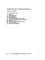
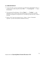
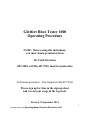
Göttfert Rheo Tester 1000 Operating Procedure NOTE: Before using this instrument, you must obtain permission from Dr. Faith Morrison (487-2050, cell 906-487-9703, [email protected]). Technician assistance: Tim Gasperich 906-487-2841 Please sign up for time in the sign-up sheet and record your usage in the log-book. Revised 19 September 2014 1 29 Sept 2014 minor edits Operating Manual Goettfert Rheotester 1000 Gottfert Rheotester 1000 Operating Manual TABLE OF CONTENTS (0) (I) (II) (III) (IV) (V) (VI) (VII) (VIII) (IX) (X) A FEW USEFUL TIPS START-UP SERVICE MODULE SETUP MODULE MEASURE MODULE TOOL PREPARATION AND LOADING LOADING THE SAMPLE AND THE PISTON RUNNING A TEST SAVING AND ANALYZING THE DATA EVALUATE MODULE CLEANING AND WIND-UP 2 29 Sept 2014 minor edits Operating Manual Goettfert Rheotester 1000 Figure 1: The Goettfert Rheotester 1000 is a bench-scale capillary rheometer. The upper orange chamber houses the hydraulic drive. The stainless steel cylinder in the center houses the barrel and the heating units for the barrel. Electronics are housed in the lower portion, and the instrument is computer-controlled. 3 29 Sept 2014 minor edits Operating Manual Goettfert Rheotester 1000 (0) A FEW USEFUL TIPS The Göttfert Rheo Tester 1000 can be used for capillary viscosity measurements at temperatures ranging from the ambient to 400C. It is necessary to use thermal gloves when working with this instrument at elevated temperatures. Use of a lab-coat is advisable to protect clothing from any sticky plastic. Safety glasses with side shields are required. Brass or copper gauze (Scotchbrite copper scrubbies) and a clean rag (cotton fabric) will come in handy when it comes to post-experiment cleaning of the instrument. Please be very careful when handling the various tools and components of the instrument. The pressure transducer and the melttemperature thermocouple are particularly delicate and expensive parts. The USB ports on the computer are USB-1 and therefore you will need to borrow the USB sticks provided to get your data off the computer. In case of a difficulty or an emergency, please contact Dr. Faith Morrison (906-487-2050; cell phone 906-487-9703) and /or Public Safety (906-487-2216). In an emergency dial 911. Please follow all the precautions mentioned in this manual. Please give your suggestions for improvement of this manual to Professor Morrison. 4 29 Sept 2014 minor edits Operating Manual Goettfert Rheotester 1000 (I) START-UP 1) Start WINDOWS XP on the Göttfert PC. The computer must be on before turning on the test station. 2) Inspect the barrel and make sure it is clean. Clean if necessary (check logbook for prior user). 3) Insert the key into the test station and turn it 90 COUNTERclockwise. Also turn the red knob on the front of the instrument panel 90 clockwise to set it to position 1. A green light on the front of the instrument panel should come on, signifying that the instrument is on. 4) Double click on “service.exe” on the desktop to start the "SERVICE" module. WARNING: If you do not do these steps in order, you may see an error related to the communication between the base station and the computer (ESP connection failed/error). If this occurs, close down both units and re-start strictly following the order above. 5 29 Sept 2014 minor edits Operating Manual Goettfert Rheotester 1000 (II) SERVICE MODULE 1) Click on "Test Parameter"—> Click on "Temperature Correction" —> Click on the "Reference Temperature" box and choose a reference temperature (choices are 100, 190, or 300 ) closest to the desired test temperature from the choices in the box at the bottom of the screen. Refer to Table 1 and check the steel- and melt-temperature corrections. Enter the appropriate values if needed—> Click on “SET” and then “OK” to exit Table 1: Temperature corrections for the different reference temperatures Reference Temp Steel Temp I (C) Steel Temp II (C) Melt Temp (C) 100 0.1 -0.6 -0.3 190 0.7 -0.7 -0.9 300 1.2 -1.3 -1.6 2) Click on "Test Device" —> "Device Type" ----> Rheo Tester 1000 ----> OK 3) Click on "Test Device" —> "Pressure Transducer" ----> 1400-173011194/1120/280 for using 1400 bar transducer or 200-371229/160/40 for 200 bar transducer. Click on “SET” and then “OK”. Note: Before using the 200-bar transducer, please make sure that the pressure will not exceed 200 bars during the entire experiment. The pressure can be estimated prior the experiment by using the Bagley plot obtained from previous 20/1 and 30/1 experiments. 6 29 Sept 2014 minor edits Operating Manual Goettfert Rheotester 1000 4) Click on "Test Device" —> "Capillary" —> choose the desired type (options are given in Table 2). Click on “SET” and then “OK”. Table 2: Selection guide for capillaries L (mm) D (mm) L/D Capillary Code 5 1 5 Roundhole 5/5/1/0/180 20 2 10 20 1 20 Roundhole 20/20/1/0/180 30 1 30 Roundhole 30/30/1/0/180 40 1 40 Roundhole 40/40/1/0/180 (“1” refers to the capillary diameter in and “180” refers to the capillary entrance angle in degrees, meaning it is a blunt entry) 5) Click on "Test Parameter" ----> Click on "Exit" to come out of the SERVICE module. 7 29 Sept 2014 minor edits Operating Manual Goettfert Rheotester 1000 (III) SETUP MODULE 1) Double click on “setup.exe” on the desktop to open the "SETUP" module. The desired experimental parameters are specified in this module. 2) If the desired Setup file already exists, click on "File" ----> "Load Setup" , choose it and proceed to Step 8. If a new Setup needs to be created, proceed as shown below. 3) Click on "Test Chamber" ----> Verify that the capillary and the transducer information contained in this module corresponds to the one entered in the SERVICE module. 4) Click on "Material" ----> a) "Material Designation" ----> enter the material name and the directory you want the experimental data to be saved in, making sure that the path to this directory has been created. b) "Test Temperature" ----> In the "Steel Temperature" box enter the desired test temperature in C, and also verify that the reference temperature and the corresponding temperature corrections are correct. 5) Click on "Measurement" ----> click on "Measurement / Set Values Configuration" ----> a) Enter the “Melting Time” (minimum of 20 minutes). Please make sure that the melting time is long enough to melt the polymer at the test temperature. b) Select the desired working mode: constant velocity (V constant), constant pressure (P constant), or user-defined. Note: Currently we use V constant mode. c) If you select constant velocity and desire to run a rate sweep (several runs in series at different piston speeds), go into the "Set Values" box and enter the desired shear rates/piston speeds. To enter a new value, type the piston speed/shear rate in the box and then go into the "Set Value Calculation" box and click on "Add". To set the time limit for each shear rate/piston speed go to the "Time Limit" column. Click on the value corresponding to the one in the shear rate/piston speed column and enter the time in mm:ss (minutes : seconds) for which you desire that particular shear rate/piston speed to be maintained. Then click on "Change" to register this time limit. After you are done specifying the values (there are a maximum of 20 values), go into the "Set Value Calculation" column. Currently, we set the piston speed/shear rate in an increasing order. d) Set “Take Over Tolerance” to 1%. This value is used to determine when the piston speed needs to be changed before the time limit. If the change in pressure reading is within the take-over tolerance and is maintained for a certain amount of time (called 8 29 Sept 2014 minor edits Operating Manual Goettfert Rheotester 1000 “comparison time” see the part e), the piston will move to the next set speed and the program assumes that a steady state is reached. e) Set “Comparison Time” to more than 10 seconds. This comparison time should be longer when doing the high piston speed (>3 mm/s) for more accurate pressure readings. 6) Click on “File” "Save Setup" and save the file systematically under an appropriate name. 7) Choose “File” “Exit” to exit setup. 8) Go into the "MEASURE" module. NOTE: The instrument will begin to heat up once you enter the "MEASURE" module. This is signified by the two red lights on the front panel of the test-station. 9) A Setup file needs to be loaded in this module. If a new Setup file is created, it automatically gets loaded into the module 9 29 Sept 2014 minor edits Operating Manual Goettfert Rheotester 1000 (IV) MEASURE MODULE 1) If a new Setup file is created, it automatically gets loaded into the "MEASURE" module. If you desire to use an older Setup file, click on "File" ----> "Load Setup File" ----> choose the desired file. 2) The instrument will start heating up. Click on "Display" ----> "Test Data" ----> the temperatures in the two barrel zones will be shown on the screen as PT1001 and PT1002. While the test temperature is being achieved, it is advisable to get the tools ready, in order to save time. 3) Display a “Hot” sign as the instrument heats up. Display a “Notice of Unattended Operation” if you leave the instrument unattended to warm up. 10 29 Sept 2014 minor edits Operating Manual Goettfert Rheotester 1000 (V) TOOL PREPARATION AND LOADING 1) Choose the capillary you need and select the appropriate distance ring and the capillary nut from Table 3. The lock nut with no deep hollow in the center is lock nut type A. Table 3: Selection guide for capillary, distance ring, and capillary nut Capillary L/D Dist. ring length (mm) Locking nut type 5 20 A 20 10 A 30 ---- A 40 ---- B 2) Clean all the tools prior to starting the experiment. Make sure that the piston, capillary, distance ring, capillary nut, (melt-temperature thermocouple—not currently in use, ) and pressure transducer are free from dust, grime, and polymer residue. DO NOT use any solvent to clean the pressure transducer and be very careful with the tip of the transducer. 3) Using graphite paste or high temperature lubricant, coat the threaded portions of the pressure transducer and the capillary nut with a thin film. WARNING: (a) The paste or lubricant MUST be applied to prevent the tools from shearing off due to expansion on heating. (b) Do not use too much paste or lubricant. (c) It is advisable to use disposable latex rubber gloves when working with the paste, as it is very sticky and greasy. 4) Mount the capillary on the distance ring, and fit the ring into the groove in the capillary nut. NOTE: The capillary must be inserted right-side up. The right side is the side with the slightly raised portion. The bottom of the capillary is completely smooth. If the capillary is inserted upside-down, the run will be wasted and polymer will flow all over the bottom of the instrument, making a mess that is difficult and tedious to clean up. 11 29 Sept 2014 minor edits Operating Manual Goettfert Rheotester 1000 Figure 2: The 20/1 capillary and the 40/1 capillary and their capillary nuts. Note that the nut for the 40/1 capillary has a recess, while the 20/1 capillary requires a distance ring. The assembled capillaries have the same linear heights as shown at right. Note the slight elevation of the central portion, which indicates that the capillaries are in right-side up. WARNING: If elevated test temperatures are used, you MUST use thermal gloves for the rest of the tool-loading procedure. The instrument can be VERY HOT!! 5) After the barrel has reached the desired test temperature, wait 10 minutes to allow the barrel to be heated uniformly, and then insert the capillary assembly into the instrument. Using a mirror, make sure that the key on the side of the capillary matches the keyway on the underside of the barrel. Use the hexagonal sickle spanner to tighten the capillary nut until it is hand-tight, then unscrew it 1/4 turn (90). WARNING: The capillary MUST be unscrewed 1/4 turn to prevent damage due to expansion on heating. 6) Carefully screw in the pressure transducer. Turn the transducer in until it is finger-tight, then unscrew it 1 turn (360). DO NOT force the pressure transducer if it does not turn smoothly. Instead, reaffirm that its threads are clean and that they are not damaged. Also check that the hole for the pressure transducer is clean. Use the cleaning tool to do this (please turn to "Hole for the pressure transducer" in Section (X) to see how this is done). 7) WARNING: The transducer MUST be unscrewed 1 turn to prevent damage due to expansion on heating. 12 29 Sept 2014 minor edits Operating Manual Goettfert Rheotester 1000 Figure 3: The 1400 bar pressure transducer is shown above. The pressure-sensing end is to the right. The orange portion houses the electronics and the connection that is made to the rheometer. 8) Allow the capillary and the pressure transducer about 10-15 minutes to attain the test temperature. Then tighten the capillary using the spanner till it is finger-tight. Also tighten the transducer by hand till it is finger-tight (DO NOT over-tighten either tool). Connect the measuring cable to the transducer taking care not to twist or bend it. WARNING: The capillary MUST be tightened before the pressure transducer in order to prevent the diaphragm of the transducer from getting damaged. Figure 4: The spanner for the capillary is shown above. 9) Insert the melt-temperature thermocouple into the hole provided, if available (Note: this was broken in 2000 and has not been replaced). It slides in easily about half-way and then requires a firm push to go in completely. DO NOT try to force the thermocouple in, otherwise you may bend it. Also, DO NOT tighten the threaded sleeve. Connect the cable to the back of the thermocouple. Wait a few minutes for the thermocouple to attain the test temperature. The screen will also display the thermocouple reading as FeKo1. Finally, tighten the threaded sleeve of the thermocouple until it is finger-tight. 13 29 Sept 2014 minor edits Operating Manual Goettfert Rheotester 1000 10) The next step is to calibrate. WARNING: The barrel MUST be completely clean and free from any plastic residue when this is being done. 11) Click on "Calibrate" in the MEASURE module so that the transducer is calibrated. The message "Transducers are being calibrated" appears in the lower left-hand-side of the screen when the calibration is in progress. It is replaced by another message "Calibration finished" when the process is completed. Record the initial pressure and status in the notebook. 14 29 Sept 2014 minor edits Operating Manual Goettfert Rheotester 1000 (VI) LOADING THE SAMPLE AND THE PISTON WARNING: Before loading the polymer in the barrel, make sure that the initial pressure is about 0 and piston displacement is 0. If initial pressure is more than 5 before loading the sample, please check the cleanness of the transducer hole using the cleaning tool (Apply section X part 9) 1) With the help of a disposable paper cup, load a few dozen pellets of the sample into the barrel. Use a tamping rod to compress the charge and release the entrapped air. You may use a fair amount of force here: the goal is to fully pack the barrel, leaving no air. Keep loading the sample, periodically using the tamping rod to drive away the air. Stop loading the sample when the level of the sample is approximately 1.0 cm below the top end of the barrel. Note: Overloading the barrel will cause polymer to be forced out the top of the barrel and this can lead to polymer burning onto the hot barrel. This is difficult to clean. 2) When the sample has been loaded, mount the piston. To do this, put the tip of the piston in the barrel, pull up on the sleeve, insert the piston into the sleeve, and release the sleeve. Please make sure that the piston has been properly secured. 3) Close the safety guard of the test station. 4) Gently lower the piston using the slow downward button on the front of the instrument panel. Stop when the piston is just in contact with the sample. WARNING: The safety door of the instrument MUST be closed otherwise the piston will NOT move. DO NOT lower the piston too much; otherwise, it will press down on the halfmolten plastic. This will damage the barrel, the capillary, and the pressure transducer. 5) Place a metal tray or some aluminum foil under the capillary exit in order to collect the sample as it comes out during the test. 15 29 Sept 2014 minor edits Operating Manual Goettfert Rheotester 1000 (VII) RUNNING A TEST 1) There are two ways of starting the test: letting the Goettfert time the melting period, or timing the melting period yourself. The disadvantage of letting the Goettfert do the timing is that it advances the piston based on a pressure criterion. If the sample is low in viscosity, the polymer will be pushed out during the loading, wasting the sample. a) Computer timing method: When the sample has been loaded and the piston is in position, click on "Start" in the MEASURE module. The piston will start moving at a low speed to pack the polymer in the barrel until it reaches a certain pressure (~4.7 bars). The instrument will then wait for the specified melting time which will count down in the lower left hand corner of the measurement mode. After the melting time, the test will start automatically and the piston will start to descend. b) Manual timing method: When the sample has been loaded and the piston is in position, start timing the melting time (minimum of 10 minutes). After the desired melting time, click on “Start” in the MEASURE module. The piston will start moving at a low speed to pack the polymer in the barrel until it reaches a certain pressure (~4.7 bars). The instrument will then show the specified melting time in the lower left-hand corner of the measurement mode. When you wish to start the test, click on “Take Over” (the same button as the “Start”) once. The test will start and the piston will start to descend. 2) If you wish to start the test before the melting time is over (for example, if you overestimated the melting time and the plastic is already molten but there is still some time left for the piston to descend), you can click on "Take Over" in the MEASURE module and start the test immediately. Similarly if you do not wish to wait for the time allotted for the existing shear rate to be completed, you can click on "Take Over" to record the data at that shear rate and immediately bring the next shear rate into operation. 3) Collect the plastic extrudate in a metal tray or on aluminum foil. Please use thermal gloves when handling the extrudate. Try not to let extrudate to tangle up. NOTE: If at any time during the test you wish to terminate it, either press the "F3" button on the front panel of the test station or click on "Break" in the MEASURE module. Never hit “End”. 16 29 Sept 2014 minor edits Operating Manual Goettfert Rheotester 1000 (VIII) SAVING AND ANALYZING THE DATA 1) If you wish to save the test data, click on “File,” then "Save Test Data" and give the desired file name for the data. NOTE: It is advisable to keep the test station at the test temperature so that the cleaning procedure is easier. Therefore, please clean the barrel and the other components BEFORE you exit the MEASURE module (please refer to Section (X) of this manual for details). If you wish to analyze your data immediately after the run is complete you will need to go into the Evaluate module. DO NOT exit from the Measure module, because if you do so the barrel will start to cool down and the molten polymer will solidify while it is in the barrel and will be hard to remove. 2) Click on "End" in the Measure module (or on "File" and then on "End Program") to exit from the Measure module, ONLY after making sure that the barrel and other components are clean. 3) Data analysis can be carried out in the "EVALUATE" module. 17 29 Sept 2014 minor edits Operating Manual Goettfert Rheotester 1000 (IX) EVALUATE MODULE WARNING: Files saved in the "Evaluate" module DO NOT retain raw data. 1) Click on "Files" —> "Load New Test Data" —> select the data file to be analyzed. 2) A number of options for processing the data are available in this module. 3) If you need to compare one set of data with another, load one file first and then click on "Merge Test Data" to load the other set of data for comparison. 4) To save the evaluated data, click on "Files" —> "Save Evaluated Data" —> specify a different file name to save the evaluated data. DO NOT save the evaluated data under the same name if you want to retain the raw, real-time data. If you do this, the old data file will be overwritten and the real-time data will be lost. You may, however, save the evaluated data under the same file name if you do not wish to store the real-time data. 5) To transfer test files with real-time data onto a USB drive, use "File Manager" in the "Main" application of WINDOWS. DO NOT use the "Evaluate" module for this. Only low-speed USB drives work with this computer; one is provided. 6) Click on "Files" —> "End Program" to exit the "Evaluate" module. 18 29 Sept 2014 minor edits Operating Manual Goettfert Rheotester 1000 (X) CLEANING AND WIND-UP NOTE: Use of thermal gloves and lab-coat is strongly advisable. Safety glasses with side shields are required in the laboratory at all times. The cleaning procedure is most effective when the machine is at the test temperature and the plastic residue is still in the molten form. Please ensure that the instrument is at the test temperature throughout the clean-up. Please be VERY CAREFUL when removing the hot parts, otherwise you might damage them, and more importantly, you might hurt yourself! 1) Melt-temperature thermocouple: (if applicable) This tool MUST be removed first. Disconnect the cable, gently unscrew the threaded sleeve and remove the thermocouple. Carefully wipe off any molten plastic from the tip of the thermocouple with a soft cloth. Allow the thermocouple to cool completely before putting it away. Please be careful. DO NOT bend the thermocouple. 2) Piston: Close the safety door of the instrument and raise the piston using either the "slow up" () or the "fast up" (both buttons ) button on the front panel of the test station. If there is molten plastic near the top of the barrel, wipe this off immediately. Continue to raise the piston. When the piston has reached its uppermost position, carefully remove it and wipe off the molten plastic with a soft cloth and copper wool. Use the brass brush to clean stubborn residue, but be gentle so as to prevent damage to the piston. As with all the above parts, please allow sufficient time for the piston to cool before putting it away. 3) Pressure transducer: Disconnect the cable and gently unscrew the transducer. Using a soft cloth, wipe off the graphite paste and any molten polymer from the transducer. If necessary, use a soft brass brush to remove troublesome residue, but please be VERY GENTLE especially when cleaning the flat measuring end of the transducer. This part is very delicate and any damage to it will affect its sensitivity and also the accuracy of the data. NEVER use any solvent to clean polymer residue from the transducer. Allow the transducer to cool completely before putting on its protective cap and returning it to its box. 4) Capillary: NOTE: The thermocouple and the pressure transducer MUST be removed before the capillary assembly, otherwise the tip of the thermocouple may get sheared off and the diaphragm of the pressure transducer may be damaged. (Note: this is how the thermocouple was damaged in 2000.) Using the spanner, unscrew the capillary nut and remove the capillary assembly. If the capillary does not drop out of the assembly tap it with a long brass rod. Do not use any stainless steel tools on the Goetfert. Wipe off the graphite paste and molten polymer from the capillary nut, the distance ring, and the capillary. Once again, allow the 19 29 Sept 2014 minor edits Operating Manual Goettfert Rheotester 1000 capillary assembly to cool down before putting it away. NEVER poke into the capillary with a pin, tweezers, or other hard objects. This will damage the capillary. Please label the capillary with the type of polymer inside it for the information of the next user. Displace unusual materials with polyethylene before shutting down operations. 5) Barrel: Cut out a small square of copper gauze or a circle of cotton and lay it flat on the top of the barrel. Use the cleaning piston to push the gauze down the barrel. While doing this, also rotate the cleaning piston. Push the cleaning piston down as far as possible and then pull it back up while simultaneously rotating it. Discard the gauze and use a fresh square until the barrel is clean. Use a flashlight to check that the barrel is clean. In order to clean stubborn residue from the inside of the barrel, use the tubular brass brush. Never use a steel wire brush. NOTE: Use the tubular brush only when absolutely necessary. Excessive use of this brush may damage the inside surface of the barrel. Also make sure to clean the tubular brush thoroughly after use. 6) Hole for the pressure transducer: Remove the protective cap on the cleaning tool. Coat the threaded portion of the tool with graphite paste or high-temperature lubricant. Using the knurled ring on the tool, screw it into the hole till it is finger tight (DO NOT overtighten), then unscrew it 1/4 turn. Turn the green plastic handle clockwise, applying gentle pressure towards the hole. Unscrew the tool and clean the plastic residue immediately, using a soft cloth. Repeat until the hole is completely clean. Use a flashlight to check that the hole is clean. Clean the tool thoroughly, allow it to cool, and put on its protective cap before putting it away. Check the barrel once again just to make sure no plastic from the hole has been accidentally pushed into it. Clean it immediately if so. Figure 4: The cleaning tool for the pressure-transducer hole appears above. A small threaded appendage (shown at right) extends from the tip of the cleaning tool and fits into the hole that connects the plastic in the barrel to the end of the pressure transducer. Care should be taken not to break off the cleaning tip. 7) Winding up: Turn the red knob on the instrument panel 90 counterclockwise to set it to position 0. Turn the key in the instrument 90 clockwise and remove it. This will shut the instrument off. Exit from the winRHEO application in WINDOWS. Shut down the computer. 20 29 Sept 2014 minor edits Operating Manual Goettfert Rheotester 1000 8) Please place a sign near the instrument warning others that it is hot. It is also essential that you record your usage in the log-book. Please mention your name, phone number, the date and time of the experiment, test conditions used, and the material used. Please write legibly. This will be helpful if subsequent users need to contact you for guidance or advice. Please also write down any problems that you may have encountered during the test and any suggestions that you might have. 21 29 Sept 2014 minor edits Operating Manual Goettfert Rheotester 1000