1
Interfaces of the Device
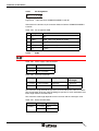
The maximum cable length depends on the baud rate used.
Table 4-31
Baud rate CAN
Baud rate
Cable length
20 kBit/s
1000 m
125 kBit/s
500 m
250 kBit/s
250 m
500 kBit/s
100 m
1000 kBit/s
25 m
4.4.1.3
Termination
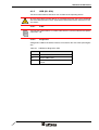
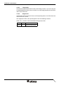
Terminate the CAN bus at both ends by terminating resistors (120 Ohm).
4.4.1.4
Diagnostics LEDs
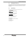
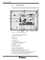
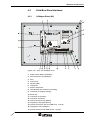
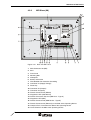
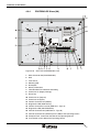
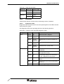
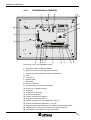
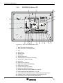
Diagnostics LEDs are located at the rear of the operating device. The LEDs show the
states of the bus system.
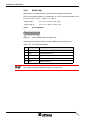
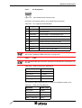
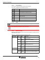
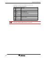
Table 4-32
Functions of the CAN diagnostics LEDs
Designation
Color
State
Function
SYS
Green
On
Communication in progress
Green
Flashes
cyclically
Communication stopped
Green
Flashes
irregularly
Configuration is missing or contains errors
Yellow
Flashes
cyclically
Bootstrap loader active
Yellow
Flashes
irregularly
Hardware error / system error
Red
On
CAN error
Yellow
On
Transmission on CAN bus in progress
COM
4.4.1.5
Diagnostics Interface (X6)
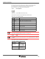
To be able to use the diagnostics interface you need the System Configurator Software SyCon. You can obtain this software directly from Sütron electronic.
The diagnostics interface is connected with the serial interface of the PC.
4.4.1.5.1
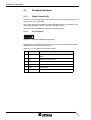
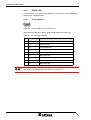
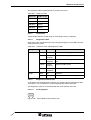
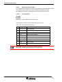
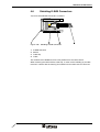
Figure 4-20
Pin Assignment
9 pin D-SUB male connector strip
4-27