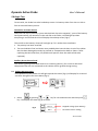
1
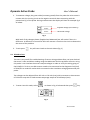
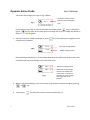
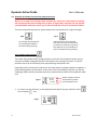
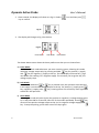
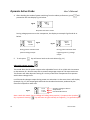
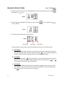
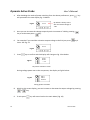
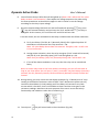
Dynamic Active Probe User’s Manual 4. After deciding the mode of power switching from the above preferences, press proceed to the next display Fig. 14 below. will 12.8 V 0.0 A -.-- Fig.14 No power activation screen During voltage power out to the component, the display as example Fig.15 and 16 as below: 12.8 V 8.3 A 1.54 Fig.15 Fig.16 During power activation with positive voltage output 5. To exit press -12.8 V - 8.3 A 1.54 During power activation with negative ground (-) voltage output key will return back to the main Menu (Fig. 11) Adjustable voltage output: This mode allow the DC power output to be adjustable from 1.0V to 12.0V with increments or decrements of 1.0V each step with a constant amperage output of 5.0 Amps maximum. This feature will allow dynamic testing of a variety of electrical components that operate within these voltage limits. It will show the voltages output during power out activation. At the same time it will display (example: Fig. 17) the amperage drawn and the calculated resistance produced by the electrical component under test. Fig.17 5.0 V 1.6 A 3.13 Set point voltage to device Amps Drawn Calculated Resistance Note: Under this mode, the set voltage will always be a positive (+) output to the tip when key is pressed. Pressing key will have no effect thereby no negative (-) or ground output. 10 Version 1502