1
Dynamic Active Probe
User’s Manual
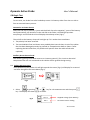
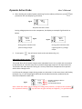
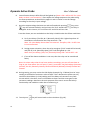
2. To measure voltage, the green cable (common ground) from the probe has to be come in
contact with the running circuit at the negative terminal when measuring with the
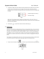
pointed end (+) of the probe. During measurement the display will show an example Fig.3
as below:
12.6 V
Supplied Voltage (from Battery)
12.3 V
Measured Voltage
Fig.3
With both of the voltages shown (Supplied and Measured) we will notice if there is a
difference. A difference of more than 0.5V will warrant a check on the circuit to determine
the cause of the problem.
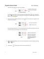
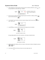
3. To exit press
key will return back to the main Menu (Fig. 2)
5.2 ECU Wire Test:
This test is very useful for troubleshooting of sensor wiring problem after you have checked
the sensor’s Volts and Ohms reading using the Multimeter and the problem still exist. Using
this probe it can simulate the sensors output voltages in order to verify the wiring going to
the ECM/ECU. To do so, an OBD scanner needs to be connected to the diagnostic link (DLC)
of ECM/ECU to read the results while connected to the simulation voltage generated by the
probe.
The voltages can be adjusted from 0.5 Volt to 5.0 Volt (max) with increments or decrements
of 0.5V each step with a fixed constant amperage output of 20 milliamps (max).
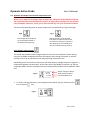
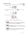
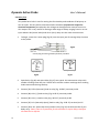
1. To enter into this mode, select
as shown in Fig. 4 below and then press
Fig.4
6
Version 1502
key.