1
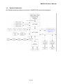
WADE-8156
Intel® Core™ 2 Duo Desktop
Q965 Mini ITX
User’s Manual
Rev. 1.0
2007/04/25
WADE-8156 User’s Manual
Copyright
All rights reserved. The information contained in this guide has been validated and
reviewed for accuracy. No patent liability is assumed with respect to the use of the
information contained herein. While every precaution has been taken in the preparation of
this guide, the Manufacturer assumes no responsibility for errors or omissions.
No part of this publication may be reproduced, stored in a retrieval system, or transmitted in
any form or by any means, electronic, mechanical, photocopying, recording, or otherwise,
without the prior written permission of Manufacturer.
Trademark
Intel®, Pentium® and Celeron® are registered trademarks of Intel® Corporation.
Microsoft® and Windows® are registered trademarks of Microsoft Corporation.
All products and company names are trademarks or registered trademarks of their
respective holders.
These specifications are subject to change without notice.
Technical Support
We hope you to get the maximum performance from your products and be willing to help if
running into technical difficulties. For the most frequently asked questions, it’s easily found
answers from the product documentation and usually a lot more detailed, so please take
reference to this manual first. If the answer still can not be found, gather all the information
or questions applying to the problem, and with the product on hand, contact your distributor,
sales representative, or customer service center for technical support. Most problems
reported are minor and able to be easily solved over the phone. In addition, free technical
support is available and always ready to give advices on application requirements or
specific information on the installation and operation of any of our products.
Please have the following information ready before you call:
1. Product name and serial number
2.
3.
4.
5.
Description of your peripheral attachments
Description of your software (operating system, version, application software, etc.)
A complete description of the problem
The exact wording of any error messages
2 / 55
WADE-8156 User’s Manual
How to Use This Manual
This manual is written for the system integrator, PC technician and knowledgeable PC end
user. It describes how to configure your WADE-8156 to meet various operating
requirements. The user’s manual is divided into four chapters, with each chapter
addressing a basic concept and operation of the server board.
Chapter 1: Introduction - presents what you have inside the box and gives you an
overview of the product specifications and basic system architecture for the WADE-8156
board.
Chapter 2: Hardware Configuration Setting - shows the definitions and locations of
Jumpers and Connectors so that you can easily configure your system.
Chapter 3: System Installation - describes how to properly mount the CPU, main memory,
and M-System Flash disk for a safe installation. It will also introduce and show you the
driver installation procedure for the Graphics Controller and Ethernet Controller.
Chapter 4: BIOS Setup Information - specifies the meaning of each setup parameter, how
to get advanced BIOS performance and update to a new BIOS.
Note:
(1) Memory type support dual-channel interleaved mode assuming DDR2, all DIMMs
in a system must be of the same type, the speed in all channels is the speed of
the slowest DIMM in the system.
3 / 55
WADE-8156 User’s Manual
Table of Content
1.
Introduction.................................................................................................................8
1.1
Description...........................................................................................................8
1.2
Packing Check List..............................................................................................9
1.3
Specifications ....................................................................................................10
1.4
System Architecture..........................................................................................12
1.5
Dimensions ........................................................................................................13
2.
Hardware Configuration Setting..............................................................................15
2.1
Board Layout .....................................................................................................15
2.2
Jumpers & Connectors .....................................................................................16
2.3
Jumpers/Connectors Setting............................................................................17
2.3.1
2.3.2
2.3.3
2.3.4
2.3.5
2.3.6
2.3.7
2.3.8
2.3.9
2.3.10
2.3.11
2.3.12
2.3.13
2.3.14
2.3.15
2.3.16
RTC CMOS Clear Select (JP1) ....................................................................17
Internal Audio for Chassis (AUDIO1)............................................................17
Audio Connector (AUDIO2) ..........................................................................17
Auxiliary/CPU/System Connectors (AUX_FAN1, CPU_FAN1, SYS_FAN1) .17
CD-In from CD-ROM (CD1)..........................................................................17
COM1 / COM2 Connector (COM1, COM2) ..................................................17
GPIO Connector (GPIO1).............................................................................18
PS/2 Keyboard & Mouse (KBMS1)...............................................................18
Front Side Indicators (PANEL1) ...................................................................18
24-pin ATX Power Connector (PWR1)..........................................................18
4-pin ATX Power Connector (PWR2)............................................................18
Serial ATA 1/2/3/4 Connectors (SATA1, SATA2, SATA3, SATA4) .................18
Internal Speaker Connector (SPK1) .............................................................19
LAN 1/2 & USB 1/2/3/4 Connectors (USB2LAN1, USB2LAN2)....................19
Internal USB 5/6/7/8 Connectors (USB1, USB2)..........................................19
VGA Connector (VGA1) ...............................................................................19
4 / 55
WADE-8156 User’s Manual
3.
3.1
System Installation ...................................................................................................21
Intel® µFC-LGA775 Processor...........................................................................21
3.1.1
Installing Intel® Core™ 2 Duo / Pentium® 4 / Celeron® D CPU ......................21
3.2
Installing 1 U Cooler for Intel® µFC-LGA775 Processor..................................22
3.3
Main Memory......................................................................................................23
3.4
Installing the Mini-ITX........................................................................................24
3.4.1
3.4.2
4.
4.1
Dual Marvell Gigabit Ethernet Controllers ....................................................24
Drivers Support ............................................................................................24
BIOS Setup................................................................................................................26
Entering Setup ...................................................................................................26
4.1.1
4.1.2
4.1.3
4.1.4
4.1.5
4.1.6
4.1.7
Main Menu....................................................................................................26
Advanced Setting .........................................................................................27
Advanced PCI/PnP Setting...........................................................................41
Boot Settings ................................................................................................44
Security Settings ..........................................................................................46
Advanced Chipset Settings ..........................................................................47
Exit Options ..................................................................................................52
Appendix A: Watchdog Timer Programming ................................................................54
Appendix B: GPI/O Programming ..................................................................................55
5 / 55
WADE-8156 User’s Manual
Revision History
Revision
Date
Rev.1.0
Apr. 2007
Comment
Initial released
6 / 55
WADE-8156 User’s Manual
CHAPTER 1
7 / 55
WADE-8156 User’s Manual
1.
Introduction
1.1
Description
The leading WADE-8156 Mini-ITX adopts Intel® energy-efficient dual-core processing to fit
a high performance Intel® CoreTM 2 Duo Desktop based in the LGA775 package processors
and compatible for high-end computing applications with PCI-E bus architecture to adapt to
today’s demands and keep complete compatibility with hardware and software designed.
The onboard devices support one PCI Express x16 slot for flexible expansibility of graphics
interfaces, integrated graphics, and onboard dual Marvell Gigabit Ethernet controllers. It’s
beneficial to build up a high performance and fast transmission availability system for VARs,
or system integrators.
The WADE-8156 supports Intel® LGA775 CoreTM 2 Duo Desktop processors in E6000, 600,
500, 400, and 300 sequences via Intel® Q965 and ICH8 chipset integrated GMA 3000
graphics with DVMT 4.0 display memory up to 256 MB for optional dual display function by
VGA/LVDS and VGA/DVI through optional ADD2 card. The board supports two DIMMs up
to 4 GB SDRAM with dual channel DDR2 533/667/800, enhanced onboard four SATA
high-speed data transferring at up to 300 MB/s, integrated Realtek ALC883 7.1 + 2 CH high
definition audio codec. The onboard Super I/O Winbond W83627DHG chipset supports two
RS-232 serial port interfaces, Hardware Monitor function, eight Hi-speed USB 2.0 ports,
and two 6-pin Mini-DIN connectors for PS/2 mouse and keyboard. Besides, one 24-pin
standard connector designed to support ATX power function, and a feature of CPU
overheat protection will provide user more security and stability.
Combing with these outstanding features in the Mini-ITX form factor, WADE-8156 is
definitely the most excellent choice for embedded applications like Network, Point of Sales
(POS), automated KIOSKs, security products, medical instruments, and gaming machines.
8 / 55
WADE-8156 User’s Manual
1.2
Packing Check List
The WADE-8156 package includes the following basic items accompany with this manual.
One WADE-8156 Mini ITX board
Two Serial ATA cables
One Serial port cable for COM2
One USB 2.0 cable
One I/O Shield
One Supporting CD-ROM contains User’s Manual and internal VGA display driver
and Marvell Gigabit Ethernet network controller driver and on board devices
drivers
If any of these items is damaged or missed, please contact your vendor and save all
packing materials for future replacement and maintenance.
9 / 55
WADE-8156 User’s Manual
1.3
Specifications
System
CPU
Intel® Core™ 2 Duo Desktop / Pentium® 4 / Celeron® D processor in the
LGA775 package (E6000, 600, 500, 300 sequences)
FSB
1066/800/533 MHz
BIOS
AMI BIOS with 8 Mb SPI Flash EEPROM
System Chipset
Intel® Q965 + ICH8
I/O Chip
Winbond W83627DHG I/O controller
2 x 240-pin DIMM sockets support dual channel DDR2 533/667/800
System Memory
SDRAM
Max. up to 4 GB memory
Storage
4 x Serial ATA 300 ports
RAID
Optional ICH8R supports RAID 0, 1, 5, 10 function
Watchdog Timer
Reset: 1 sec.~255 min. and 1 sec. or 1 min./step
Monitoring system temperature, voltage, and cooling fan status.
H/W Status Monitor
Auto throttling control when CPU overheats.
System automatically restored on recovery of AC power loss.
GPIO
On-board programmable 8-bit Digital I/O interface
Expansion
1 x PCI-E x16 interface
MIO
Internal I/O
Back Panel I/O
1 x RS-232, 4 x USB 2.0
1 x VGA, 1 x Audio jack, 2 x RJ-45, 1 x RS-232, 4 x USB 2.0, 1 x KB,
1 x Mouse
Display
Chipset
Intel® Q965 Integrated Intel® GMA 3000 graphics
Display Memory
Intel® DVMT 4.0 supports up to 256 MB video memory
Resolution
Analog display : up to 2048 x 1536 @ 75Hz (QXGA)
Digital CRT/HDTV : up to 1920 x 1080 @ 85 Hz
VGA/LCD Interface
DSUB-15 connector for VGA output
LVDS
Optional Chrontel CH7308 LVDS transmitter by ADD2 card
DVI
Optional Chrontel CH7307 DVI transmitter by ADD2 card
10 / 55
WADE-8156 User’s Manual
Audio
HDAC
Realtek ALC883 7.1 + 2 CH audio interface
Audio Interface
Mic in, Line in, CD Audio in, Line out, Rear out and Center/Subwoofer out
Ethernet
Chipset
Dual Marvell® 88E8053 PCI Express™ Gigabit Ethernet controllers
Ethernet Interface
IEEE 802.3 10BASE-T/100BASE-TX/1000BASE-T
Mechanical & Environmental
+3.3 V @ 3.3 A, +5 V @ 1.9 A, +12 V @ 4 A, 5 Vsb @ 500 mA (w/ Intel®
Power Requirement
Core™ 2 Duo E6700 2.66 GHz & 2 x 512 MB DDR2 800 MHz SDRAM in
Dos Mode)
Power Type
24-pin ATX power connector, 1x 4-pin ATX 12V power connector
Operating Temperature
0~60°C (32~140°F)
Operating Humidity
0%~90% relative humidity, non-condensing
Size (L x W)
6.69" x 6.69" (170 mm x 170 mm)
Weight
0.94 lbs (0.43 Kg)
11 / 55
WADE-8156 User’s Manual
1.4
System Architecture
All of details operating relations are shown in WADE-8156 system block diagram.
12 / 55
WADE-8156 User’s Manual
1.5
Dimensions
Unit: mm
13 / 55
WADE-8156 User’s Manual
CHAPTER 2
14 / 55
WADE-8156 User’s Manual
2.
Hardware Configuration Setting
This chapter gives the definitions and shows the positions of jumpers, headers and
connectors. All of the configuration jumpers on WADE-8156 board are in the proper position.
The default settings shipped from factory are marked with an asterisk ( ).
In general, jumpers on the Mini ITX are used to select options for certain features. Some of
the jumpers are designed to be user-configurable, allowing for system enhancement. The
others are for testing purpose only and should not be altered. To select any option, cover
the jumper cap over (SHORT) or remove (NC) it from the jumper pins according to the
following instructions. Here, NC stands for “Not Connect”.
2.1
Board Layout
15 / 55
WADE-8156 User’s Manual
2.2
Jumpers & Connectors
JUMPERS
FUNCTION
REMARK
JP1
RTC CMOS clear select
3 x 1 header
CONNECTORS FUNCTION
REMARK
AUDIO1
Internal audio for chassis
2 x 5 header
AUDIO2
Audio connector
Audio jack x 3
AUX_FAN1
Auxiliary fan connector
1 x 3 wafer
CD1
CD-In from CD-ROM
1 x 4 header
COM1
D-sub 9-pin serial port 1 connector
COM2
Serial port 2 connector
2 x 5 header
CPU_FAN1
CPU fan connector
1 x 4 wafer
DIMM1, DIMM2 240-pin DDR2 SDRAM 1 & 2 socket
GPIO1
GPIO connector
2 x 5 header
KBMS1
PS/2 keyboard & mouse connector
PANEL1
Front side indicators:
IDE1 active LED (1-3)
System power on LED (2-4)
System reset (5-7)
System power on switch (6-8)
PCI-E1
PCI Express x16 slot
PWR1
24-pin ATX power connector
PWR2
4-pin ATX power connector
SATA1, SATA2
Serial ATA 1 & 2 connectors
SATA3, SATA4
Serial ATA 3 & 4 connectors
SPK1
Internal speaker connector
1 x 4 header
SYS_FAN1
System fan connector
1 x 3 wafer
USB1, USB2
Internal USB 5, 6 & 7, 8 connectors
2 x 5 header
USB2LAN1
USB 1, 2 & RJ-45 LAN 1 connectors
USB2LAN2
USB 3, 4 & RJ-45 LAN 2 connectors
VGA1
D-sub 15-pin VGA connector
16 / 55
2 x 5 header
WADE-8156 User’s Manual
2.3
Jumpers/Connectors Setting
2.3.1 RTC CMOS Clear Select (JP1)
PIN No.
Description
1-2
Clear CMOS
2-3
PIN No.
1
2
3
4
5
6
7
8
9
10
Normal operation
2.3.3 Audio Connector (AUDIO2)
PIN No.
Description
1 (Blue)
Line-in
2 (Green)
Speaker out
3 (Red)
MIC-in
2.3.5 CD-In from CD-ROM (CD1)
PIN No.
1
2
3
4
2.3.2 Internal Audio for Chassis (AUDIO1)
Description
MIC2-L
Ground
MIC2-R
+3.3V
LINE2-R
Ground
Front I/O sense
Key
LINE2-L
Ground
2.3.4 Auxiliary/CPU/System Connectors
(AUX_FAN1, CPU_FAN1, SYS_FAN1)
PIN No.
1
2
3
4
Description
GND
+12V
SENSE
Control (CPU_FAN1 only)
2.3.6 COM1 / COM2 Connector (COM1,
COM2)
Description
CD-L
CD-Ground
CD-Ground
CD-R
PIN No.
1
2
3
4
5
6
7
8
9
10
17 / 55
Description
Data Carrier Detect
Received Data
Transmit Data
Data Terminal Ready
Ground
Data Set Ready
Request To Send
Clear To Send
Ring Indicator
COM2 Key
WADE-8156 User’s Manual
2.3.7 GPIO Connector (GPIO1)
PIN No.
1
2
3
4
5
6
7
8
9
10
2.3.8 PS/2 Keyboard & Mouse (KBMS1)
PIN No.
1
2
3
4
5
6
Description
+3.3V
General Purpose I/O bit 27
General Purpose I/O bit 8
General Purpose I/O bit 28
General Purpose I/O bit 15
General Purpose I/O bit 33
General Purpose I/O bit 20
General Purpose I/O bit 34
General Purpose I/O bit 26
Ground
2.3.9 Front Side Indicators (PANEL1)
2.3.10 24-pin ATX Power Connector (PWR1)
Description
+3.3V
-12V
Ground
PS_ON
Ground
Ground
Ground
-5V
+5V
+5V
+5V
Ground
IDE1 Active LED
PIN No.
1
Signal Description
+5V (Pull-up for HDD LED)
3
HDD active# (LED cathode terminal)
System Power On LED
PIN No.
2
4
Signal Description
+5V (Pull-up for Power LED)
Ground
System Reset
PIN No.
5
7
Description
Keyboard Data
Mouse Data
Ground
+5V
Keyboard Clock
Mouse Clock
Signal Description
Ground
Reset
PIN No.
13
14
15
16
17
18
19
20
21
22
23
24
PIN No.
1
2
3
4
5
6
7
8
9
10
11
12
Description
+3.3V
+3.3V
Ground
+5V
Ground
+5V
Ground
PW_OK
5VSB
+12V
+12V
+3.3V
System Power On Switch
PIN No.
6
8
Signal Description
Power button control signal
Ground
2.3.11 4-pin ATX Power Connector (PWR2)
PIN No.
1
2
3
4
Description
+12V
Ground
+12V
Ground
2.3.12 Serial ATA 1/2/3/4 Connectors (SATA1,
SATA2, SATA3, SATA4)
These SATA connectors support Serial ATA 300. Each
SATA connector can only support one serial ATA device.
Note: With most storage devices, there is a power cable
that you need attach to a power source (power
supply).
18 / 55
WADE-8156 User’s Manual
2.3.13 Internal Speaker Connector (SPK1)
PIN No.
1
2
3
4
Description
SPK Active#
SPK Active#
Key
+5V
2.3.14 LAN 1/2 & USB 1/2/3/4 Connectors
(USB2LAN1, USB2LAN2)
LAN 1/2
PIN No.
1
2
3
4
Description
MDI0+
MDI0MDI1+
MDI1-
PIN No.
5
6
7
8
Description
MDI2+
MDI2MDI3+
MDI3-
USB 1/2/3/4
PIN No.
1
2
3
4
Description
+5 V (fused)
USBP0-/3USBP0+/3+
Ground
PIN No.
5
6
7
8
Description
+5 V (fused)
USBP1-/2USBP1+/2+
Ground
2.3.15 Internal USB 5/6/7/8 Connectors (USB1, USB2)
PIN No.
1
Description
5VSB
2
5VSB
3
4
5
6
7
8
9
10
DATA_6- / DATA_8DATA_7- / DATA_9DATA_6+ / DATA_8+
DATA_7+ / DATA_9+
Ground
Ground
Key
NC
Note :
1) This mainboard provides 4 USB headers on the board
allowing for 4 additional USB ports. To make use of
these headers, you must attach a USB bracket/cable
with USB ports (some models will come packaged with
a USB 4-port bracket-cable). The optionally packaged
bracket will have two connectors that you can connect
to the headers (USB1, USB2). The other end (bracket
containing the USB ports) is attached to the computer
casing.
2) If you are using a USB 2.0 device with Windows
2000/XP, you will need to install the USB 2.0 driver
from the Microsoft® website. If you are using Service
pack 1 (or later) for Windows® XP, and using Service
pack4 (or later) for Windows® 2000, you will not have
to install the driver.
2.3.16 VGA Connector (VGA1)
Description
Green Signal
NC
Ground
Ground
Ground
DCC_DATA
VSYNC
PIN No.
2
4
6
8
10
12
14
PIN No.
1
3
5
7
9
11
13
15
Description
Red Signal
Blue Signal
Ground
Ground
+5V
NC
HSYNC
DCC_CLK
19 / 55
WADE-8156 User’s Manual
CHAPTER 3
20 / 55
WADE-8156 User’s Manual
3.
System Installation
This chapter provides you with instructions on how to setup your system. The additional
information shows you how to install CPU/ FAN and memory.
3.1
Intel® µFC-LGA775 Processor
3.1.1 Installing Intel® Core™ 2 Duo / Pentium® 4 / Celeron® D CPU
• The board comes with a surface mount LGA775 socket designed for the Intel®
Pentium® 4 processor in the 775-land package.
• Remove the plastic cap to install the µFC-LGA 775 Pentium 4 CPU.
• Unlock the socket by pressing the metal lever sideways to lift it up, and open the load
plate. (1, 2, 3, 4)
• Position the CPU above the socket and the gold triangular mark on the CPU must
align with pin 1 of the CPU socket. Then Insert the CPU gently seated in place.
• Close the load plate and push it back to the original position. (5, 6, 7)
5 P
1
4
7
2
3
Metal level
Plastic cap Load plate
Pin 1 of the socket
6
Gold triangular mark
Note:
Do not force the CPU into the socket. It may bend the pins and damage the CPU.
21 / 55
WADE-8156 User’s Manual
Installing 1 U Cooler for Intel® µFC-LGA775 Processor
3.2
Cooler
bracket
Thermal
paste
1. Unpacked the cooler with 1 U Cooler Fan 2. Place Cooler Bracket under the board to
& the Thermal paste enclosed.
make the bracket holes right to the board
holes, then smear the Thermal paste on
the top of CPU.
Cooler screw
CPU fan connector
Cooler screw
Bracket
3-1. Place the cooler above CPU and make sure four Cooler screws to the right position.
3-2. Fasten four Cooler screws.
3-3. Plug in the CPU Fan connector.
Note:
For a safety landing, avoid leaving prongs on hard surface.
22 / 55
WADE-8156 User’s Manual
3.3
Main Memory
WADE-8156 board provide 2 DIMMs (240-pin Dual In-line Memory Module) to support 1.5V
DDRAM (Synchronized DRAM) as on-board main memory. The maximum memory size is
256 MB ~ 4 GB with using 256MB/512MB/1GB/2GB technology. Supports up to 2 double
sided DIMMs at DDR2 800 MHz. The memory architecture adopts 128-bit data interface to
support for x8 and x16 DDRAM(DDR2) device width. In addition, it only supports Non-ECC
memory.
For system compatibility and stability, don’t use memory module without brand. You can
also use the single or double-side DIMM .The three DIMMs can be out of order. You can
install different size of DDRAM module on DIMM1, DIMM2 or all to boot up system.
Without out the contact and lock integrity of memory module with socket, it will impact on
the system reliability. Follow normal procedure to install your DDRAM module into memory
socket. Before locking, make sure that the module has been fully inserted into the DIMM
slot.
NOTE: For maintaining system stability, do not change any of DDR2 memory parameters in
BIOS setup to upgrade your system performance without acquiring technical
information.
23 / 55
WADE-8156 User’s Manual
3.4
Installing the Mini-ITX
To install your WADE-8156 board into standard chassis or proprietary environment, you
need to perform the following steps:
1. Check all jumpers setting on proper position
2. Install and configure CPU and memory module on right position
3. Place WADE-8156 board into the dedicated position in your system
4. Attach cables to existing peripheral devices and secure it
NOTE: Please refer section 3.4 to install display and Ethernet drivers and setup your
system.
WARNING: Please ensure that your SBC properly inserted and fixed by mechanism.
Otherwise, the system might be unstable or do not work from bad contact
of golden finger.
3.4.1 Dual Marvell Gigabit Ethernet Controllers
Dual Marvell Gigabit Ethernet 10/100/1000BASE-TX controller by PCI Express.
The WADE-8156 board provide two LED indicators on RJ-45 connectors to show LAN
interface status. These messages will give you a guide for troubleshooting.
Yellow LED indicates transmit and receive activity.
Blinking: indicates transmit/receive activity
On: indicates no activity but link is valid
Off: link is invalid
Green LED indicates Link speed
On: link speed at 1000Mbps
On: link speed at 100Mbps
Off: link speed at 10Mbps
3.4.2 Drivers Support
WADE-8156 board provide on CD-Title to support on-board VGA and Ethernet device
drivers in various operating systems. Before installing the device drivers, please see the
reference files in each sub-directory. You cannot install drivers from CD-Title directly.
Intel Q965 Chipset Integrated Graphics supports Win2000, XP, Win2003 and 64 bit
Windows environment.
Intel Q965 & ICH8(R) Chipset Driver supports Win2000, XP, Win2003 and 64 bit
Windows environment.
Dual Marvell Gigabit Ethernet Controllers support Win2000, XP, Win2003, and 64 bit
Windows environment.
24 / 55
WADE-8156 User’s Manual
CHAPTER 4
25 / 55
WADE-8156 User’s Manual
4.
BIOS Setup
4.1
Entering Setup
AMI BIOS has a built-in setup program that allows users to modify the basic system
configuration. This information is stored in CMOS RAM whose power is supplied by a
battery so that it can retain the setup information even when the power is turned off. Press
Delete when you Power on or Reboot the computer system. (i.e. After the logo appears at
the center of the screen, please press Delete to enter the BIOS setup program). In the
BIOS, make sure that everything is working fine before you try to optimize it for maximum
performance.
4.1.1
Main Menu
When you enter the AMI CMOS Setup Utility, the Main will appear on the screen. The Main
allows you to select several configuration options. Use the left/right arrow keys to highlight
a particular configuration screen from the top menu bar or use the down arrow key to
access and configure the information below.
4.1.1.1 System Time / System Date
Use this option to change the system time and date. The date must be entered in
MM/DD/YY format. The time is entered in HH:MM:SS format.
26 / 55
WADE-8156 User’s Manual
4.1.2
Advanced Setting
27 / 55
WADE-8156 User’s Manual
4.1.2.1 CPU Configuration
The CPU Configuration setup screen varies depending on the installed processor.
4.1.2.1.1 Max CPUID Value Limit
The Intel® Processor Identification Utility requires the 'Max CPUID Value Limit' in the
system BIOS to be disabled for proper processor identification. Once processor
identification has taken place, the option can be re-enabled if desired.
4.1.2.1.2 Vanderpool Technology
Vanderpool Technology allows a platform to run multiple operating systems and
applications in independent partitions. With VT, one computer system can function as
multiple “virtual” systems.
Note: After any change to this option, system must be powered off to take effect.
4.1.2.1.3 Execute Disable Bit
A feature designed to stop buffer overflow attacks against the operating system. Buffer
overflow attacks are one of the most common tactics used to attack personal computers.
The processor prevents the execution of code in data-only memory pages while enabled
and will not restrict code execution in any memory area if disabled. This makes the
processor more vulnerable to buffer overflow attacks
4.1.2.1.4 Core Multi-Processing
This item allows to select Core Multi-Processing mode.
28 / 55
WADE-8156 User’s Manual
4.1.2.1.5 Intel® SpeedStep (tm) tech.
Intel (R) SpeedStep(tm) tech. is Intel’s new power saving technology. Processor can switch
between multiple frequency and voltage points to enable power savings. If you select [Auto],
you need to set the “Power Schemes” as “Portable/Laptop” to enable this function. This
option will be hidden if the current CPU does not support Intel SpeedStep(tm) tech..
4.1.2.1.6 Intel C-State tech
Specific C-State supports. Standard = Conventional C-State. Enhanced = Enhanced
C-State.
29 / 55
WADE-8156 User’s Manual
4.1.2.2 IDE Configuration
4.1.2.2.1 SATA#1 Configuration
Option: [Disabled], [Enhanced].
4.1.2.2.2 Configure SATA#1 as
Option: [IDE], [RAID]
4.1.2.2.3 Primary/Secondary/Third/Fourth IDE Master/Slave
Select one of the hard disk drives to configure it. Press <Enter> to access the sub menu.
The options on the sub menu are described in the following sections.
4.1.2.2.4 Hard Disk Write Protect
Set this option to protect the hard disk drive from being overwritten. The Optimal and
Fail-Safe default setting is Disabled.
4.1.2.2.5 IDE Detect Time Out (Sec)
Set this option to stop the AMIBIOS from searching for IDE devices within the specified
number of seconds. Basically, this allows you to fine-tune the settings to allow for faster
boot times. Adjust this setting until a suitable timing that can detect all IDE disk drives
attached is found.
The options: 0, 5, 10, 15, 20, 25, 30, 35 sec.
30 / 55
WADE-8156 User’s Manual
4.1.2.2.6 ATA(PI) 80Pin Cable Detection
Set this option to select the method used to detect the ATA (PI) 80 pin cable. The Optimal
and Fail-Safe setting is Host & Device.
Item
Description
Set this value to use both the motherboard onboard IDE controller and IDE disk drive to detect the
Host & Device
type of IDE cable used. This is the default setting.
Host
Set this value to use motherboard onboard IDE controller to detect the type of IDE cable used.
Device
Set this value to use IDE disk drive to detect the type of IDE cable used.
31 / 55
WADE-8156 User’s Manual
4.1.2.3 Super IO Configuration
32 / 55
WADE-8156 User’s Manual
4.1.2.3.1 Serial Port1/2 Address
This option specifies the base I/O port address and Interrupt Request address of serial port
1/2. The Optimal setting is 3F8/IRQ4. The Fail-Safe default setting is Disabled.
Item
Disabled
Description
Set this value to prevent the serial port from accessing any system resources. When
this option is set to Disabled, the serial port physically becomes unavailable.
Set this value to allow the serial port to use 3F8 as its I/O port address and IRQ 4 for the
interrupt address. This is the default setting. The majority of serial port 1 or COM1 ports
3F8/IRQ4
on computer systems use IRQ4 and I/O Port 3F8 as the standard setting. The most
common serial device connected to this port is a mouse. If the system will not use a
serial device, it is best to set this port to Disabled.
Set this value to allow the serial port to use 2F8 as its I/O port address and IRQ 3 for the
2F8/IRQ3
interrupt address. If the system will not use a serial device, it is best to set this port to
Disabled.
Set this value to allow the serial port to use 3E8 as its I/O port address and IRQ 4 for the
3E8/IRQ4
interrupt address. If the system will not use a serial device, it is best to set this port to
Disabled.
Set this value to allow the serial port to use 2E8 as its I/O port address and IRQ 3 for the
2E8/IRQ3
interrupt address. If the system will not use a serial device, it is best to set this port to
Disabled.
4.1.2.3.2 Restore on AC Power Loss by IO
This item allows you to select if you want to power on the system after power failure.
Option: [Power On], [Power Off], [Last state].
4.1.2.3.3 Watch Dog Timer Select
Enable to set Watch Dog Timer.
The options: 10, 20, 30, 40 Sec., 1, 2, 4 Min.
33 / 55
WADE-8156 User’s Manual
4.1.2.4 Hardware Health Configuration
4.1.2.4.1 CPU FAN PWM Control
Enable CPU Fan mode.
4.1.2.4.2 CPU FAN PWM Control
This item allows you to set CPU FAN PWM Control mode.
34 / 55
WADE-8156 User’s Manual
4.1.2.5 ACPI Configuration
4.1.2.5.1 ACPI Aware O/S
Set this value to allow the system to utilize the Intel ACPI (Advanced Configuration and
Power Interface) specification.
Item
Description
This setting should be set if the operating system in use does not comply with the ACPI
No
(Advanced Configuration and Power Interface) specification. DOS®, Windows 3.x®,
and Windows NT® are examples of non-ACPI aware operating systems.
This setting should be set if the operating system complies with the ACPI (Advanced
Yes
Configuration and Power Interface) specification. This is the default setting. Windows
95®, Windows 98® and Windows 2000® are examples of ACPI aware operating
systems.
35 / 55
WADE-8156 User’s Manual
4.1.2.6 APM Configuration
4.1.2.6.1 Power Management/APM
Set this value to allow Power Management/APM support.
4.1.2.6.2 Video Power Down Mode
This option specifies the length of time the system waits before it enters suspend mode.
The options: Disabled, 1, 5, 10 Min.
4.1.2.6.3 Hard Disk Power Down Mode
This option specifies the power conserving state that the hard disk drive enters after the
specified period of hard drive inactivity has expired.
The options: Disabled, Standby, Suspend.
4.1.2.6.4 Suspend Time Out
Go into Suspend in the specified time.
4.1.2.6.5 Throttle Slow Clock Ratio
In a power management state, the BIOS can throttle the CPU clock to reduce power
consumption. For example, a throttle ratio of 50% means the clock is turned off half of its
normal operational time.
The options: 87.5%, 75.0%, 62.5%, 50%, 37.5%, 25%, 12.5%.
36 / 55
WADE-8156 User’s Manual
4.1.2.6.6 Keyboard & PS/2 Mouse
Monitor KBC Ports 60/64.
4.1.2.6.7 Power Button Mode
This option specifies how the externally mounted power button on the front of the computer
chassis is used.
The options: On/Off, Standby, Suspend.
4.1.2.6.8 Resume On Ring
Disable/Enable RI to generate a wake event.
4.1.2.6.9 Resume On LAN
Disable/Enable LAN GPI to generate a wake event.
4.1.2.6.10
Resume On PME#
Disable/Enable PME to generate a wake event.
4.1.2.6.11
Resume On RTC Alarm
Disable/Enable RTC to generate a wake event.
37 / 55
WADE-8156 User’s Manual
4.1.2.7 MPS Configuration
Select MPS Revision.
38 / 55
WADE-8156 User’s Manual
4.1.2.8 Remote Access Configuration
4.1.2.8.1 Remote Access
You can disable or enable the BIOS remote access feature here.
39 / 55
WADE-8156 User’s Manual
4.1.2.9 USB Configuration
4.1.2.9.1 Legacy USB Support
Legacy USB Support refers to the USB mouse and USB keyboard support. Normally if this
option is not enabled, any attached USB mouse or USB keyboard will not become available
until a USB compatible operating system is fully booted with all USB drivers loaded. When
this option is enabled, any attached USB mouse or USB keyboard can
control the system even when there is no USB drivers loaded on the system. Set this value
to enable or disable the Legacy USB Support. The Optimal and Fail-Safe default setting is
Disabled.
4.1.2.9.2 Port 64/60 Emulation
Enables I/O port 60h/64h emulation support. This should be enabled for the complete USB
keyboard legacy support for non-USB aware OSes.
4.1.2.9.3 USB 2.0 Controller Mode
Configures the USB 2.0 controller in HiSpeed (480Mbps) or FullSpeed (12Mbps).
4.1.2.9.4 BIOS EHCI Hand-Off
This is a workaround for OSes without EHCI hand-off support. The EHCI ownership change
should claim by EHCI driver.
40 / 55
WADE-8156 User’s Manual
4.1.3
Advanced PCI/PnP Setting
41 / 55
WADE-8156 User’s Manual
4.1.3.1 Clear NVRAM
Clear NVRAM during System Boot.
4.1.3.2 Plug & Play O/S
Set this value to allow the system to modify the settings for Plug and Play operating system
support.
Item
Description
The No setting is for operating systems that do not meet the Plug and Play
No
specifications. It allows the BIOS to configure all the devices in the system.
The Yes setting allows the operating system to change the interrupt, I/O, and DMA
Yes
settings. Set this option if the system is running Plug and Play aware operating systems.
4.1.3.3 PCI Latency Timer
Set this value to allow the PCI Latency Timer to be adjusted. This option sets the latency of
all PCI devices on the PCI bus.
The options: 32, 64, 96, 128, 160, 192, 224, 248 PCI clock cycles.
4.1.3.4 Allocate IRQ to PCI VGA
Set this value to allow or restrict the system from giving the VGA adapter card an interrupt
address.
4.1.3.5 Palette Snooping
Set this value to allow the system to modify the Palette Snooping settings.
Item
Disabled
Description
This is the default setting and should not be changed unless the VGA card manufacturer
requires Palette Snooping to be Enabled.
This setting informs the PCI devices that an ISA based Graphics device is installed in
the system. It does this so the ISA based Graphics card will function correctly. This does
Enabled
not necessarily indicate a physical ISA adapter card. The graphics chipset can be
mounted on a PCI card. Always check with your adapter card’s manuals first, before
modifying the default settings in the BIOS.
4.1.3.6 PCI IDE BusMaster
Set this value to allow or prevent the use of PCI IDE busmastering.
4.1.3.7 OffBoard PCI/ISA IDE Card
Set this value to allow the OffBoard PCI/ISA IDE Card to be selected.
4.1.3.8 IRQ3/4/5/7/9/10/11/14/15
Set this value to allow the IRQ settings to be modified.
Item
Description
Available
This setting allows the specified IRQ to be used by a PCI/PnP device.
Reserved
This setting allows the specified IRQ to be used by a legacy ISA device.
42 / 55
WADE-8156 User’s Manual
4.1.3.9 DMA Channel 0/1/3/5/6/7
Set this value to allow the DMA setting to be modified.
Item
Description
Available
This setting allows the specified DMA to be used by PCI/PnP device.
Reserved
This setting allows the specified DMA to be used by a legacy ISA device.
4.1.3.10 Reserved Memory Size
Set this value to allow the system to reserve memory that is used by ISA devices
The options: Disabled, 16K, 32K, 64K.
43 / 55
WADE-8156 User’s Manual
4.1.4
Boot Settings
4.1.4.1 Boot Settings Configuration
4.1.4.1.1 Quick Boot
The Optimal and Fail-Safe default setting is Disabled. Allow to set this value to allow the
BIOS to skip certain POST tests to boot faster or disabled to perform all POST tests.
44 / 55
WADE-8156 User’s Manual
4.1.4.1.2 Quiet Boot
Set this value to allow the boot up screen options to be modified between POST messages
or OEM logo. The Optimal and Fail-Safe default setting is Enabled.
4.1.4.1.3 AddOn ROM Display Mode
Set this option to display add-on ROM (read-only memory) messages.
Item
Force BIOS
Keep Current
Description
Set this value to allow the computer system to force a third party BIOS to display during
system boot. This is the default setting.
Set this value to allow the computer system to display the information during system
boot.
4.1.4.1.4 Bootup Num-Lock
Set this value to allow the Number Lock setting to be modified during boot up.
4.1.4.1.5 PS/2 Mouse Support
This item allows to set PS/2 Mouse Support function.
4.1.4.1.6 Wait For ‘F1’ If Error
Set this value to allow the Wait for ‘F1’ Error setting to be modified.
Item
Description
This prevents the to wait on an error for user intervention. This setting should be used if
there is a known reason for a BIOS error to appear. An example would be a system
Disabled
administrator must remote boot the system. The computer system does not have a
keyboard currently attached. If this setting is set, the system will continue to boot up in
to the operating system. If ‘F1’ is enabled, the system will wait until the BIOS setup is
entered.
Set this value to allow the system BIOS to wait for any error. If an error is detected,
Enabled
pressing <F1> will enter Setup and the BIOS setting can be adjusted to fix the problem.
This normally happens when upgrading the hardware and not setting the BIOS to
recognize it. This is the default setting.
4.1.4.1.7 Hit ‘DEL’ Message Display
Set this value to allow the Hit “DEL” to enter Setup Message Display to be modified.
4.1.4.1.8 Interrupt 19 Capture
Enabled: Allows option ROMs to trap interrupt 19. This is required by some PCI cards that
provide a ROM based setup utility.
45 / 55
WADE-8156 User’s Manual
4.1.5
Security Settings
4.1.5.1 Change Supervisor Password
Indicates whether a supervisor password has been set. If the password has been installed,
Installed displays. If not, Not Installed displays.
4.1.5.2 Change User Password
Indicates whether a user password has been set. If the password has been installed,
Installed displays. If not, Not Installed displays.
4.1.5.3 Clear User Password
Select Clear User Password from the Security Setup menu.
4.1.5.4 Boot Sector Virus Protection
Enable/Disable Boot Sector Virus Protection.
46 / 55
WADE-8156 User’s Manual
4.1.6
Advanced Chipset Settings
47 / 55
WADE-8156 User’s Manual
4.1.6.1 North Bridge Configuration
You can use this screen to select options for the North Bridge Configuration. Use the up
and down <Arrow> keys to select an item. Use the <Plus> and <Minus> keys to change the
value of the selected option.
Note: The North Bridge Configuration setup screen varies depending on the supported
North Bridge chipset.
4.1.6.1.1 Memory Remap Feature
ENABLE: Allow remapping of overlapped PCI memory above the total physical memory.
DISABLE: Do not allow remapping of memory.
4.1.6.1.2 DRAM Frequency
The item allows you to set the DRAM frequency.
4.1.6.1.3 Configure DRAM Timing by SPD
Select the operating system that is selecting DRAM timing, so select SPD for setting DRAM
timing by SPD.
The choice: [Enable], [Disable]
4.1.6.1.4 Initate Graphic Adapter
Select which graphics controller to use as the primary boot device.
48 / 55
WADE-8156 User’s Manual
4.1.6.1.5 Internal Graphics Mode Select
Select the amount of system memory used by the internal graphics device.
4.1.6.1.6 PEG Port
This item allows you to control the PEG or on-chip VGA.
The choice: [Auto], [Disabled].
4.1.6.1.7 Video Function Configuration
4.1.6.1.7.1 DVMT Mode Select
This item allows you to select the DVMT mode.
The choice: FIXED, DVMT, BOTH.
4.1.6.1.7.2 DVMT/FIXED Memory
This item allows you to select the DVMT or FIXED memory size.
4.1.6.1.7.3 Boot Display Device
This item allows you to select the boot display device.
4.1.6.1.7.4 Flat Panel Type
This item allows you to select the panel resolution.
The options: 1024 x 768 18-bit 1 CH, 1280 x 1024 24-bit 2 CH, 1400 x 1050 24-bit 2 CH,
1600 x 1200 24-bit 2 CH.
49 / 55
WADE-8156 User’s Manual
4.1.6.2 South Bridge Configuration
You can use this screen to select options for the South Bridge Configuration. South Bridge
is a chipset on the motherboard that controls the basic I/O functions, USB ports, audio
functions, modem functions, IDE channels, and PCI slots. Use the up and down <Arrow>
keys to select an item. Use the <Plus> and <Minus> keys to change the value
of the selected option.
Note: The South Bridge Configuration setup screen varies depending on the supported
South Bridge chipset.
4.1.6.2.1 USB Functions
This item allows you to active USB ports.
4.1.6.2.2 USB 2.0 Controller
Select “Enabled” if your system contains a Universal Serial Bus 2.0 (USB 2.0) controller
and you have USB peripherals.
The choice: Enabled, Disabled.
4.1.6.2.3 HDA Controller
This item allows you to select the chipset family to support High Definition Audio Controller.
The choice: Disabled, Enabled.
50 / 55
WADE-8156 User’s Manual
4.1.6.2.4 CPU/PCI clock Spread Spectrum
This feature is used to set the CPU/PCI clock Spread Spectrum to be center spread type or
down spread type.
The options are: Enabled, Disabled
4.1.6.2.5 SLP_S4# Min. Assertion Width
The item allows you to select the assertion width of SLP_S4#.
The choice: 4 to 5 sec., 3 to 4 sec., 2 to 3 sec, 1 to 2 sec.
4.1.6.2.6 Onboard Giga LAN 1/2
Select “Enabled” if your system has a LAN device installed on the system board and you
wish to use it.
The choice: Enabled, Disabled
4.1.6.2.7 PCIE Port 2/3/4
4.1.6.2.8 PCI# High Priority Port
This item is allows to select PCI high priority port mode.
51 / 55
WADE-8156 User’s Manual
4.1.7
Exit Options
4.1.7.1 Save Changes and Exit
When you have completed the system configuration changes, select this option to leave
Setup and reboot the computer so the new system configuration parameters can take
effect.
4.1.7.2 Discard Changes and Exit
Select this option to quit Setup without making any permanent changes to the system
configuration.
4.1.7.3 Discard Changes
Select Discard Changes from the Exit menu and press <Enter>.
4.1.7.4 Load Optimal Defaults
Load Optimal Default values for all the setup questions. F9 key can be used for this
operation.
4.1.7.5 Load Failsafe Defaults
Load Failsafe Default values for all the setup questions. F8 key can be used for this
operation
52 / 55
WADE-8156 User’s Manual
Appendix
53 / 55
WADE-8156 User’s Manual
Appendix A: Watchdog Timer Programming
The Watchdog Timer (WDT) is a special hardware device that monitors the computer
system during normal operation. The WDT has a clock circuit that times down from a set
number to zero. If a monitored item occurs before that timer reaches zero, the WDT resets
and counts down again. If for some reason the monitored item doesn’t occur before the
timer reaches zero, the WDT performs an action, such as a diagnostic operation (rebooting
the computer) or generate an NMI.
Watchdog Configuration
Address Port: 2Eh
Data Port: 2Fh
Description
87h
na
Enter Key
87h
na
Enter Key
07h
08h
Setup Watch Dog Function
2Dh
20h
Setup Watch Dog Function
30h
01h
Enable Watch Dog Function
F5h
00h
00h: select second mode, 08h: select minute mode
F6h
00h
Time-out occurs after 0~255 second/minute, 00h: Time-out
disable
【C Language】Example:
1. outportb(0x2e,0x87);
2. outportb(0x2e,0x87);
3. outportb(0x2e,0x07);
4. outportb(0x2f,0x08);
5. outportb(0x2e,0x2d);
6. outportb(0x2f,0x20);
7. outportb(0x2e,0x30);
8. outportb(0x2f,0x01);
9. outportb(0x2e,0xf5)
10. outportb(0x2f,0x00)
11. outportb(0x2e,0xf6);
12. outportb(0x2f,0x05);
54 / 55
WADE-8156 User’s Manual
Appendix B: GPI/O Programming
The General Purpose I/O pins are provided for custom system design. The pin
programming as input mode or output mode is depending on the configuration. The pin
definitions are as the following table:
GPIOBASE Address: 480h
Pin No.
IN/OUT Register Address
Data Register Address
PIN BIT
2
GPIOBASE + 04h + 3
GPIOBASE + 0Ch + 3
3
3
GPIOBASE + 04h + 1
GPIOBASE + 0Ch + 1
0
4
GPIOBASE + 04h + 3
GPIOBASE + 0Ch + 3
4
5
GPIOBASE + 04h + 1
GPIOBASE + 0Ch + 1
7
6
GPIOBASE + 34h + 0
GPIOBASE + 38h + 0
1
7
GPIOBASE + 04h + 2
GPIOBASE + 0Ch + 2
4
8
GPIOBASE + 34h + 0
GPIOBASE + 38h + 0
2
9
GPIOBASE + 04h + 3
GPIOBASE + 0Ch + 3
2
IN/OUT Register
0: The respective GPIO PIN is programmed as an output port
1: The respective GPIO PIN is programmed as an input port
Data Register
Read/Write: for output port
Read Only: for input port
Configure pin 2 to be an output port and output LOW
【C Language】Example:
1. int iret = inportb(0x487);
2. iret = iret & ~0x08;
// set bit3 to 0
3. outportb(0x487, iret);
// set pin2 to be an output port
4. iret = inportb(0x48F);
5. iret = iret & ~0x08;
// set bit3 to 0
6. outportb(0x48F, iret);
// set pin2 to output low
55 / 55