1
WARNING AND CAUTION
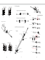
Twist the light is forbidden and correct bending way
1. Before making any cuts, installation, maintenance or connection,be sure
the mains is disconnected!
2.NOTE: ALL CONNECTOR JOINTS MUST BE CONNECTED CORRECTLY TO
ACHIEVE IP68 RATING.
3.Please operate this flex light by instructions, and confirm the work voltage,
it must be matched with product requirements
4.Please confirm the polarity of connector before insertion front connection cable.
5.Connect and cut this product correctly. Any wrong operation will damage this
product.
6.No pressing on this product during storage, long term pressing may lead to
damage.
7. Using qualified DC power supply.
8. Min. bending diameter 120mm,see Fig. 1.
9. Do not twist the light as Fig. 2 and follow the correct bending way as Fig. 3.
10.Do not hang this flex light in sky as Fig.4.
11.Cutting at wrong location will result in a failure of light! See Fig.5.
Light Surface
Light Surface
Fig . 5 Unit cutting guide
Light Surface
PCB
Light Surface
LED
PVC
×
WARNING
×
×
100mm
Cutting line
Light Surface
Light Surface
CAUTION
1. Suitable for mounting on normally flammable surfaces. .
2.Use only factory-recommended connectors and accessories.
3.To ensure its long life span, operate the light properly in accordance with the
instructions.
4.Do not operate in more than 45℃ ambient temperature.
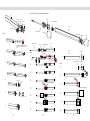
5.Assemble the Connector correctly as Fig.6.
6.Max. running length depends on the energizing way as Fig.7 shown.
7.Do not operate light when ambient temperature is below 0℃ that may injury
the light .
√
Fig . 2
√
Fig . 3
1. Turn off the electricity before operation.
2. Cutting the light at correct location ( if need).
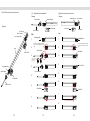
3. Assemble light according to Fig. 8,Fig. 9,Fig. 10.
4. Install U channel and light according to Fig.11.
5. Wiring all connectors to the power line and checking whole circuit wiring.
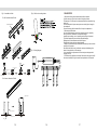
Cable color coding basics Refer to Fig. 12.
6. Applying controller to Fig.13.
×
×
Wave cutting is incorrect
ASSEMBLY AND INSTALLATION
√
√
The correct cutting way,R= 90°
Recommened Use
Fig . 4 Hang suspended installation as the picture illustrated is
forbidden
×
R=90°is incorrect
FIGURES
Fig . 6 Correct insert position of connector pins
×
Fig . 1 Minimum bent diameter 120mm
×
For 01 Type Front Connector
Light Surface
PCB
12 0 mm
Light Surface
①
②
01 Front Connector
01
Pins
3
4
5