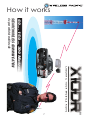
1
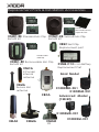
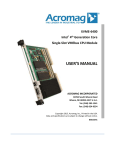
User
Manual
X10DR
®
This product is designed to radiate low
levels of radio energy in accordance with
global government approved regulatory standards. It features Adaptive Power
Output. APO automatically adjusts the RF
power output in accordance with signal
required. This features limits and reduces
extraneous radiated radio energy. This also
helps minimize battery consumption and
extends battery shift life. Do not touch the
antenna when operational. Keep Secure
Microphone antenna 10mm (2/5”) or more
away from your body to ensure exposure
levels remain at or below the maximum
levels. Keep your body at least 20cm/8”
from external antennas connected to the
X-Ponder mobile charger unit.
If you would like to review or print out a larger
version of this user manual on-line, then go to:
www.wirelesscorpltd.com
2
Table of Contents
Parts & Functions��������������������������������������������������� 4
Wearing the X10DR Secure Mic��������������������������� 5
Operation Description������������������������������������������ 6
Basic Operation���������������������������������������������������� 8
••
••
••
••
••
••
••
••
••
••
••
••
••
••
••
••
••
••
••
••
Power On & Off, Volume Control������������������ 8
Transmitting/Receiving, Emergency�������������� 8
Talk permit tone, Charging confirmation����� 9
Earpiece, Out of Range, Stealth�������������������� 9
Multiple unit operation���������������������������������� 10
Motorcycle operation����������������������������������� 11
Headset, Covert operation�������������������������� 11
Technical Notes��������������������������������������������� 12
Battery Charging������������������������������������������� 12
Replacing the battery pack������������������������ 13
Re-connection����������������������������������������������� 14
Audio adjustment������������������������������������������ 14
Antennas�������������������������������������������������������� 15
Typical Wiring Diagram �������������������������������� 16
Installation & Connections��������������������������� 17
Alternate Configurations������������������������������ 18
Replacement Parts & Accessories�������������� 27
Approvals, Warranty & Warnings����������������� 30
Important safety and handling�������������������� 32
Specifications������������������������������������������������� 37
3
X10DR
®
Nomenclature
SM = Secure Microphone
MD = X-Ponder Mobile Charger
X10DR_ _-X_1
Product Name
U = Standard Model
X = Advanced 128 Bit Model
Parts and functions
Secure
Wireless Microphone
Charging contacts
Antenna
A B
Status light
Microphone
PTT: Press-To-Talk
Loudspeaker
Manual
Antenna
Off/On
Connector
Status light
C
D
X-Ponder
Mobile Charger
DC charging
Headset connector
(Optional)
Earpiece jack
DEFAULT
A Volume down C
B Volume up D
ALTERNATE
Emergency
Off/On
A
B
Emergency
Off/On
C
D
Volume up
Volume down
Volume up: adjusts speaker audio louder.
Volume down: adjusts speaker audio softer - minimum setting.
Microphone: talk in a normal strength voice about 3 to 5cm (2”).
PTT: press to talk - 3 quick beeps when pressed*. - When out of
range the unit will sound a slow beeping tone alert.
Emergency: A quick beep sounds when pressed* and then triggers host radio’s emergency function. Hold down button as per
mobile radio’s emergency button operating instructions or as advised by your supplier - When out of range the unit will sound a
slow beeping tone alert when the button is pressed.
4
Off/On: hold for about 5 seconds to turn on or off. The Secure
mic will sound escalating or de-escalating tones to advise status.
DC charging: place into charger to automatically re-charge.
Headset connector: use with associated** headsets/accessories.
Earpiece jack: allows private listening via 3.5mm earpieces.**
Inserting the 3.5mm plug mutes the loudspeaker.
Loudspeaker: Delivers loudspeaker audio - Automatically mutes
when inserted into X-Ponder mobile charger.*
Status light: glows blue* when connected and operational.
Flashes when “out of range” or when one unit is off.
Antenna Connector: Allows connection of long range external
antenna or replacement of short range internal type.
*Normal configuration - see Installation section for alternatives. **Buy separately as needed.
Wearing the X10DR Secure Mic
X10DR is designed to best perform when worn with
the antenna protruding above your shoulder.
Different types of carry clips are available including:
Standard clip (default)
Replacement part No: XSMC
This is the traditional type allows the X10DR Secure Wireless Microphone to be clipped to work vests, clothing, epaulettes, etc.
For maximum performance 360º around your vehicle it is recommended that it be worn in a location that allows the antenna to
protrude above you body. Rare earth magnets secure the microphone in the X-ponder charging cradle.
Velcro® mount clip Replacement part No: XVMC
The Velcro mount type features a large Velcro “hook” disc on
the back of the microphone. A matching supplied Velcro “loop”
patch should be ideally sewn or pinned to the users work attire/
vest in the shoulder area to allow the antenna to protrude above
you body to ensure maximum range. Rare earth magnets secure
the microphone in the X-ponder charging cradle.
Removable clip
Replacement part No: XRMC
This type has a removable larger spring belt clip which allows the
X10DR Secure Wireless Microphone to be clipped to heavier work
vests, leather clothing, thick epaulettes, etc. It locks mechanically into the X-ponder charging cradle.
Note: Neodium, rare earth magnets, are fragile and can easily break if hit or
heavily dropped and will then need to be replaced. (Not covered by warranty) Take extra care when handling them. Keep away from credit cards or
like items, that can be damaged by strong magnetic fields.
5
X10DR
®
Operation Description
Congratulations on choosing the revolutionary X10DR®
Secure Wireless Microphone. Pronounced “extender”.
This incredibly compact, lightweight personal accessory extends the power of the mobile radio to the palm
of your hand, whether in and out of the vehicle. X10DR
stands ready to re-define mobile network design by increasing user functionality and mobility whilst dramatically improving the effectiveness of your infrastructure
investment. This visionary solution provides users out of
vehicle communications with the power and performance of their mobile radio.
X10DR cuts the cord and for the first time puts the microphone and radio system access into the palm of the
users hand when away from the vehicle, delivering true
mobility without system compromise. Users can feel totally confident their private communications are kept
secure due to the smart 64 bit/128 bit encryption (model
dependent) functionality. X10DR uniquely incorporates
HLC™ “Hard Line Coding” connection protocol that
virtually eliminates any possibility of outside intrusion between the X10DR and your vehicle’s mobile. When the
mission is critical, X10DR delivers.
X10DR unleashes the power of your mobile radio allowing wireless communication with a fixed located
or vehicle radio: 60, 150, 300 metres (yards) or more.*
Our EVR™ enhanced voice resilience audio ensures users can communicate with clean clear audio, with the
power and range of their mobile radio, whilst not being
tied to the vehicle allowing the user to be truly mobile in
every operational environment.
Finally, if you go out of range, the blue LED will flash and
the unit will sound a warning tone if you press the PTT
or Emergency button so you know to move back into
your communication zone or to be simply aware. This
ability to now communicate whilst outside your vehicle
significantly enhances a safer and more secure work
environment for everyone who carries an X10DR Secure
Wireless Microphone.
6
How it works
60.... 150.... 300 Metres.
SECURE WIRELESS COMMUNICATION
via your vehicle’s mobile radio
7
X10DR
®
Basic Operation
Power On & Off
Usually the unit will be installed such that it powers off & on with
the host mobile radio or by a manual switch fitted by your installation mechanic. You can manually turn off the X-Ponder mobile
charger by pressing the front grey button for 3 seconds and the
blue LED will extinguish. You can do the same on the Secure Wireless Microphone by pressing the grey button. The secure mic will
sound a de-escalating tone. To power On, do the same, releasing the button once the LED lights. The secure mic will sound an
escalating tone. The blue LED on both units will flash momentarily
and then go solid once they’re connected.
Volume Control
When you first activate the unit you should first ensure your mobile
radio’s volume is set to a comfortable listening level. You may
then adjust the Secure Wireless Microphone volume by pressing
the right top button to increase or the left to decrease. There are
5 listening levels. The minimum level is not zero but is designed so
you can still quietly hear radio traffic and not inadvertently turn
off the audio.
Transmitting/Receiving
Use like any two way radio speaker Mic i.e. press the large black
PTT button to talk and release to listen. A short Talk permit tone sequence will sound. Speak with a normal strong clear voice about
3-5cm (2”) from the microphone port. Do not yell as this causes
loss of clarity.
Out of Range Indication
X10DR provides the user with audible feedback should the user
move out of range from their vehicle. Note: if you walk out of
range the blue status LED will flash. If you then push the PTT an alert
tone will sound to let you know your call is not getting though.
Pressing the Emergency button when Out of Range will provide a
similar indication. Depending on your location, you may find you
need to walk back about 10 meters (yards) closer to your vehicle
to re-connect - Blue status light will then glow solid.
8
Talk Permit tone
X10DR provides talk permit tones so users know when to start
speaking so that words are not lost at the start of a transmission.
If, the channel is busy, no channel grant or you are out of range,
the user will hear the X10DR talk permit tones followed by the
radio BUSY or Out of Range tone. (can be disabled by field programmer)
Charging Confirmation Tone
X10DR provides the user with a discrete tone whenever the X10DR
Secure Mic is returned to the charging cradle. This discrete chirp
ensures the user has a positive indication that the X10DR Secure
Mic is charging and seated correctly in the cradle.
Earpiece Operation
X10DR provides the user with a weather protected 3.5mm earpiece jack to allow use of industry standard earpieces thereby
providing additional privacy of communications. A range of earpiece styles are available to suit individual user preferences. Plugging in an earpiece disables the internal loudspeaker.
Emergency
If enabled, the emergency button can be used to trigger and
reset the emergency function in your suitably equipped mobile radio. The time you hold the button is the time your mobile
radio sees the emergency command. So if your radio requires
you to hold the front panel emergency button for 2 secs, then
you should hold the Wireless Microphone emergency button for
2 seconds. When you press the emergency (orange) button a
short beep will sound. (Can be disabled by use of X10DR Field
programmer) See page 22 for other Emergency operations information.
Stealth Mode
For special applications the secure Mic’s Blue LED on the front of
the Secure Mic can be temporarily disabled. This is achieved by
holding down the VOLUME UP/DOWN (both) while powering up
the unit. To turn the LED back on, simply power down and power
back up. The feature may be of particular use to“Law Enforcement Users” who may prefer in some situations to not be walking
around at night with a blue light glowing on their shoulder.
9
X10DR
®
Multiple Unit Operation
Multiple X10DR Secure Wireless Microphones with EVR™ enhanced audio may be connected to one radio device by use of
the optional XIB Interface box accessory. Operation is identical
to single user operation with the added benefit that, each party
also hears each other talk when they transmit. This functionality
is ideal for police: where two officers are assigned to a patrol
van, or ambulance: where 3 paramedics can communicate at
a scene as well as with their control room. It is also ideal for office
use allowing a number of personnel to access a local base or
control station or remote control console while moving around a
building, shop or warehouse.
Note: communication between X10DR users is always routed
back through their respective X-ponder mobile chargers and not
direct between units. Ask your dealer for more information on this
unique and highly regarded operational capability.
INSTALLERS NOTE:
Use of the XBDA “booster” accessory is NOT compatible with
multiple unit installations. Multiple unit operation requires that antennas are located ideally >50cm (20”) apart to minimize the opportunity for cross unit interference. Attention needs to be made
when locating antennas so that each X10DR provide similar coverage patterns to ensure balanced unit to unit communications.
Motorcycle Operation
The X10DR Secure Wireless Microphone is especially suitable for
motorcycle use. Models fitted with a 6 pin Hirose industrial connector allow easy connection to a helmet microphone and dual
earpiece fit out. Making use of the handlebar PTT input, a bike
can be configured so that, when the rider is on the bike and
presses the handle bar PTT, their headset microphone audio is
sent out over the radio. Off the bike but still wearing the helmet,
the user can press the Secure Wireless Microphone PTT to talk,.
Finally, if the user removes their helmet, they can unplug from the
Hirose connector on the base of the unit and just use the Secure
Wireless Microphone like standard.
10
Headset Operation
The 6 pin Hirose industrial connector also allows use of a variety
of heavy duty and lightweight headsets and application specific
audio accessories to enhance you communications capability. Use either the headset/accessory’s integral PTT or use the
speaker mic PTT to transmit. The internal speaker is immediately
disabled when a headset is plugged in.
Accessory Mic Boost
Users can increase an audio accessory’s microphone gain on
X10DR models fitted with the Hirose accessory port to cater for
sensitivity requirements or variations in headset manufacturer’s
specifications. To activate the higher sensitivity, the X10DR’s blue
VOLUME UP button should be held down while powering up. The
user will thereafter hear 2 short confirmation beeps at the end of
each start up tone sequence. To revert to standard operation,
the unit should be powered up with the VOLUME DOWN blue button held down.
NOTE: this does NOT effect the sensitivity of the X10DR’s normal
internal front cover microphone.
N.B. See page 36 for safety warning regarding use of headsets.
Covert Operation
The small size of the X10DR unit may allow for its selective use
in covert applications. The remote monitor PTT function means
someone else can enable “listening” without the covert operative having to touch anything. As audio is duplex (bidirectional)
you can also talk to them at the same time allowing vital messages to be passed on even when an operative is transmitting.
The advanced model : X10DR-XX1 unit provides 128 bit encryption version to ensure high levels of voice security, while the
standard X10DR-XU1 versions provide 64 bit encryption. Both encryption types are based on the well recognized highly secure
‘SAFER” format.
11
X10DR
®
Technical Notes
Battery - Charging
The X10DR Secure Wireless Microphone
should be charged overnight before
initial use. Thereafter it may be left in the
charger unit between calls, or may be
worn all day and placed back at the
end of the work day. The unit is designed
to provide about 12 hours operation between charges even on the busiest radio
channels. On quiet channels it can last
up to 3 days. When the battery does start
to go flat, a short beep will sound once
every 2 minutes. It will then automatically
power down after 30 minutes, so you
should plan to re-charge the unit as soon
as is practical once the chirps are heard.
A fully discharged battery will typically recharge in less than 4 hours, or less if only
partially discharged. The battery will recharge even if the mobile charger unit
has been turned off. The microphone’s
blue status light will indicate charging
mode.
Simply place into pocket. The X10DR
will beep to show correct placement.
NB: do not allow debris to fill the pocket
as it may prevent the microphone from
making contact with the charging pins
Keep all liquids well away from the
charging cradle at all times.
12
Li-POL
Please recycle thoughtfully
Replacing the battery pack
When you notice the X10DR sounding a small chirp,
it indicates the battery is nearly flat and should be recharged. The unit will self power down after 30 minutes
when voltage drops to that level. When you notice this
occurring far more often than usual, it may mean it is
time for the battery to be replaced.
Like all re-chargeable products, periodic replacement
of the internal battery is required. The Secure Wireless
Microphone features a 1200mA Lithium Polymer battery
to provide typically well over 12 hours operation when
used on a busy radio channel.
To maximize the life of a Lithium battery its is better to
keep it topped up by returning it to the charger often
rather than waiting for it to first go flat - which was the
opposite case with older nickel based batteries. Typically you can expect to get about 500 plus full re-charge
cycles before the battery will require replacement.
The process is simple and should only take your radio
service supplier about 5 minutes to replace and test.
Replacement of the battery should be ONLY undertaken by a qualified service technician so as to ensure no
damage occurs to internal circuitry and to ensure the
housing’s weatherproof integrity is not compromised.
The replacement battery part number is: XSMB-C12:
1200mA Li-Ion battery.
After replacement, the Secure Wireless Microphone
must be first placed back into the mobile charger and
will initially should be charged for 8-10 hours prior to
commencement of use. Depending on the situation
it may also need to be “re-connected” to the mobile
charging unit)
13
X10DR
®
Re-connection
Each X10DR Secure Wireless Microphone is uniquely
connected to a specific X-Ponder mobile charger. This
ensures that all communications between the two units
are secure and cannot be compromised or interfered
with by a third party. In the event of a Secure Wireless
Microphone being lost, it can be permanently disconnected from the X-Ponder mobile charger by connecting with a new replacement Secure Mic unit.
How to re-connect: hold the speaker mic while pressing
both the blue up and down volume controls until the
blue LED flashes and the speaker mic beeps.(after 8 secs.)
Now place the speaker mic back
Press blue buttons
into the mobile charger. After a few
together until LED
flashes and unit
seconds the speaker mic will sound a
beeps
confirmation two tone and the blue
LED on both units will glow solid to indicate connection is complete.
Audio adjustments
Qualified service personnel only!
The Secure Wireless Microphone system is usually factory set for standard
audio levels required to provide satisfactory mobile radio voice levels.
Should the volume be too soft or
loud and distorted, it may require re- VR1
adjustment to set the correct level - Tx
for your particular installation.
VR2 - Rx
Using a radio systems analyser to monitor the radio
channel adjust the internal trim pots so as to achieve
maximum permitted voice deviation within minimum
voice clipping (distortion). See Page 16 for adjustment points.
14
Antennas
As compared to the basic internal 1/4 wave stub antenna, the XMMA magnetic mount antenna provides
enhanced coverage when placed on an unobstructed
area of a vehicle’s roof and should be connected via
its low loss coax cable to the RP-SMA-F output on the
mobile charger. MAKE SURE YOU FULLY TIGHTEN!
The XMAK multipolarity antenna provides even greater
coverage in multipath - non line of sight - situations. It
should be bracket mounted onto an unobstructed area
above the vehicle’s roof line and should be connected
via the supplied low loss coax cable to the RP-SMA-F
output connector. MAKE SURE YOU FULLY TIGHTEN!
Alternatively, where approved, the XBDA bidirectional
amplifier may also be installed to further enhance inbuilding coverage from your vehicle. The XBDA is installed in series between the antenna and the mobile
charger using a 20cm (8”) length of RG174 coax cable
and a 5M (17’) length of LMR200 coax to ensure a maximum of 1W output to the antenna. Only qualified radio
service personnel should install a XBDA so as to ensure
the effective radiation level remain in full compliance
with regulatory requirements in your country of operation.
Keep your body at least 20cm (8”) away
from vehicle mounted external antenna.
See page 32 for other important details.
Warning:
In the event of a damaged or lost antenna, only original
replacements should be used so as to not compromise
the units type approval certification or performance.
The speaker microphone uses a unity gain ground independent antenna for maximum multi-directional range.
The mobile charger output has a reverse polarity SMA
female antenna connector, as does the XBDA.
15
X10DR
®
16
Installation & Connections
1. Switched B+: Used to automatically turn on/off Secure Wireless Microphone if connected to host radio
switched B+ output, if not, the user should supply manual on/off switch. Note: internal speaker microphone
battery will still charge when the unit is turned off.
2. External Mic Audio: Audio from the Wireless Microphone that is to be transmitted over the host mobile
radios transmitter. It is factory set for approx 80mV RMS.
3. Radio Mic Lo: This is microphone audio ground.
4. Receive Audio: Receive audio from the host mobile
radio that you wish to be sent to the Wireless Microphone. Ideally, it should be sourced pre-volume control but can be post, as long as the host mobile radio’s
speaker audio has been sent for comfortable listening
in the vehicle.
5. Power: connected via a 1 amp in-line fuse preferably
direct to a vehicle’s 12V battery but can be any voltage from about 6-16VDC. Current consumption is typically 60mA/Max current 420mA@6V. (12V = <200mA)
6. Ext. PTT: Switched ground output designed to cause
the host mobile radio to transmit.
7. Emergency: Output intended to connect to the host
mobile radio’s emergency input. It is normally provides
an active switched ground but can be configured to
be active open circuit. The time held low (or high) is the
exact time that the user presses the Emergency button.
This output could be used for other functions such as to
trigger the panic function of a car alarm system, providing it is correctly “buffered” so as to not cause damage
to the mobile charger.
8. COR/squelch/audio unmute: Input designed to monitor the receive status of the host mobile radio. Ideally, it
is driven by an “audio unmute” switched ground command in the host mobile. i.e. when the radio’s speaker
unmutes to pass audio then the COR input should toggle in sync.
17
X10DR
®
Alternatively, it could be driven by the radio’s unsquelch command that factors in reception of required
correct CTCSS tones, etc. An internal dip switch caters
for active low or high inputs.
9. Ground: DC /Digital ground connection.
13. Remote PTT: This provides a remote alternative to
transmit secure microphone audio via the host mobile radio. You may choose to connect to a motorbike
handle bar PTT, a hidden palm or footswitch, a wireless
PTT device, or even to an output from the host mobile
equipped to provide remote radio monitoring of the secure microphones users audio. In such remote monitoring cases, use of the remote PTT input causes the sensitivity of the INTERNAL secure microphone to be greatly
increased, so a control room operator can more easily
monitor the health or safety of the user. There is no increased audio gain when a headset is connected to
the audio port at the base of the secure microphone.
Alternate Configurations
Some alternate configurations are available by use of
the internal dip switches in the X-Ponder mobile charger
unit. These are provided to allow compatibility with different mobile radio types.
Re-configuration of these switches should only be
undertaken by qualified radio service personnel.
To access, first remove the rear mounting plate from
the mobile charger. Next remove the 4 case screws to
access internal PCB. Take extreme care when handling
the PCB to prevent damage by electrostatic discharge
(ESD) or to internal wiring. Re-assemble carefully.
18
Mobile Charger PCB layout
Installation dip switch configuration:
- For N/C emergency trigger:
Sw1 On Sw2 Off (default)
- For N/O emergency trigger:
Sw1 OFF Sw2 ON
- For active low radio COR
Sw3 OFF (default)
- For active high radio COR
Sw3 ON
- For Vox enable Sw4 ON(default)
- For Vox disable* Sw4 OFF
- Speaker disable in cradle
Sw6 ON(default)
- Speaker enable in cradle
Sw6 OFF#
R40 Default: not fitted - Fit 0 ohm** for DC shift COR detect
R41 Default: fitted
- Remove for DC shift COR detect
** or as appropriate
# Prevents the secure mic from muting when placed inside a
charger. This option is generally recommended only when the
host radio has no internal or external speaker.
Note: may cause the re-charge time to increase significantly on
a very busy radio channel.
19
X10DR
®
Multiple Units
XIB Interface Box
The XIB allows multiple X10DR’s to be connected to the one mobile radio.
X10DR units can hear each others communications as well as conversations
over the network. The interface unit connects to the host radio via a XMC
series interface cable.
Each X10DR connects to the XIB by way of short 50cm (20”) XIB-CK connecting
cables. Note: Antenna placement is critical and should be ideally placed >50cm
(20”) from each other to minimize inter-unit interference. This unit is designed
to cross–connect two/three X10DR units to one host radio. The radio connects
to the RADIO port on the XIB. Units can be cascaded to allow connection of
more than three X10DRs to the one mobile.
ALIGNMENT: Before setting up the interface box, first connect each X10DR
directly one at a time to the host radio and carefully adjust VR1 & VR2 trimpots
as described on page 14. After this the X10DR units are ready to be connected
to the interface box. Next, talk on the 1st X10DR and listen to the sound coming
from the 2nd X10DR. Then talk on the 2nd X10DR and compare sound coming
from the 1st X10DR. Adjust the MAIN IN and 2ND IN trimpots so each X10DR
has the same loudness. Next, talk on the 1st X10DR and compare the host
radio transmit audio quality compared with the host radio fist microphone by
listening or another radio. If necessary adjust the RADIO OUT trimpot to match.
Finally, talk on the other radio and adjust the RADIO IN trimpot so that the received audio on the X10DR is loud and clear, but not distorted, and matches the
audio level when talking on the other X10DR. Repeat if a third X10DR is fitted.
Note: Incorrect level settings may cause distortion or noisy audio, especially
on some digital radios.
20
Lone Worker
XFB-LW Lone Worker Function Box
The XFB-LW provides “lone worker” functionality to the X10DR. Dip switches
allow custom parameter setting for activity time interval (time in which a user
must momentary press their PTT), as well as the user prealert tone interval (period where the X10DR user hears a warning tone that an emergency condition
is imminent). Pressing the PTT will reset the imminent emergency condition.
Additionally, a 10 Sec Live Mic feature can also be selected. The XFB-LW connects to the host radio via an XMC series interface cable. The X10DR connects
to the XFB-LW by a XIB-CK connecting cable.
ALIGNMENT: First preset the XFB-LW DIP switches (see Pg 24). Before setting
up the XFB-MR, first connect the X10DR directly to the host radio and carefully
adjust VR1 & VR2 trimpots as described on page 14. Now the X10DR can be
connected to the XFB-LW. Next, talk on the X10DR and listen on another radio
to the transmit and receive audio coming from the host radio. Adjust Radio IN
if necessary so that audio levels again match the radio’s fist mic. Now adjust
Radio OUT to make sure X10DR speaker audio is loud and clear.
XFB-DP Function Box
1 x XFB-DP
1 x XMC-***
1 x XIB-CK
The XFB-DP allows dual functionality of the orange side button.
A short (<0.5 Sec) can provide a unique switched ground to a
connected mobile I/O port, while a 3 second press can be used
to drive the radio’s emergency input or other desired function.
Other functions include:
i/ 145 or 300 mSec Rx audio digital delay - Dip switch selectable.
ii/ DB15 port with local on/off & emergency input/outputs.
ALIGNMENT: First preset the XFB-DP DIP switches (see Pg 20).
Use the same alignment procedure as for the XFB-LW above.
21
X10DR
®
Talkaround with Emergency
1 x XFB-TA
1 x XMC-***
2 x XIB-CK
XFB-TA Talk-Around Function Box
The XFB-TA allows two/ X10DR to have local (talkaround) operation where users can talk locally “off net” by using the orange side button as a secondary
PTT. To talk over the radio channel, the normal PTT button is used. Individual
trimpots on the module allow the audio levels to be matched across both
X10DRs and the host radio. To activate Emergency, the user must first press
the PTT and then the orange button for >1 second. The XFB connects to the
host radio via a XMC series interface cable. Each X10DR connects to the XFBTA via a XIB-CK cable.
ALIGNMENT: First preset the XFB-TA DIP switches (see Pg 26). Next, connect
each X10DR, one at a time, directly to the host radio and adjust carefully VR1
& VR2 trimpots as described on page 14. After this the X10DRs are ready to
be connected to the XFB-TA. Now talk on the Main X10DR and listen to the
sound coming from the 2ND X10DR. Then talk on the 2nd X10DR and compare
sound coming from the Main X10DR. If necessary, adjust the MAIN IN and 2ND
IN trimpots so that each X10DR has the same volume. Next, talk on the Main
X10DR and listen on another radio to compare the host radio’s transmit audio
quality and loudness when compared with its fist microphone. Adjust the RADIO OUT trimpot to match. Finally, talk on another radio and adjust the RADIO
IN trimpot so that the received audio on the X10DR’s are loud but not distorted,
and match the audio levels when talking on the other X10DRs.
Multiple Radios
Public Address
22
XFB-MR Multi-Radio Function Box
The XFB-MR allows 2 mobile radios to be connected to the one X10DR unit. A
unique marker tone* is attached to the tail of each secondary radio reception
to inform users which radio’s audio they just heard. A marker tone* trimpot is
provided to allow the tone level to be set to the users desired listening level.
The XFB unit can be configured to either maintain the secure microphone’s
normal emergency functionality with PTT only possible on RADIO 1, or alternatively, to use the orange button to transmit on the secondary channel. In
which case, the user must then first press the PTT and then the orange button
for >1 second to activate emergency. The X10DR connects to the XFB-MR by a
XIB-CK connecting cable and the radios via two XMC series interface cables.
ALIGNMENT: First preset the XFB-MR DIP switches (see Pg 26). Begin by connecting the X10DR directly to the first radio and carefully adjust VR1 & VR2
trimpots as described on page 14. The X10DR can then be connected to the
XFB-MR. Next, talk on the X10DR and listen on another radio to the transmit
and receive audio on the 1st radio. If necessary adjust Radio 1 IN so that audio
levels again match the radio’s fist mic and adjust Radio 1 OUT to ensure the
X10DR’s speaker audio is loud and clear. Talk on the 2nd radio (use orange button) and compare sound levels with the 1st radio. Adjust the RADIO 2 IN trimpot
so each transmission has identical volume. Next, talk on the X10DR and listen
(via another radio) to the transmit and receive audio coming from the 2nd radio.
Adjust Radio 2 IN so that it matches the 2nd radio’s fist mic before adjusting
Radio 2 OUT for optimum X10DR speaker audio volume and clarity. Finally, adjust the TONE trimpot to set the marker tone* to a useful but not annoying level.
Public Address Function
Alternatively, the XFB-MR second port can be attached to the vehicle’s Public Address system to allow the user to talk over the vehicle’s public address
system by simply pressing the orange button X10DR microphone. To activate
emergency the user must first press the PTT and then the orange button for
>1 second. The X10DR connects to the XFB via a XIB-CK connecting cable.
The XFB unit then connects to the host radio via a model specific XMC series interface cable. Connection to the vehicle’s public address system is via a
XMC-GEN cable connected to the RADIO 2 port. The installer should connect
the PA enable to Pin 6 of the X10DR interface and the PA mic input should
connect to Pin 2.
ALIGNMENT: First preset the XFB-MR DIP switches (see Pg 26). Adjust RADIO
1 levels as above. PA audio level out can be set via adjusting the IN trimpot on
the RADIO 2 port.
* Not compatible with radios that cannot provide a COR/TOR/spk unmute indicate, etc. input.
23
X10DR
®
XFB DIP Switch Settings
XFB-LW DIP SWITCH SETTINGS
1
1
2
2
3
3
4
4
5
5
6
6
7
7
8
8
UP
DN
UP
DN
UP
DN
UP
DN
UP
DN
UP
DN
UP
DN
UP
DN
Audio delay disabled
Audio delay enabled*
Direct audio disabled
Direct audio enabled*
Audio delay time = 260mS
Audio delay time = 145mS
Ungated radio rx audio
Gated radio rx audio
Lone alert time MSB off
Lone alert time MSB on
Lone alert time LSB off
Lone alert time LSB on
Live mic disabled
Live mic enabled
Radio COR active low
Radio COR active high
*Emergency function triggered by holding buttons for 1 second.
XFB-TA DIP SWITCH SETTINGS
1
1
2
2
3
3
4
4
5
5
6
6
7
7
8
8
UP X10DR PTT triggers PTT on Radio 1 & Radio 2.
DN X10DR PTT triggers PTT on Radio 1 only.
UP X10DR orange button triggers emerg. function* (selectable by options below).
DN X10DR orange button PTT on Radio 2 only.
Trigger emergency by first pressing PTT and
then orange buttons together*.
UP Radio 1 emergency function off.
DN Radio 1 emergency function on.
UP Radio 2 emergency function off.
DN Radio 2 emergency function on.
UP Radio 1 emergency function active ground (NO).
DN Radio 1 emergency function active open circuit (NC).
UP Radio 2 emergency function active ground (NO).
DN Radio 2 emergency function active open circuit (NC).
UP No live mic for emergency function.
DN 10 second live mic for emergency function.
UP Early X10DR models
DN Later X10DR models
*Emergency function triggered by holding buttons for 1 second.
24
NB: Each XFB model has different firm/hardware
XFB-DP DIP SWITCH SETTINGS
1
1
2
2
3
3
4
4
5
5
6
6
7
7
8
8
UP
DN
UP
DN
UP
DN
UP
DN
UP
DN
UP
DN
UP
DN
UP
DN
Audio delay disabled
Audio delay enabled*
Direct audio disabled
Direct audio enabled*
Audio delay time = 260mS
Audio delay time = 145mS
Ungated radio rx audio
Gated radio rx audio
N/A
N/A
N/A
N/A
Dual function disabled
Dual function enabled
Radio COR active low
Radio COR active high
*Emergency function triggered by holding buttons for 1 second.
XFB-MR DIP SWITCH SETTINGS
1
1
2
2
3
3
4
4
5
5
6
6
7
7
8
8
UP X10DR PTT triggers PTT on Radio 1 & Radio 2.
DN X10DR PTT triggers PTT on Radio 1 only.
UP X10DR orange button triggers emerg. function* (selectable by options below).
DN X10DR orange button PTT on Radio 2 only.
Trigger emergency by first pressing PTT and
then orange buttons together*.
UP Radio 1 emergency function off.
DN Radio 1 emergency function on.
UP Radio 2 emergency function off.
DN Radio 2 emergency function on.
UP Radio 1 emergency function active ground (NO).
DN Radio 1 emergency function active open circuit (NC).
UP Radio 2 emergency function active ground (NO).
DN Radio 2 emergency function active open circuit (NC).
UP No live mic for emergency function.
DN 10 second live mic for emergency function.
UP Early X10DR models
DN Later X10DR models
*Emergency function triggered by holding buttons for 1 second.
25
X10DR
®
WPEB/TL
WPiTRQ-X10
WPEH/TL
WPTEP/TL
WPLWH-X10
X10DRDC
Desktop Charger
WPSHD
WPSHC-HIR
XFB
WPSHC-NEX
WPWLP-HIR
XIB
26
XMC-* Series
XIB-CK
Audio & General Accessories
The following antenna accessories are available from your X10DR
Secure Wireless Microphone supplier:
X10DRDC-* - Desktop 3-4 hour charger includes AC/DC
plug pack for X10DR Secure Microphone.
*specify AC plug: US(2P), UK, EU(2P), AU.
WPLWH-X10 - Lightweight headset, noise cancelling type
with in-line PTT & Hirose 6 pin connector.
WPSHD - heavy duty headset, noise cancelling type
with on cup PTT & volume control.
(requires one of the following cables)
WPSHC-HIR - WPSHD to Hirose Interface curly cable
WPSHC-NEX - WPSHD cable with 4P Nexus connector
(for use with WPWLP-HIR)
WPWLP-HIR - In-line PTT cable with Hirose connector
and wireless finger PTT button.
(also use with Peltor series headsets)
WPEH - Large black “across ear” earpiece.
WPTEP - Acoustic tube “quick disconnect”
- Black ear bud “in-ear style”
WPEB (above 3 for use with 3.5mm jack on Secure Mic)
WPiTRQ-X10 - Advanced ear lapel mic with Hirose con
(requires following TL series earpiece)
WPEH-TL
- Large black “across ear” earpiece for iTRQ.
WPTEP-TL
- Acoustic tube “quick disconnect” for iTRQ.
WPEB-TL
- Black ear bud “in ear style” for iTRQ.
XIB XFB-**
XMC-**
XMC-3M
XIB-CK
-2/3 way interface box.
(Requires XIB-CK for each X10DR.)
- Special function box.
(**different types available-Requires XIB-CK cable)
- Interface cable, 1.5m (5’) length.
(**different models available)
- Interface extension cable, 3m (10’) length.
- X10DR to XIB/XFB cable, 50cm(20”) length.
27
X10DR
®
Replacement Parts & Installation Accessories
Includes labels
magnet & screw
Includes labels
Velcro hook (sow on)
magnet & screw
XSMC-RK Standard Mic Clip XVMC-RK Velcro® Mic Clip
Retrofit kit
Retrofit kit
XRBC Belt Clip
Replacement part
Includes labels
& belt clip
XRMC-RK Removeable Mic Clip
XSMB-C12 Li Ion Battery
Replacement Part
Retrofit kit
XMCA
X-Ponder
internal
antenna
Basic Model
XSMA
Secure Mic
antenna
X10DRMD-XU1
X10DRSM-XU1
XBDA
Advanced Model
(128 Bit)
X10DRMD-XX1
XMAK
XMMA
XMDM
28
X10DRSM-XX1
XSMC-RF - Spring clip back cover retrofit kit.
XVMC-RF - Velcro mount back cover retrofit kit.
XRMC-RF
XRBC
- Removable clip back cover retrofit kit.
- Spare removable belt clip for XRMC.
XSMA
XMCA - Antenna for Secure Mic or XMMA.
- Internal antenna for X-Ponder charger.
XSMB-C12
- 1200mA Li-Ion battery for Secure Mic.
X10DRSM-XU1 - Replacement basic secure mic.
* order with XHC if Hirose conn.required.
X10DRMD-XU1- Replacement basic mobile charger.
(X-Ponder)
X10DRSM-XX1 - Replacement 128Bit secure mic.
X10DRMD-XX1- Replacement 128Bit mobile charger.
(X-Ponder)
XMAK - Unity gain, bracket mount, multi-polarity
antenna kit with 5m (17’) low loss LMR200
(equivalent) coax and fitted RP SMA-M
and unfitted N-type F connector.
XMMA - Unity gain magnetic mount 1/4 wave
ground independent antenna kit with
3.5m (12’) low loss LMR200 (equivalent) coax and fitted RP SMA-M connector.
XBDA - 1W Tx /9dB Rx gain bidirectional amp
with 20cm/8” RG174 coax tail & 1m/39”
power cable. (Available only where approved)
XMDM - Mobile X-Ponder multi-position vehicle
mount bracket.
29
X10DR
®
Type Acceptance
RADIO AND TELEVISION INTERFERENCE
The equipment described in this manual generates, uses, and radiates radiofrequency energy. If it is not installed and used correctly—it may cause interference with radio and television reception.
CE DECLARATION
This equipment has been tested and found to comply with the following harmonised European Norms:
•EN300328 (radio and telecommunications terminal equipment)
•EN55024 (electromagnetic immunity) •EN55022 Class B (electromagnetic
emissions) •EN 60950 (electrical safety) •EN301489 (electromagnetic compatibility and radio spectrum matters) Based on the results of these tests, Wireless
Corporation declares that the above mentioned devices conform to Article
10.1 of the European Council Directive 89/336/EEC, and their amendment
Directive 93/68/EEC, and to the Directive 1999/5/EC and indicates this conformity by the CE-sign on each device. The device must be installed and operated in strict accordance with the instructions given in this user manual. Any
changes or modifications to this product that were not specifically authorised
will invalidate this declaration.
FCC NOTICE
This equipment complies with Part 15 of the FCC Rules. Operation is subject to
the following two conditions: (1) this device may not cause harmful interference, and (2) this device must accept any interference received, including
interference that may cause undesired operation.
This equipment has been tested and found to comply with the limits for a Class
B digital device, pursuant to Part 15 of FCC Rules. These limits are designed to
provide reasonable protection against harmful interference in a residential
installation. This equipment generates, uses and can radiate radio frequency
energy and, if not installed and used in accordance with the instructions, may
cause harmful interference to radio communications. However, there is no
guarantee that interference will not occur in a particular installation.
You can determine whether the equipment is causing interference by disconnecting power. If the interference stops, it was probably caused by the
equipment. If the equipment does cause interference to radio or television
reception, you may be able to correct the interference by using one or more
of the following measures:
•Rotate the television or radio’s antenna until the interference stops.
•Move the Wireless Microphone farther away from the television or radio.
If necessary, consult your two way radio dealer or an experienced radio/
television technician for help. Changes or modifications to this product not
authorized by Wireless Corporation Ltd could void the FCC Certification and
negate your authority to operate the product.
Notice : Changes or modifications not expressly approved by the party for
compliance could void the user’s authority to operate the equipment.
IMPORTANT NOTE:
To comply with the FCC RF exposure compliance requirements, no change
to the antenna or the device is permitted. Any change to the antenna or the
device could result in the device exceeding the RF exposure requirements
and void user’s authority to operate the device.
30
INDUSTRY CANADA:
This device complies with Industry Canada licence-exempt RSS standard(s).
Operation is subject to the following two conditions: (1) this device may not
cause interference, and (2) this device must accept any interference, including interference that may cause undesired operation of the device.
Le présent appareil est conforme aux CNR d’Industrie Canada applicables
aux appareils radio exempts de licence. L’exploitation est autorisée aux deux
conditions suivantes : (1) l’appareil ne doit pas produire de brouillage, et (2)
l’utilisateur de l’appareil doit accepter tout brouillage radioélectrique subi,
même si le brouillage est susceptible d’en compromettre le fonctionnement.
Warranty
Wireless Corporation Ltd (WCL) warrants each new product sold by WCL to be
free from defects in material and workmanship under normal use and service.
The obligation and liability of WCL under this warranty is limited to the repair or
replacement at its factory, at the option of WCL, of any such product which
proves defective within the quoted warranty period, twelve (12) months for
Wireless Pacific products after delivery, and is found to be defective in material and workmanship by WCL inspection. Products of warranty consideration shall be returned with all transportation charges prepaid to WCL or our
nominated local service supplier in shipping containers which are adequate
to prevent loss or damage in shipment. WCL will pay the return carriage costs
for Wireless Pacific products. Products repaired or replaced under this warranty are warranted for the unexpired portion of the original warranty. This
warranty is invalid if the factory-applied serial number, date code label, or
product label has been altered or removed from this product . WCL shall not
be obligated or liable under the warranty for apparent defects which examination discloses are due to tampering, misuse, neglect, improper storage, acts
of nature, physical abuse, normal wear and all cases where the products are
disassembled by other than authorised WCL representatives. In addition, WCL
shall not be obligated or liable under this warranty unless the date of delivery
to the first end user shall be within one (1) month from the date of delivery to
the original purchaser, if different from the first end user, and further provided
that written notice of any defect shall be given to WCL within thirty (30) days
from the date such defect is first discovered. In no event will WCL accept
consequential damages for products supplied and are then found to have
become defective.
Repairing or Modifying X10DR:
Never attempt to repair or modify X10DR yourself. X10DR does not contain
any user-serviceable parts, Disassembling an X10DR, including the removal
of external screws and back cover, may cause damage that is not covered
under the warranty. If an X10DR has been submerged in water, punctured, or
subjected to a severe fall, do not use it until you take it to an WCL Authorized
Service Provider. Service should only be provided by WCL or an WCL Authorized Service Provider. If you have questions or for service information, contact
WCL or an WCL Authorized Service Provider.
31
X10DR
®
Important Safety and Handling Information
To avoid injury, read all operating instructions and the following safety information before using X10DR. For downloadable versions of the latest X10DR User
Guide, visit: www.wirelesscorpltd.com
WARNING: Failure to follow these safety instructions could result in
fire, electric shock, or other injury or damage to X10DR or other property. Read all safety instructions for any products and accessories
before using with X10DR. WCL is not responsible for the operation of,
or any damage caused by, third-party accessories or their compliance with safety and regulatory standards.
Radio Frequency Interference:
Radio frequency emissions from electronic equipment can negatively affect
the operation of other electronic equipment, causing them to malfunction.
Although X10DR is designed, tested and manufactured to comply with regulations governing radio frequency emission in countries such as the United
States, Canada, the European Union, and Japan, the wireless transmitters
and electrical circuits in the X10DR may cause interference in other electronic
equipment. Therefore, please take the following precautions:
i/Aircraft: Use of X10DR may be prohibited while travelling in aircraft.
ii/Vehicles: radio frequency emissions from X10DR may affect electronic systems in motor vehicles. Check with the manufacturer or its representative regarding your vehicle.
iii/Pacemakers: The Health Industry Manufacturers Association recommends
that a minimum separation of 15 cm (6 inches) be maintained between a
handheld wireless phone and a pacemaker to avoid potential interference
with the pacemaker. Persons with pacemakers:
•
•
•
•
•
Should always keep X10DR more than 15 cm (6 inches) from
the pacemaker when turned on.
Should not carry X10DR in a breast pocket.
Should use the ear opposite the pacemaker to minimize the
potential
for interference If you have any reason to suspect that interference is taking place, turn X10DR off immediately.
X10DR may interfere with some hearing aids. If you experience
interference, consult the hearing aid manufacturer or your
physician for alternatives or remedies.
v/ Other Medical Devices: If you use any other personal medical device, consult the device manufacturer or your physician to determine if it is adequately
shielded from radio frequency emissions from X10DR.
vi/Health Care Facilities: Hospitals and health care facilities may use equipment that is particularly sensitive to external radio frequency emissions. Turn
X10DR off when staff or posted signs instruct you to do so.
vii/Blasting Areas and Posted Facilities: To avoid interfering with blasting operations, turn off the X10DR when in a “blasting area” or in areas posted “Turn off
two-way radio.” Obey all signs and instructions.
32
Exposure to Radio Frequency Energy:
The unit transmits and receives radio frequency (RF) energy through its antennas. The antennas are located at the top edge of the unit. The Wireless
Speaker Microphone is designed and manufactured to comply with the limits
for exposure to RF energy set by international regulatory agencies, including
the FCC of the United States, IC of Canada, MIC of Japan, and the Counsel
of the European Union, among others. The unit has been tested and meets
the FCC, IC, and European Union RF exposure guidelines for 802.15 operation. To ensure exposure levels remain at or below the maximum safe levels,
when carrying the unit ONLY use the Wireless Speaker Microphone with the
manufacturer’s supplied clothing clip or a non-metalic holder that ensures the
antenna remains greater than 10mm (2/5 inch) from your body at all times. An
external antenna is connected to the output connector on the mobile charger or to the output connector on the XBDA bidirectional amplifier. Always keep
your body at least 20cm (8”) from the vehicle mounted external antenna. The
XBDA is only approved for use with the X-Ponder unit when in accordance with
individual country type approval regulations.
Potentially Explosive Atmospheres:
Turn off X10DR when in any area with a potentially explosive atmosphere. Do
not charge X10DR, and obey all signs and instructions. Sparks in such areas
could cause an explosion or fire, resulting in serious injury or even death.
Areas with a potentially explosive atmosphere are often, but not always,
marked clearly. Potential areas may include: fuelling areas (such as gas stations); below deck on boats; fuel or chemical transfer or storage facilities;
vehicles using liquefied petroleum gas (such as propane or butane); areas
where the air contains chemicals or particles (such as grain, dust, or metal
powders); and any other area where you would normally be advised to turn
off your vehicle engine.
Battery Replacement:
Do not attempt to replace the rechargeable battery in X10DR yourself. The
battery should be replaced only by WCL or an WCL Authorized Service Provider. The battery should be re-cycled/disposed of thoughtfully.
Antenna Replacement:
Only use the antennas supplied. Use of other antenna types will void type
approval.
This radio transmitter (IC:11443A-X10DRMD) was approved by Industry Canada to operate with the antenna types listed below the maximum permissible
gain and required antenna impedance for each antenna type indicated.
Types of antennas is not included in this list, having a higher gain than the maximum gain indicated this type are strictly prohibited for use with this device.
Cet émetteur radio (identifier le dispositif par numéro de certification ou le numéro de
modèle de la catégorie II) a été approuvé par Industrie Canada pour fonctionner avec
les types d’antenne énumérés ci-après le gain maximal autorisé et de l’impédance
d’antenne requise pour chaque type d’antenne indiqué. Types d’antennes ne sont
pas inclus dans cette liste, ayant un gain supérieur au gain maximum indiqué
ce type sont strictement interdits pour une utilisation avec cet appareil.
33
X10DR
®
Informations importantes de sécurité et de manutention
Pour éviter toute blessure, lisez toutes les instructions et les consignes de sécurité suivantes avant d’utiliser X10DR. Pour les versions téléchargeables de
la dernière version du Guide de l’utilisateur de X10DR, visitez: www.wirelesscorpltd.com
AVERTISSEMENT: Le non-respect de ces consignes de sécurité peut
provoquer un incendie, de choc électrique ou d’autres blessures
ou de dommages à X10DR ou d’autres biens. Lisez toutes les instructions de sécurité pour tous les produits et accessoires avant d’utiliser
avec X10DR. CMT n’est pas responsable de l’exploitation, ou tout
dommage causé par des accessoires tiers ou de leur conformité
aux normes de sécurité et réglementaires.
Radio Frequency Interference:
L’émission de fréquences radio émises par les équipements électroniques
peuvent affecter négativement le fonctionnement des autres appareils
électroniques, les obligeant à un dysfonctionnement. Bien X10DR est conçu,
testé et fabriqué conformément aux règlements régissant l’émission de radiofréquences dans les pays comme les États-Unis, le Canada, l’Union européenne et le Japon, les émetteurs sans fil et les circuits électriques dans le X10DR
peut provoquer des interférences avec d’autres équipements électroniques.
Par conséquent, s’il vous plaît prendre les précautions suivantes:
i / Avion: L’utilisation de X10DR peut être interdite dans les avions.
ii / Véhicules: les émissions de radiofréquences par des X10DR peuvent affecter les systèmes électroniques des véhicules à moteur. Vérifiez auprès du
fabricant ou de son représentant votre véhicule.
L’exposition à l’énergie radioélectrique :
L’unité émet et reçoit des fréquences radio (RF) par l’intermédiaire de ses
antennes. Les antennes sont situés au niveau du bord supérieur de l’unité .
Le Président de microphone sans fil est conçu et fabriqué pour respecter les
limites d’exposition à l’énergie RF fixées par les organismes de réglementation
internationaux, y compris la FCC des États-Unis , du Canada IC , MIC du Japon
, et l’avocat de l’Union européenne , entre autres . L’appareil a été testé et répond aux FCC , IC , et l’Union européenne RF normes d’exposition applicables
802.15 opération. Pour assurer des niveaux d’exposition restent égales ou inférieures aux limites maximales de sécurité , pour transporter l’appareil , utilisez
uniquement le Président de microphone sans fil avec fourni des vêtements
clip de fabricant ou un support non métallique qui assure l’antenne reste
supérieure à 10 mm ( 2/5 po) du votre corps à tout moment. Une antenne
externe est connectée au connecteur de sortie du chargeur mobile ou au
connecteur de sortie de l’amplificateur bidirectionnel XBDA . Toujours garder
votre corps au moins 20 cm ( 8 “ ) de thevehicle antenne externe installée . Le
XBDA n’est approuvé pour une utilisation avec l’unité X - Ponder lorsque conformément à la réglementation en matière d’homologation de chaque pays .
Atmosphères explosibles:
Désactiver X10DR dans des zones avec une atmosphère potentiellement explosive. Ne chargez pas X10DR, et respectez tous les panneaux et instructions.
Des étincelles dans de telles zones pourraient causer une explosion ou un incendie, causant des blessures graves ou même la mort.
Les zones à atmosphère potentiellement explosive sont souvent, mais pas toujours, clairement indiquées. Les zones potentielles comprennent: les zones de
carburant (comme les stations d’essence), au-dessous du pont des bateaux,
de carburant ou de transfert ou au stockage de produits chimiques, les véhicules utilisant du gaz de pétrole liquéfié (comme le propane ou le butane),
des zones où l’air contient des produits chimiques ou des particules (le grain,
la poussière ou les poudres métalliques) et tout autre endroit où il vous serait
normalement recommandé d’arrêter le moteur de votre véhicule.
34
XBDA Use
Under Industry Canada regulations, this radio frequency power amplifier may
only be used with the transmitter with which the amplifier has been certified by
Industry Canada. The certification number for the transmitter with which this
amplifier is permitted to operate is IC:11443A-X10DRMD.
En vertu des règlements d’Industrie Canada, cet amplificateur de fréquence radio de
faible puissance ne peut être utilisé avec l’émetteur avec lequel l’amplificateur a été
certifié par Industrie Canada. Le numéro de certification pour l’émetteur avec lequel
cet amplificateur est autorisée à opérer est IC: 11443A-X10DRMD.
Charging your X10DR:
To charge X10DR, use only the WCL mobile or desktop charger.
When you use the WCL desktop charger to charge X10DR, make sure that the
power adapter is fully assembled before you plug it into a power outlet. Then
insert the WCL AC/DC plug pack firmly into the power outlet. Do not connect
or disconnect the WCL AC/DC plug pack with wet hands. The WCL AC/DC
plug pack may become warm during normal use. Always allow adequate
ventilation around the WCL AC/DC plug pack and use care when handling.
Unplug the WCL AC/DC plug pack if any of the following conditions exist:
1/ The power cord or plug has become frayed or damaged.
2/ The adapter is exposed to rain, liquid, or excessive moisture.
3/ The adapter case has become damaged.
4/ You suspect the adapter needs service or repair.
5/ You want to clean the adapter.
Cleaning your X10DR:
Clean X10DR immediately if it comes into contact with any contaminants that
may cause possible malfunctions—for example, ink, dyes, makeup, dirt, food,
oils, and lotions. To clean X10DR, unplug all cables and turn off X10DR (press
and hold the manual On/Off button). Then use a soft, slightly damp cloth.
Don’t use abrasive household or industrial cleaners, aerosol sprays, solvents,
alcohol, ammonia to clean X10DR.
Connectors and Press Buttons:
Never force a connector into a port or apply excessive pressure to a button,
because this may cause damage that is not covered under the warranty. If
the connector and port don’t join with reasonable ease, they probably don’t
match. Check for obstructions and make sure that the connector matches
the port and that you have positioned the connector correctly in relation
to the port. Not all Hirose 6 pin accessories are fully compatible with X10DR.
Under some conditions, certain accessories may affect X10DR wireless performance. Reorienting or relocating X10DR and the connected accessory may
improve wireless performance.
Acceptable Temperature Extremes:
X10DR is designed to be normally operated in temperatures between -10º
and 45ºC (14º to 113ºF) and stored in temperatures between -20º and 50ºC
(-4º to 122ºF). Lower or higher temperature conditions might shorten battery
life or cause X10DR to temporarily stop working correctly. Leaving X10DR in a
35
X10DR
®
parked vehicle or in direct sunlight can cause X10DR to exceed these storage
or operating temperature ranges. Avoid dramatic changes in temperature or
humidity when using X10DR, as condensation may form within the unit. When
you’re using X10DR or charging the battery, it is normal for X10DR to get warm.
Driving Safely:
Use of X10DR while driving a vehicle or riding a motorbike may be distracting.
If you find using X10DR disruptive or distracting while driving or riding, pull off
the road and park before making or answering a call. Use of X10DR alone or
with headphones (even if used only in one ear) while driving or riding is not
recommended and is illegal in some countries. Check and obey the laws and
regulations regarding the use of mobile devices like X10DR in the areas where
you drive or ride.
Air Bag Equipped Vehicles:
An air bag inflates with great force. Do not store X10DR or any of its accessories
in the area over the air bag or in the air bag deployment area.
Carrying and handling X10DR:
X10DR contains sensitive components. Do not drop, disassemble, microwave,
burn, paint, or insert foreign objects into X10DR. Do not use X10DR if it has
been damaged—for example, if X10DR is cracked, punctured, or damaged
by water.
Headset use warning
Headsets and earpieces used with this product are capable of
delivering sounds at loud volumes. Exposure to such sounds can
result in permanent hearing loss damage. The volume level may
vary based on conditions such as host radios volume settings and
the environment.
Please read the following safety guidelines below prior to using a headset or
earpiece:
1. Prior to using this product follow these steps:
•Before putting on the headset, turn the volume control to its lowest level,
•Put the headset on, and then slowly adjust the volume control to a comfortable level.
2. During the use of this product:
•Keep the volume at the lowest level possible and avoid using the headset
in noisy environments where you may be inclined to turn up the volume;
•If increased volume is necessary, adjust the volume control slowly.
•If you experience discomfort or ringing in your ears, immediately discontinue using the headset and consult a physician.
With continued use at high volume, your ears may become accustomed
to the sound level, which may result in permanent damage to your hearing
without any noticeable discomfort. Using a headset while operating a motor
vehicle, motorcycle, watercraft may be dangerous, and is illegal in some jurisdictions. Check your local regulations and laws.
36
X10DR
®
Specifications
Subject to change or improvement without notice
The equipment has been designed to meet the following global
specifications:
Dimensions:
88x28x63mm (spk mic) 80x80x60 (chgr)
3.46x1.1x2.48” (spk mic) 3.15x3.15x2.36”(chgr)
Weight:
149 grams (spk mic) 125 grams (chgr)
Frequency:
2.40-2.48GHz FH Spread Spectrum
Protocol: 802.15.4 based derivative
RF Power:
<100mW / X-Ponder <1W with BDA
Battery Type:
3.7V @1200mA Lithium Ion
RF Connectors:
RP SMA Female
Rated Audio/Distortion: >250mW @5% THD
Operating Voltage:
3.7VDC
Operating Temperature:-20ºC to +50ºC /-4ºF to +122ºF
Shock & Vibration:
Mil Std 810 C/D/E/F
Humidity/Rain/Dust:
IEC529, IP55 (spk mic only)
Type Acceptance:
CE, FCC, IC, Aust/NZ
Type Acceptance
FCC ID: I7OBT-24H / I7OBT-24D
IC:11443A-X10DRSM
IC:11443A-X10DRMD
0681
N13187
Location of labelling
37
X10DR
®
*NOTE:
X10DR is designed to best perform when
worn with the antenna protuding above
your shoulder.
Range is always dependent on the local
terrain and communications environment.
For longer distances an external antenna
should always be fitted to the vehicle.
A variety of vehicle antenna configurations
are available to enhance into-building
penetration or, to simply extend the overall
communication zone around your vehicle.
Ask your dealer which antenna configuration best suits your specific application.
Units operate in the 2.4GHz unlicensed
band and may be subject to external interferences from others at times.
X10DR
®
All rights reserved Wireless Corporation Limited ©2014
Wireless Pacific, X10DR and their logos are trademarks or registered
trademarks of Wireless Corporation Limited Manual revision 12