1
Schroder Reference Schroeder Reference User Manual - Soundscape HiFi And Music
Schroder Reference Tonearm User Manual
tonarme - tonearms - bras de lecture
Instruction Manual
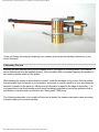
Schroder The Reference Tonearm
Dear customer
Congratulations! You have purchased a tonearm that, in order to allow the most accurate AND musical
reproduction of your records, features a bearing that differs from all other tonearms available. To take full
advantage of this inherently superior design even experienced "vinylists" should take the time to study
this manual.
file:///C|/Downloads/schroder-ref-manual.htm (1 of 10)7/18/2006 11:43:04 AM
Schroder Reference Schroeder Reference User Manual - Soundscape HiFi And Music
I hope you’ll enjoy mounting and adjusting your tonearm as much as the following rediscovery of your
record collection.
1) Mounting The Arm
Mounting the arm requires drilling two M4-tapped holes in your plinth or mounting board. The location
can be determined from the supplied drawing. Most turntables differ somewhat regarding the position of
the mounting boards relative to the platter.
While keeping the spindle to pivot distance constant, rotate the armbase until you have found a position
that allows both free movement of your armwand and results in a resting position of your arm where the
armwand is parallel to the plinth (or offering enough clearance in regard to the edge of the platter). It is
not hypercritical to get this distance spot on since overhang is adjusted by turning the armbase clock-or
anticlockwise (same principle as utilized in the "sliding base" SME-arms).
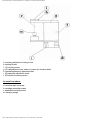
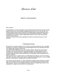
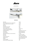
The following schematics (not to scale) will help you to identify the tonearm parts and screws necessary
to properly align your arm and cartridge:
file:///C|/Downloads/schroder-ref-manual.htm (2 of 10)7/18/2006 11:43:04 AM
Schroder Reference Schroeder Reference User Manual - Soundscape HiFi And Music
a: overhang adjustment locking screw
e: bearing thread
f: VTA locking screw
g: VTA adjustment screw, raises or lowers the tonearm block
h: Antiskating/damping adjustment disc
i: M3-damping adjustment screw
l: M4-tonearm mounting screw
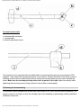
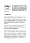
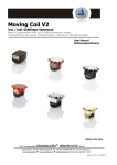
As seen from above:
d: counterweight set-screw
b: cartridge mounting-screws
c: headshell mounting-screw
m: damping trough
file:///C|/Downloads/schroder-ref-manual.htm (3 of 10)7/18/2006 11:43:04 AM
Schroder Reference Schroeder Reference User Manual - Soundscape HiFi And Music
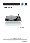
As seen from the side:
d: counterweight set-screw
j: tonearmwand
k: azimuth adjustment screw
The tonearm is to be screwed to the turntable plinth or mounting board using two non-magnetic (V2Asupplied-, V4A, brass) M4-cylinderhead-screws (l) from below. Choose the length of the screw so that a
minimum of 6mm of the screws will be sticking out from the tonearm base once you have inserted the
screw. Make sure the overhang-locking-screw hole (a) points to the right (seen from above) while
tightening the mounting screws (using excessive force yields no advantages).
2) Dressing the tonearmwiring
This tonearm comes standard with a cable that was chosen for it’s sonic and mechanical properties. The
signal is carried in a single run from the cartridge clips to the headamp or phonostage omitting additional
soldered connections..
file:///C|/Downloads/schroder-ref-manual.htm (4 of 10)7/18/2006 11:43:04 AM
Schroder Reference Schroeder Reference User Manual - Soundscape HiFi And Music
Depending on your turntable the cable can be fixed to the plinth/armboard by means of a clamp to be
screwed to the side of the plinth or utilizing a circular cable dressing base (provided upon request) which
requires an additional 16mm hole. To reduce the "spring"-effect of the wiring put the arm (wand), still
without the counterweight mounted, towards the inner groove. Whether you’re using a clamp, the wiring
base or just tape to fix the wiring to the plinth makes no difference as long as the non-shielded section
from it’s exit point in the armwand to the fixation point on the plinth forms an arc(180° – 270°) allowing for
the arm to move freely without the wiring touching the plinth. Please try to keep a distance of at least
10mm between the magnet assembly and the wiring. The restoring force of the supplied wiring is small
and it can easily be "bent" into shape, though sharp bends are to be avoided.
3) Electrical connections, grounding
The conductors/connectors are colour-coded according to the international standard:
Red = right channel, hot
Green = right channel, ground
White = left channel, hot
Blue = left channel, ground
RCA plugs: red = right channel ; black = left channel
The standard wiring is shielded from the arm to the RCA-plugs. The "ground" wire is to be connected to
the following amplification stage’s "ground". If you use a "star grounding" pattern, connect the ground
wire to your "central" ground.
4) Adjusting your tonearm/cartridge
4.1) Prepare Magnets
First remove the cardboard/foam strip sitting between the magnets. It was placed there to prevent
excessive movement during shipping. This bearing is, unlike many other bearing types, not susceptible to
shock induced damage. It is still advisable to keep the cardboard strip for later transports (any
appropriately folded piece of paper will do).
4.2) Mounting your cartridge
The cartridge can be mounted in the headshell using the supplied M2.5 non.magnetic stainless stell
screws (b). You might prefer to first seperate the mounting plate from the armwand by unscrewing the M3connection-screw (c) .
Usually it is sufficient to tighten the M2.5 screws well, but not excessively so. Overtightened screws can
result in internal tensions in the cartridge body, negatively affecting the sound or even damaging the
internal structure. Don’t forget: the next step after "REALLY tight" is "totally loose".
Connecting the mounting plate with the armwand requires tightening screw c, the same rules apply.
file:///C|/Downloads/schroder-ref-manual.htm (5 of 10)7/18/2006 11:43:04 AM
Schroder Reference Schroeder Reference User Manual - Soundscape HiFi And Music
4.3) Tracking force and overhang
Take the counterweight and slide it onto the back section of the armwand. Leave your "stylus cover" (if
your cartridge features such a device) on and set the tracking force to approx. 1.5 gr. Tighten the
counterweight set screw (d) just so that you can still slide the counterweight without applying much
pressure.
Using a proper template (i.e. Dennesen or the one that comes with the arm) the overhang is now adjusted
by rotating the entire armbase around it’s central post after loosening the overhang-locking-screw (a).
Using the aforementioned alignment gauges will automatically result in achieving a proper "outer" zeropoint (120.9mm) once you have managed to get the "inner" zero-point(66.04mm) right.
The overhang-locking-screw (a) should be tightened now.
Next, check the tangency of the cantilever as seen from above – with the stylus not quite touching the
alignment gauge – and, if neccessary, turn the headshell mounting plate after loosening screw (c) in the
right direction.
Finally, tighten screw (c) again.
4.4) VTA-adjustment
As a starting point you should raise or lower the tonearmblock until the armwand appears to be parallel to
the record surface with the needle in the groove.
Just unscrew the VTA-set screw (f) une full turn, insert a 3mm Allen key into the center hole and turn the
(hidden) VTA-adjustment screw (g) clockwise to lower the arm or counterclockwise to raise the arm (make
shure that the Allen key caught the screw).
Don’t forget to tighten the VTA-set screw (f) again.
This adjustment is NOT to be carried out during play!
You can use your Allen key and it’s position relative to the four screw heads holding the top plate of the
armbase as a gauge/reminder how far you’ve turned it. One full turn alters the VTA by 0.7mm.
4.5) Antiskating
To compensate for the skatingforce turn the antiskating-adjustment-disc (h) counterclockwise to increase
force (initially, several turns might be required!) and clockwise to reduce it. A good compromise will be
achieved once mistracking occurs in both channels simultaneously while playing the tracking ability test
tracks on the ORTOFON test record (0002 or 0003). In case you have no access to any such test record
just put the diamond on the space between the leadout grooves (or a "blank" record, i.e. Cardas sweeper
record) and adjust antiskating until the arm/cartridge combo wanders slowly towards the center of the
record.
From then on, use your ears...
file:///C|/Downloads/schroder-ref-manual.htm (6 of 10)7/18/2006 11:43:04 AM
Schroder Reference Schroeder Reference User Manual - Soundscape HiFi And Music
4.6) Adjusting the gap between the magnets
With a decent light source placed behind your record player it is easy to make out (and control) the gap
between the magnets which facilitates friction-free movement of the tonearm.
The distance between the magnets determines the effectiveness of damping both tonearm/cartridge
resonance and "parasitic" energy, generated by the cartridge or the turntable.
The smaller the gap the higher the damping and vice versa.
The gap between the magnets is altered by first inserting a 1.5mm Allen key into the set screw (i) , sitting
in the middle of disc (h). You then hold the Allen key steady while turning the disc clockwise to widen the
gap or counterclockwise to close it.
This sounds a lot more difficult than what it is..
The gap should be at least 0.3mm wide, enough to allow for a common business card to be slid in without
to much resistance.
If the magnets were to touch each other during play the resulting friction would cause the cartridge to skip.
The suspension thread used has an extremely high tensile strength, a very hard surface and will not
deteriorate over time.
It does stretch (break in) though over a period of two weeks max. (usually, it takes three days only). Once it
has set, only under extreme conditions (very high temperatures + high humidity) can the thread exhibit a
tendency to "give" a little more. So check the gap after a summer thunder storm (no more stretching after
three of those).
4.7) Silicon damping or not
The arm features the option to use silicon oil (i.e.SME2013) to dampen the tonearm resonance –
predominantly in the axis of the armwand – resulting in a reduction of the "wiggliness" commonly
associated with unipivot tonearms. This has almost no bearing(pun intended) on the tonearm/cartridge
resonance whicht is a function of the eff. mass of the arm, the compliance of the cartridge and it’s mass.
Simply dip a piece of non-magnetic wire (brass, copper...) into the silicon fluid, wait until a drop has formed
and wipe it off onto the thread (near it’s upper end). The drop will slowly travel down the thread until it
finally vanished in the small oil well where the thread enters the armwand. Repeat until you’re satisfied with
the sonic results (do not overfill). Common silicon fluid has no adverse effect on the thread or the bearing
in general, excess fluid can be wiped off using a cotton swab.
The effect resulting from that procedure depends upon the cartridge used and usually increases perceived
"blackness" between notes and solidity of images without sacrificing "attack" and "air". Some cartridges
(recent Lyras for example) sound better without any additional damping.
file:///C|/Downloads/schroder-ref-manual.htm (7 of 10)7/18/2006 11:43:04 AM
Schroder Reference Schroeder Reference User Manual - Soundscape HiFi And Music
5) The "Finetuning"
Everyone who has to mount cartridges frequently understands the importance of precisely adjusting an
arm/cartridge combination to release it’s full potential.
Overhang, azimuth, VTA, tracking force and, if featured, variable damping of the arm movement are all
important parameters.
The overhang adjustment was described already, nevertheless let me add that a single "perfect" overhang
setting does not exist. Should you own a lot of records that are cut close to the inner groove you might
consider using 63mm instead of 66mm as your inner "zero point" – many crescendo finales of symphonic
works could be tracked with reduced distortion this way.
On the other hand exist a lot of "pop"-records with no modulation, but leadout groove already where the
"inner" zero point is located. One doesn’t even benefit from this second distorsion minimum..
Correct overhang adjustment results in max. tracing-error-related tracking distortion of barely more than
0.6% for an arm with 239mm eff. length, 0.47% for a 305mm arm.
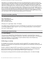
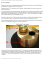
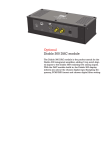
Fine-Tuning VTF and Azimuth
Please refer to the above photo for fine-tuning VTF. After getting the tracking force somewhere in the
neighborhood of the cartridge manufacturer's suggestion, you can screw the knurled wheel ("A" on the
photo) on the back out (away from the bearing to decrease the VTF and in (towards the bearing) to
increase VTF. To start out it might be best to screw it out a little, this gives you more leeway in both
directions.
file:///C|/Downloads/schroder-ref-manual.htm (8 of 10)7/18/2006 11:43:04 AM
Schroder Reference Schroeder Reference User Manual - Soundscape HiFi And Music
Next, the azimuth should be adjusted so that crosstalk is the same for both channels. Taken that both
channels of your cartridge are identical, a close approximationof the correct setting can be achieved by
playing a mono record back via an X-adaptor or through your preamp switched to mono.
Reverse the headshell clips on one channel only (switch red and green i.e.) and adjust for the weakest
signal coming from your speakers. But: If your cartridge has different output levels for each channel, this
method will result in a less than perfect setting!
To achieve consistently optimal results use a test record (i.e. Ortofon 0002) and follow the directions,
alternatively Wally Malewicz (contact : [email protected]) offers an appropriate set of measuring tools.
Once you’ve "hit it on the nail" a centrally recorded female voice should be precisely located in space
with no difference in the decay caracteristics between channels.
The proper way to adjust azimuth is by turning the counterweight set screw loose enough to allow turning
the counterweight clock-or anticlockwise until the headshell plate appears to be parallel with the record
surface.
Fine adjustment is achieved by inserting a narrow blade (<3mm) -screwdriver into the hole on the right side
of the counterweight (hold the armwand with two fingers while doing this), then turning the internal grub
screw (A in the photo above) inward or outward, altering the counterweight’s center of gravity ever so
slightly. Please refer to the photo above, "B" is where the grub screw is located. This adjustment covers a
range of no more than +/- 1.5°. This should suffice to compensate for minor misalignments of the stylus/
cantilever assembly.
Starting with the armwand parallel to the record surface, VTA adjustment can be carried out in small steps
(i.e. 0.2mm, ~ a quarter turn of the Allen key) until the best separation between individual instrument in
space, the least amount of "grain" audible and the best integration of fundamentals and upper harmonics is
achieved.
There is no "perfect" position, varying record thicknesses and a different cutting angle used for most
records made before 1965 neccesitate a new setting for every other record. Stylus shapes are also more
or less susceptible to changes in the VTA – the "sharper" the stylus, the more sensitive to changes..) The
more time you spend on adjusting the VTA the less you’ll get to actually enjoy your records.
The tracking force determines the tracking ability and also the position of the coils in the magnetic
generator. Follow the manufacturer’s recommendation and try increasing or lowering the tracking force by
increments of 0.1gr. Low frequency tracking ability shouldn’t be lower than 70my. Soundwise more
relevant is the high frequency tracking ability. The appropriate tracks on the Shure TT115 test record are
helpful to get closer to the optimal tracking force.
file:///C|/Downloads/schroder-ref-manual.htm (9 of 10)7/18/2006 11:43:04 AM
Schroder Reference Schroeder Reference User Manual - Soundscape HiFi And Music
The damping is , as already mentioned, a function of the distance between the magnets, or, more
precisely, the flux density in the gap between the magnets.
It is to be adjusted so that the lower registers will be reproduced with control and heft without loosing the
resolution of high frequency fine detail and "air".
Overdamping this arm is close to impossible (often the case with silicone fluid damped arms) but rarely
does the smallest gap result in the most satisfying sound.
The amount of tightening of any of the arm’s screws has an influence on the energy transmission and
therefore dissipation and should be experimented with.
Generally speaking, only screws a, l and f should be tightened well. Screws b, c, and d require some
experimentation.
Oh,.. and leave the screw underneath the lower magnet alone. Once you’ve loosened it , the magnets
require realignment for which the arm needs to be send back to me.
Should you have any questions regarding mounting/adjusting or technical details of this tonearm,
feel free to contact me via phone or email.
Equally welcome is any sort of criticism or suggestions for improvements.
Yours truly
Frank Schröder
email: [email protected]
phone: ++49 30 / 611 51 81
Schroder Reference Tonearm User Manual
file:///C|/Downloads/schroder-ref-manual.htm (10 of 10)7/18/2006 11:43:04 AM