1
DeviceNet Option Board for 9000X Drive
User Manual
New Information
March 2004
MN04003005E
For more information visit: www.eatonelectrical.com
DeviceNet Option Board User Manual
March 2004
Important Notice – Please Read
The product discussed in this literature is subject to terms and conditions outlined in Eaton
Electrical Inc. selling policies. The sole source governing the rights and remedies of any
purchaser of this equipment is the relevant Eaton Electrical Inc. selling policy.
NO WARRANTIES, EXPRESS OR IMPLIED, INCLUDING WARRANTIES OF FITNESS FOR A
PARTICULAR PURPOSE OR MERCHANTABILITY, OR WARRANTIES ARISING FROM COURSE
OF DEALING OR USAGE OF TRADE, ARE MADE REGARDING THE INFORMATION,
RECOMMENDATIONS AND DESCRIPTIONS CONTAINED HEREIN. In no event will Eaton
Electrical Inc. be responsible to the purchaser or user in contract, in tort (including
negligence), strict liability or otherwise for any special, indirect, incidental or consequential
damage or loss whatsoever, including but not limited to damage or loss of use of equipment,
plant or power system, cost of capital, loss of power, additional expenses in the use of
existing power facilities, or claims against the purchaser or user by its customers resulting
from the use of the information, recommendations and descriptions contained herein.
The information contained in this manual is subject to change without notice.
Cover Photo: Cutler-Hammer® 9000X Drives.
MN04003005E
For more information visit: www.eatonelectrical.com
i
DeviceNet Option Board User Manual
March 2004
Table of Contents
ii
LIST OF FIGURES . . . . . . . . . . . . . . . . . . . . . . . . . . . . . . . . . . . . . . . . . . . . . . . . . . . . . . . . .
LIST OF TABLES . . . . . . . . . . . . . . . . . . . . . . . . . . . . . . . . . . . . . . . . . . . . . . . . . . . . . . . . . .
SAFETY . . . . . . . . . . . . . . . . . . . . . . . . . . . . . . . . . . . . . . . . . . . . . . . . . . . . . . . . . . . . . . . . .
Definitions and Symbols . . . . . . . . . . . . . . . . . . . . . . . . . . . . . . . . . . . . . . . . . . . . . . .
Hazardous High Voltage . . . . . . . . . . . . . . . . . . . . . . . . . . . . . . . . . . . . . . . . . . . . . . .
Warnings, Cautions and Notices. . . . . . . . . . . . . . . . . . . . . . . . . . . . . . . . . . . . . . . . .
iii
iii
v
v
v
vi
CHAPTER 1 — GENERAL . . . . . . . . . . . . . . . . . . . . . . . . . . . . . . . . . . . . . . . . . . . . . . . . . . .
CHAPTER 2 — DEVICENET OPTION BOARD TECHNICAL DATA . . . . . . . . . . . . . . . . . . .
General . . . . . . . . . . . . . . . . . . . . . . . . . . . . . . . . . . . . . . . . . . . . . . . . . . . . . . . . . . . . .
DeviceNet Features and Functionality . . . . . . . . . . . . . . . . . . . . . . . . . . . . . . . . . . . .
1-1
2-1
2-1
2-2
CHAPTER 3 — DEVICENET . . . . . . . . . . . . . . . . . . . . . . . . . . . . . . . . . . . . . . . . . . . . . . . . .
Introduction . . . . . . . . . . . . . . . . . . . . . . . . . . . . . . . . . . . . . . . . . . . . . . . . . . . . . . . . .
DeviceNet Physical Layer and Media . . . . . . . . . . . . . . . . . . . . . . . . . . . . . . . . . . . . .
3-1
3-1
3-1
CHAPTER 4 — DEVICENET OPTION BOARD LAYOUT AND CONNECTIONS . . . . . . . .
DeviceNet Option Board . . . . . . . . . . . . . . . . . . . . . . . . . . . . . . . . . . . . . . . . . . . . . . .
LED Indications. . . . . . . . . . . . . . . . . . . . . . . . . . . . . . . . . . . . . . . . . . . . . . . . . . . . . . .
Connection of DeviceNet Drop-Line Cable. . . . . . . . . . . . . . . . . . . . . . . . . . . . . . . . .
4-1
4-1
4-2
4-3
CHAPTER 5 — INSTALLATION OF DEVICENET OPTION BOARD . . . . . . . . . . . . . . . . . .
Board Information Sticker . . . . . . . . . . . . . . . . . . . . . . . . . . . . . . . . . . . . . . . . . . . . . .
5-1
5-3
CHAPTER 6 — COMMISSIONING . . . . . . . . . . . . . . . . . . . . . . . . . . . . . . . . . . . . . . . . . . . .
DeviceNet Configuration Tool . . . . . . . . . . . . . . . . . . . . . . . . . . . . . . . . . . . . . . . . . . .
Setting DeviceNet Parameters with the Control Keypad . . . . . . . . . . . . . . . . . . . . .
6-1
6-1
6-2
CHAPTER 7 — DEVICENET INTERFACE . . . . . . . . . . . . . . . . . . . . . . . . . . . . . . . . . . . . . . .
I/O Messaging. . . . . . . . . . . . . . . . . . . . . . . . . . . . . . . . . . . . . . . . . . . . . . . . . . . . . . . .
Input and Output Assemblies . . . . . . . . . . . . . . . . . . . . . . . . . . . . . . . . . . . . . . . . . . .
Explicit Messaging . . . . . . . . . . . . . . . . . . . . . . . . . . . . . . . . . . . . . . . . . . . . . . . . . . . .
7-1
7-1
7-2
7-6
CHAPTER 8 — FAULT TRACKING . . . . . . . . . . . . . . . . . . . . . . . . . . . . . . . . . . . . . . . . . . . .
APPENDIX A — DEVICENET INTERFACE ERRORS . . . . . . . . . . . . . . . . . . . . . . . . . . . . . .
APPENDIX B — OPTC7 COMMUNICATION INTERFACE OBJECT PROFILES . . . . . . . . .
Identity Object . . . . . . . . . . . . . . . . . . . . . . . . . . . . . . . . . . . . . . . . . . . . . . . . . . . . . . .
Message Router Object . . . . . . . . . . . . . . . . . . . . . . . . . . . . . . . . . . . . . . . . . . . . . . . .
DeviceNet Object . . . . . . . . . . . . . . . . . . . . . . . . . . . . . . . . . . . . . . . . . . . . . . . . . . . . .
Assembly Object . . . . . . . . . . . . . . . . . . . . . . . . . . . . . . . . . . . . . . . . . . . . . . . . . . . . .
DeviceNet Connection Object . . . . . . . . . . . . . . . . . . . . . . . . . . . . . . . . . . . . . . . . . . .
Motor Data Object . . . . . . . . . . . . . . . . . . . . . . . . . . . . . . . . . . . . . . . . . . . . . . . . . . . .
Control Supervisor Object . . . . . . . . . . . . . . . . . . . . . . . . . . . . . . . . . . . . . . . . . . . . . .
AC/DC Drive Object . . . . . . . . . . . . . . . . . . . . . . . . . . . . . . . . . . . . . . . . . . . . . . . . . . .
Parameter Object . . . . . . . . . . . . . . . . . . . . . . . . . . . . . . . . . . . . . . . . . . . . . . . . . . . . .
Monitoring Data Object . . . . . . . . . . . . . . . . . . . . . . . . . . . . . . . . . . . . . . . . . . . . . . . .
8-1
A-1
B-1
B-1
B-3
B-4
B-6
B-9
B-12
B-14
B-17
B-19
B-20
For more information visit: www.eatonelectrical.com
MN04003005E
DeviceNet Option Board User Manual
March 2004
List of Figures
Figure 3-1: Trunk Lines or Drop Lines . . . . . . . . . . . . . . . . . . . . . . . . . . . . . . . . . . . . . . . . .
Figure 4-1: DeviceNet Option Board OPTC7 . . . . . . . . . . . . . . . . . . . . . . . . . . . . . . . . . . . .
Figure 4-2: LED Indications on the DeviceNet Board . . . . . . . . . . . . . . . . . . . . . . . . . . . . .
Figure 5-1: Identification Sticker . . . . . . . . . . . . . . . . . . . . . . . . . . . . . . . . . . . . . . . . . . . . .
Figure 6-1: Changing the DeviceNet Board Parameter Values . . . . . . . . . . . . . . . . . . . . .
Figure 6-2: DeviceNet Status . . . . . . . . . . . . . . . . . . . . . . . . . . . . . . . . . . . . . . . . . . . . . . . .
Figure 7-1: DeviceNet I/O Messaging . . . . . . . . . . . . . . . . . . . . . . . . . . . . . . . . . . . . . . . . .
Figure 7-2: Control Supervisor State Transition Diagram . . . . . . . . . . . . . . . . . . . . . . . . .
3-2
4-1
4-2
5-3
6-3
6-4
7-1
7-4
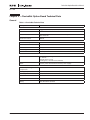
List of Tables
Table 2-1: DeviceNet Technical Data. . . . . . . . . . . . . . . . . . . . . . . . . . . . . . . . . . . . . . . . . . .
Table 2-2: DeviceNet Features and Functionality . . . . . . . . . . . . . . . . . . . . . . . . . . . . . . . .
Table 4-1: OPTC7 Bus Connector Signals . . . . . . . . . . . . . . . . . . . . . . . . . . . . . . . . . . . . . .
Table 4-2: Network Status LED (N) . . . . . . . . . . . . . . . . . . . . . . . . . . . . . . . . . . . . . . . . . . . .
Table 4-3: Module Status LED (M) . . . . . . . . . . . . . . . . . . . . . . . . . . . . . . . . . . . . . . . . . . . .
Table 4-4: Connection and Power-Up . . . . . . . . . . . . . . . . . . . . . . . . . . . . . . . . . . . . . . . . . .
Table 5-1: Installation of DeviceNet Option Board . . . . . . . . . . . . . . . . . . . . . . . . . . . . . . .
Table 6-1: Monitoring Data Class — Instance Attributes . . . . . . . . . . . . . . . . . . . . . . . . . .
Table 6-2: DeviceNet Parameters . . . . . . . . . . . . . . . . . . . . . . . . . . . . . . . . . . . . . . . . . . . . .
Table 6-3: DeviceNet Status Indications . . . . . . . . . . . . . . . . . . . . . . . . . . . . . . . . . . . . . . . .
Table 7-1: Output 20 . . . . . . . . . . . . . . . . . . . . . . . . . . . . . . . . . . . . . . . . . . . . . . . . . . . . . . . .
Table 7-2: Output 21 (Default) . . . . . . . . . . . . . . . . . . . . . . . . . . . . . . . . . . . . . . . . . . . . . . . .
Table 7-3: Output 23 . . . . . . . . . . . . . . . . . . . . . . . . . . . . . . . . . . . . . . . . . . . . . . . . . . . . . . . .
Table 7-4: Output 25 . . . . . . . . . . . . . . . . . . . . . . . . . . . . . . . . . . . . . . . . . . . . . . . . . . . . . . . .
Table 7-5: Input 70 . . . . . . . . . . . . . . . . . . . . . . . . . . . . . . . . . . . . . . . . . . . . . . . . . . . . . . . . .
Table 7-6: Input 71 (Default) . . . . . . . . . . . . . . . . . . . . . . . . . . . . . . . . . . . . . . . . . . . . . . . . .
Table 7-7: Input 73 . . . . . . . . . . . . . . . . . . . . . . . . . . . . . . . . . . . . . . . . . . . . . . . . . . . . . . . . .
Table 7-8: Input 75 . . . . . . . . . . . . . . . . . . . . . . . . . . . . . . . . . . . . . . . . . . . . . . . . . . . . . . . . .
Table 7-9: Explanation of the Control Supervisor State Transition Diagram . . . . . . . . . .
Table 7-10: Object Classes . . . . . . . . . . . . . . . . . . . . . . . . . . . . . . . . . . . . . . . . . . . . . . . . . . .
Table 7-11: Supported Services . . . . . . . . . . . . . . . . . . . . . . . . . . . . . . . . . . . . . . . . . . . . . .
Table 7-12: Elementary Data Types . . . . . . . . . . . . . . . . . . . . . . . . . . . . . . . . . . . . . . . . . . .
Table 7-13: Constructed Data Types . . . . . . . . . . . . . . . . . . . . . . . . . . . . . . . . . . . . . . . . . . .
Table 7-14: Inverter Configuration . . . . . . . . . . . . . . . . . . . . . . . . . . . . . . . . . . . . . . . . . . . .
Table 8-1: DeviceNet Option Board Faults . . . . . . . . . . . . . . . . . . . . . . . . . . . . . . . . . . . . . .
Table 8-2: Drive Responses to Faults . . . . . . . . . . . . . . . . . . . . . . . . . . . . . . . . . . . . . . . . . .
Table A-1: Event List. . . . . . . . . . . . . . . . . . . . . . . . . . . . . . . . . . . . . . . . . . . . . . . . . . . . . . . .
Table B-1: Identity Class (1) — Class Attributes (0) . . . . . . . . . . . . . . . . . . . . . . . . . . . . . . .
Table B-2: Identity Class (1) — Instance Attributes (1) . . . . . . . . . . . . . . . . . . . . . . . . . . . .
Table B-3: Message Router Class (2) — Class Attributes (0). . . . . . . . . . . . . . . . . . . . . . . .
Table B-4: Message Router Class (2) — Instance Attributes (1) . . . . . . . . . . . . . . . . . . . . .
Table B-5: DeviceNet Class (3) — Class Attributes (0). . . . . . . . . . . . . . . . . . . . . . . . . . . . .
Table B-6: DeviceNet Class (3) — Instance Attributes (1) . . . . . . . . . . . . . . . . . . . . . . . . . .
Table B-7: Assembly Class (4) — Class Attributes (0) . . . . . . . . . . . . . . . . . . . . . . . . . . . . .
Table B-8: Assembly Class (4) — Basic Control (20) . . . . . . . . . . . . . . . . . . . . . . . . . . . . . .
Table B-9: Assembly Class (4) — Speed Control (21) . . . . . . . . . . . . . . . . . . . . . . . . . . . . .
MN04003005E
For more information visit: www.eatonelectrical.com
2-1
2-2
4-1
4-2
4-2
4-3
5-1
6-1
6-3
6-4
7-2
7-2
7-2
7-2
7-2
7-3
7-3
7-3
7-5
7-6
7-7
7-8
7-8
7-9
8-1
8-1
A-1
B-1
B-2
B-3
B-4
B-4
B-5
B-6
B-7
B-7
iii
DeviceNet Option Board User Manual
March 2004
List of Tables, continued
Table B-10: Assembly Class (4) — Torque Control (23) . . . . . . . . . . . . . . . . . . . . . . . . . . .
Table B-11: Assembly Class (4) — Extended Process Control (25) . . . . . . . . . . . . . . . . . .
Table B-12: Assembly Class (4) — Basic Status (70) . . . . . . . . . . . . . . . . . . . . . . . . . . . . .
Table B-13: Assembly Class (4) — Speed Status (71) . . . . . . . . . . . . . . . . . . . . . . . . . . . .
Table B-14: Assembly Class (4) — Torque Status (73) . . . . . . . . . . . . . . . . . . . . . . . . . . . .
Table B-15: Assembly Class (4) — Extended Process Control (75) . . . . . . . . . . . . . . . . . .
Table B-16: DeviceNet Connection Class (5) — Class Attributes (0) . . . . . . . . . . . . . . . . .
Table B-17: DeviceNet Connection Class (5) — Explicit Connection Instance (1) . . . . . .
Table B-18: DeviceNet Connection Class (5) — I/O Connection Instance (1) . . . . . . . . . .
Table B-19: Motor Data Object Class (40) — Class Attributes (0) . . . . . . . . . . . . . . . . . . .
Table B-20: Motor Data Object Class (40) — Instance Attributes (1). . . . . . . . . . . . . . . . .
Table B-21: Control Supervisor Object Class (41) — Class Attributes (0). . . . . . . . . . . . .
Table B-22: Control Supervisor Object Class (41) — Instance Attributes (1) . . . . . . . . . .
Table B-23: AC/DC Drive Object Class (42) — Class Attributes (0) . . . . . . . . . . . . . . . . . .
Table B-24: AC/DC Drive Object Class (42) — Instance Attributes (1). . . . . . . . . . . . . . . .
Table B-25: Parameter Class (160) — Class Attributes (0) . . . . . . . . . . . . . . . . . . . . . . . . .
Table B-26: Parameter Class (160) — Class Attributes (1) . . . . . . . . . . . . . . . . . . . . . . . . .
Table B-27: Monitoring Data Class (170) — Class Attributes (0) . . . . . . . . . . . . . . . . . . . .
Table B-28: Monitoring Data Class (170) — Instance Attributes (1) . . . . . . . . . . . . . . . . .
iv
For more information visit: www.eatonelectrical.com
B-7
B-7
B-7
B-8
B-8
B-8
B-9
B-10
B-11
B-12
B-13
B-14
B-15
B-17
B-18
B-19
B-20
B-20
B-21
MN04003005E
DeviceNet Option Board User Manual
March 2004
Safety
Definitions and Symbols
WARNING
This symbol indicates high voltage. It calls your attention to items
or operations that could be dangerous to you and other persons
operating this equipment. Read the message and follow the
instructions carefully.
This symbol is the “Safety Alert Symbol.” It occurs with either of
two signal words: CAUTION or WARNING, as described below.
WARNING
Indicates a potentially hazardous situation which, if not avoided,
can result in serious injury or death.
CAUTION
Indicates a potentially hazardous situation which, if not avoided,
can result in minor to moderate injury, or serious damage to the
product. The situation described in the CAUTION may, if not
avoided, lead to serious results. Important safety measures are
described in CAUTION (as well as WARNING).
Hazardous High Voltage
WARNING
Motor control equipment and electronic controllers are connected
to hazardous line voltages. When servicing drives and electronic
controllers, there may be exposed components with housings or
protrusions at or above line potential. Extreme care should be taken
to protect against shock.
Stand on an insulating pad and make it a habit to use only one
hand when checking components. Always work with another
person in case an emergency occurs. Disconnect power before
checking controllers or performing maintenance. Be sure
equipment is properly grounded. Wear safety glasses whenever
working on electronic controllers or rotating machinery.
MN04003005E
For more information visit: www.eatonelectrical.com
v
DeviceNet Option Board User Manual
March 2004
Warnings, Cautions and Notices
WARNING
Internal components and circuit boards are at high potential when
the drive is connected to the power source. This voltage is
extremely dangerous and may cause death or severe injury if you
come into contact with it.
CAUTION
Make sure that the drive IS SWITCHED OFF before an option or
fieldbus board is changed or added.
!
IMPORTANT
Before taking any commissioning actions, carefully read the safety
instructions in the 9000X User’s Manual.
vi
For more information visit: www.eatonelectrical.com
MN04003005E
DeviceNet Option Board User Manual
March 2004
Chapter 1 — General
Instead of sending and receiving information to and from adjustable frequency drives
through I/O, you can connect them to a fieldbus.
Cutler-Hammer® 9000X drives from Eaton Electrical® can be connected to the DeviceNet
using a fieldbus board. The drive can then be controlled, monitored and programmed from
the Host system.
If you purchase your DeviceNet Option Board separately, please note that the it shall be
installed in Slot E on the control board of the drive.
WARNING
Internal components and circuit boards are at high potential when
the drive is connected to the power source. This voltage is
extremely dangerous and may cause death or severe injury if you
come into contact with it.
MN04003005E
For more information visit: www.eatonelectrical.com
1-1
DeviceNet Option Board User Manual
March 2004
1-2
For more information visit: www.eatonelectrical.com
MN04003005E
DeviceNet Option Board User Manual
March 2004
Chapter 2 — DeviceNet Option Board Technical Data
General
Table 2-1: DeviceNet Technical Data
Description
Specification
DeviceNet Connections
Interface
Pluggable connector (5.08 mm)
Data transfer method
CAN
Transfer cable
2 wire twisted shielded cable with 2 wire bus power
cable and drain
Electrical isolation
500V DC
Communications
ODVA 2.0 Compliant
Baud rate
125, 250 and 500 kBaud
Product code
0x02 (2)
Product type
0x02 (AC Drive)
Vendor ID
0 x 1BB ()
Electrical
DeviceNet
Network supply voltage:
11 – 25V DC
Network input current:
28 mA typical, 125 mA inrush (24V DC)
Other
All other power derived from inverter power supply
Environment
MN04003005E
Ambient operating
temperature
-10°C – 55°C
Storing temperature
-40°C – 60°C
Humidity
<95%, no condensation allowed
Altitude
Max. 1000m
Vibration
0.5G at 9 – 200 Hz
Safety
Fulfils EN 50178 standard
For more information visit: www.eatonelectrical.com
2-1
DeviceNet Option Board User Manual
March 2004
DeviceNet Features and Functionality
Table 2-2: DeviceNet Features and Functionality
Description
Specification
Network size
Up to 64 nodes
Network length
2-2
Selectable end-to-end network distance varies with speed
Baud Rate
Distance
125 Kbps
500m
250 Kbps
250m
500 Kbps
100m
Data packets
0 – 8 bytes
Bus topology
Linear (trunk-line/drop-line); power and signal on the same network cable
Bus addressing
Peer-to-peer with Multi-Cast (one-to-many); Multi-Master and Master/Slave
special case; polled or change-of-state (exception-based)
System features
Removal and replacement of devices from the network under power
For more information visit: www.eatonelectrical.com
MN04003005E
DeviceNet Option Board User Manual
March 2004
Chapter 3 — DeviceNet
Introduction
DeviceNet is an open network based on CAN that is designed to connect low cost industrial
control devices (such as limit switches, photoelectric sensors, motor starters, process
sensors, adjustable frequency drives, panel displays and operator interfaces) to a network
and eliminate expensive hardwiring.
The direct connectivity provides improved communication between devices as well as
important device-level diagnostics not easily accessible or available through hardwired
I/O interfaces.
The DeviceNet Model is application independent; it provides the communication services
needed by various types of applications.
Many of today’s lower level industrial control devices must retain their low cost/low resource
characteristics even when directly connected to a network. DeviceNet takes this into
consideration by defining a specific instance of the Model for communications typically
seen in a Master/Slave application. This is referred to as the Predefined Master/Slave
Connection Set.
DeviceNet allows the interchangeability of simple devices while making interconnectivity for
more complex devices possible. In addition to reading the state of discrete devices,
DeviceNet provides the capability to report temperatures, to read the load current in a motor
starter, to change the deceleration rate of drives, or to count the number of packages that
have passed on a conveyor in the previous hour.
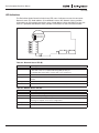
DeviceNet Physical Layer and Media
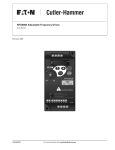
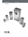
The basic trunk-line/drop-line topology provides separate twisted pair busses for both signal
and power distribution. Thick or thin cable can be used for either trunk lines or drop lines.
End-to-end network distance varies with data rate and cable size.
Devices can be powered directly from the bus and communicate with each other using the
same cable. Nodes can be removed or inserted from the network without powering down the
network.
Power taps can be added at any point in the network which makes redundant power supplies
possible. The trunk-line current rating is 8 amps. An opto-isolated design option allows
externally powered devices (e.g. AC drives, starters and solenoid valves) to share the same
bus cable. Other CAN-based networks allow only a single power supply (if at all) for the
entire network.
MN04003005E
For more information visit: www.eatonelectrical.com
3-1
DeviceNet Option Board User Manual
March 2004
Terminator
Tap
Terminator
Trunk Line
Node
Node
Drop
Line
Node
Node
Node
Node
Node
Node
Node
Node
Node
Zero Drop
Node
Node
Short Drops
Figure 3-1: Trunk Lines or Drop Lines
Thick or Thin Cable can be used for either trunk lines or drop lines.
3-2
For more information visit: www.eatonelectrical.com
MN04003005E
DeviceNet Option Board User Manual
March 2004
Chapter 4 — DeviceNet Option Board Layout and Connections
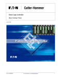
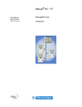
The Cutler-Hammer DeviceNet Option Board from Eaton Electrical is connected to the
fieldbus through a 5-pin pluggable bus connector (board OPTC7).
The communication with the control board of the drive takes place through the standard
Interface Board Connector.
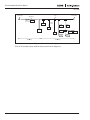
DeviceNet Option Board
N
A
M
1
2
3
4
5
X1
Bus
Grounding
Connector
Plate
Jumper
Interface
Board Connector
Figure 4-1: DeviceNet Option Board OPTC7
Table 4-1: OPTC7 Bus Connector Signals
MN04003005E
Signal
Connector
Description
V-
1
Communication power supply, Ground
CAN_L
2
Communication signal, Low
Drain
3
Cable shield (bare)
CAN_H
4
Communication signal, High
V+
5
Communication power supply, +24V
For more information visit: www.eatonelectrical.com
4-1
DeviceNet Option Board User Manual
March 2004
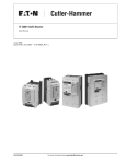
LED Indications
The DeviceNet Option Board includes three LED status indicators next to the connector:
Network status (N), Node address (A) and Module status (M). Network status provides
information on the network connection status, Node address blinks the MAC ID of the unit
while it is powered and Module status provides information on the DeviceNet module.
N Green/Red
A Green/Red
M Green/Red
1
2
3
4
5
X1
Figure 4-2: LED Indications on the DeviceNet Board
Table 4-2: Network Status LED (N)
LED is:
Meaning:
OFF
The OPTC7 is not on-line —
• The device has not completed the Dup_MAC_ID test yet
• If the Module status LED is off, the device is not powered
Green
The OPTC7 is on-line and allocated to a Master
Blinking Green
The OPTC7 has passed the Dup_MAC_ID test, is on-line, but is not allocated to a
master
Blinking Red
One or more I/O connections are in the Timed-Out state
Red
The OPTC7 cannot communicate on the network (Duplicate MAC ID or Bus-off)
Table 4-3: Module Status LED (M)
4-2
LED is:
Meaning:
OFF
There is no power applied to the OPTC7
Green
The OPTC7 is operating normally
Blinking Green
The OPTC7 board is in Standby state or the device needs commissioning due to a
missing, incomplete or incorrect configuration
Blinking Red
The option board has detected a Recoverable Fault
Red
The option board has detected an Unrecoverable Fault
For more information visit: www.eatonelectrical.com
MN04003005E
DeviceNet Option Board User Manual
March 2004
Node Address LED (A)
This LED blinks the MAC ID of the unit while it is powered. The tens are displayed with red
blinks and the ones with green blinks. The unit plays the tens, then the ones and finally
delays about 2 seconds before repeating the sequence.
LED Test
An LED test is performed at power-up. The following sequence is performed:
1. All LEDs OFF
2. All LEDs Green (0.25 s)
3. All LEDs Red (0.25 s)
4. All LEDs OFF
5. Start of Normal Operation
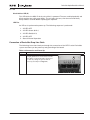
Connection of DeviceNet Drop-Line Cable
The following instructions lead you through the connection of the OPTC7 to the DeviceNet
system and show you the power-up and grounding of the board.
Table 4-4: Connection and Power-Up
MN04003005E
Step
Procedure
A
Lead the DeviceNet drop-line cable through
the right gridded hole on the bottom of the
drive. Make a sufficiently wide opening for
the cable by cutting the grid as wide as
necessary (see Step E on Page 5-2)
For more information visit: www.eatonelectrical.com
4-3
DeviceNet Option Board User Manual
March 2004
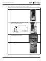
Table 4-4: Connection and Power-Up, continued
Step
Procedure
B
Connect the 4 colored wires into the bus
connector in the following order from the left:
black, blue, NONE, white, red.
1
2
3
4
BK BL
C
W
5
R
It is recommended that the bare wire is not
connected to any of the terminals. If it
however has to be connected, use the
terminal 3 as shown in the picture:
Note: If the bare wire is connected, the
jumper X1 must be set to OFF-position.
1
2
3
4
5
X1
BK BL BA W R
4-4
For more information visit: www.eatonelectrical.com
MN04003005E
DeviceNet Option Board User Manual
March 2004
Chapter 5 — Installation of DeviceNet Option Board
Note: These instructions apply only to field installations. Otherwise, the board has already
been installed for you at the factory.
CAUTION
Make sure that the drive IS SWITCHED OFF before an option or
fieldbus board is changed or added.
!
IMPORTANT
Before taking any commissioning actions, carefully read the safety
instructions in the 9000X User’s Manual.
Table 5-1: Installation of DeviceNet Option Board
MN04003005E
Step
Procedure
A
9000X Adjustable Frequency Drive.
B
Remove the cable cover.
For more information visit: www.eatonelectrical.com
5-1
DeviceNet Option Board User Manual
March 2004
Table 5-1: Installation of DeviceNet Option Board, continued
Step
Procedure
C
Open the cover of the control unit.
D
Install DeviceNet Option Board in Slot E on the control
board of the drive. Make sure that the grounding plate
(see below) fits tightly in the clamp.
N
A
M
1
2
3
4
5
Grounding
Plate
5-2
X1
E
Make a sufficiently wide opening for your
cable by cutting the grid as wide as
necessary.
F
Close the cover of the control unit and the
cable cover.
For more information visit: www.eatonelectrical.com
MN04003005E
DeviceNet Option Board User Manual
March 2004
Board Information Sticker
The DeviceNet Option Board package delivered by the factory includes a sticker (shown
below). Please mark the board type (1), the slot into which the board is mounted (2) and the
mounting date (3) on the sticker. Finally, attach the sticker on your drive.
3
1
Drive modified:
Option board:
OPT.................
in slot:
A B C D E
IP54 upgrade/ Collar
EMC level modified: H Y T / T Y H
Date:....................
Date:....................
Date:....................
2
Figure 5-1: Identification Sticker
MN04003005E
For more information visit: www.eatonelectrical.com
5-3
DeviceNet Option Board User Manual
March 2004
5-4
For more information visit: www.eatonelectrical.com
MN04003005E
DeviceNet Option Board User Manual
March 2004
Chapter 6 — Commissioning
Read first about Menu Navigation in the 9000X User’s Manual.
Note: You must select Fieldbus as the active control place, if you wish to control the drive
through fieldbus. See the 9000X User’s Manual.
The recommended method for setting the DeviceNet parameters is with a DeviceNet
Configuration Tool (see DeviceNet Configuration Tool below). However, the parameters can
also be set with the control keypad (see Setting DeviceNet Parameters with the Control
Keypad on Page 6-2), but then it must be ensured that the parameter settings correspond to
the settings in the Master system.
DeviceNet Configuration Tool
Before using the OPTC7 option board, you must configure the device baud rate and node
address to the desired values. This can be done by using a DeviceNet Configuration tool (e.g.
Netview or RSNetworx for DeviceNet). The default baud rate is 125 Kbaud and node address
63. All devices must have the same baud rate.
Since all new devices are factory set to node address 63, it is recommended that the address
is changed. You must also check or set the following attributes before use:
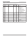
Monitoring Data Class (0xAA) — Instance Attributes
Table 6-1: Monitoring Data Class — Instance Attributes
Default —
Minimum,
Maximum
Data
Type
#
Attribute Name
Services
120
0x78
Polled Input
Assembly Type
Get_Attribute_Single,
Set_Attribute_Single
71
70
73
75
C7
Input assembly used by the polled
connection
121
0x79
Polled Output
Assembly Type
Get_Attribute_Single,
Set_Attribute_Single
21
20
23
25
C7
Output assembly used by the polled
connection
110
0x6E
SafeState Type
Get_Attribute_Single,
Set_Attribute_Single
0
0
2
C6
Selects Safe State response to errors
which specify safe state operation.
Currently only a loss of connection
other than by de-allocation is a safe
state error.
Warning: Review the application for
safe operation before specifying a
value for this attribute.
0 = DriveFault (fault and stop)
1 = No Action (hold last speed)
2 = Preset Speed/Direction
MN04003005E
For more information visit: www.eatonelectrical.com
Description
6-1
DeviceNet Option Board User Manual
March 2004
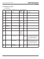
Table 6-1: Monitoring Data Class — Instance Attributes, continued
Default —
Minimum,
Maximum
Data
Type
#
Attribute Name
Services
Description
111
0x6F
PresetDir
Get_Attribute_Single,
Set_Attribute_Single
0
0
1
C1
Sets safe state direction of rotation if
the Safe State Behavior attribute
specifies “Preset Speed/Direction”
Warning: Review the application for
safe operation before specifying a
value for this attribute.
Inverter will require external stop.
0 = Forward
1 = Reverse
112
0x70
PresetRPM
Get_Attribute_Single,
Set_Attribute_Single
0
0
30000
C7
Sets safe state speed reference (RPM)
if the Safe State Behavior attribute
specifies “Preset Speed/Direction”
Warning: Review the application for
safe operation before specifying a
value for this attribute.
Inverter will require external stop.
113
0x71
PresetTq
Get_Attribute_Single,
Set_Attribute_Single
0
0
10000
C7
Sets safe state torque reference
(0.00%) if the Safe State Behavior
attribute specifies “Preset Speed/
Direction”
Warning: Review the application for
safe operation before specifying a
value for this attribute.
Inverter will require external stop.
Setting DeviceNet Parameters with the Control Keypad
If the control keypad is used in setting the parameters of the DeviceNet board, certain values
to appropriate parameters must be given in menu M7 (for locating the expander board menu
see 9000X User’s Manual).
Note: If you use the keypad for setting the parameters, make sure that the settings
correspond to the settings in the Master system.
Expander Board Menu (M7)
The Expander board menu makes it possible for the user 1) to see what expander boards are
connected to the control board and 2) to reach and edit the parameters associated with the
expander board.
Enter the following menu level (G#) with the menu button right. At this level, you can browse
through slots A to E with the browser buttons to see what expander boards are connected.
On the lowermost line of the display, you also see the number of parameter groups
associated with the board.
If you still press the menu button right once, you will reach the parameter group level where
there are two groups: Editable parameters and Monitored values. A further press on the
menu button right takes you to either of these groups.
6-2
For more information visit: www.eatonelectrical.com
MN04003005E
DeviceNet Option Board User Manual
March 2004
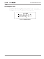
DeviceNet Parameters
To set the DeviceNet board parameters, enter the level P7.5.1.# from the Parameters group
(G7.5.1). Give desired values to all DeviceNet parameters (see Figure 6-1 and Table 6-2).
Note: The DeviceNet cable must be connected before any parameters can be edited.
See Page 4-3.
Expander boards
G5
G1
Parameters
E:OPTC7
G1
G2
P1
P4
Change Value
Mac ID
Mac ID
63
Confirm Change
63
Figure 6-1: Changing the DeviceNet Board Parameter Values
Table 6-2: DeviceNet Parameters
#
Name
Default
Range
1
MAC ID
63
0 – 63
2
BAUD RATE
125 kBaud
1 – 125 kBaud
2 – 250 kBaud
3 – 500 kBaud
3
I/O POLL TYPE
21/71
1 – 20/70
2 – 21/71
3 – 23/73
4 – 25/75
Description
Communication speed in baud
Note: If the value of this parameter is
changed, the new value will be valid after the
next power-up.
Note:
MN04003005E
●
Every device that is connected to the bus must have an individual MAC ID.
●
Before the values of these parameters can be changed, the drive must be in STOP
mode and the communication power supply must be connected.
For more information visit: www.eatonelectrical.com
6-3
DeviceNet Option Board User Manual
March 2004
DeviceNet Status
To see the present status of the DeviceNet Fieldbus, enter the DeviceNet Status page from
Monitor Menu (G7.5.2). See Figure 6-2 and Table 6-3. DeviceNet status indications below.
Monitor
V1
DeviceNet status
V1
25.0
DeviceNet Status
Message Counter
Figure 6-2: DeviceNet Status
Table 6-3: DeviceNet Status Indications
DeviceNet status
6-4
0
Non-existent or no bus power
1
Configuring state
3
Established
4
Time out
For more information visit: www.eatonelectrical.com
MN04003005E
DeviceNet Option Board User Manual
March 2004
Chapter 7 — DeviceNet Interface
DeviceNet provides two different types of messaging. They are called I/O Messaging and
Explicit Messaging.
I/O Messaging
I/O polling messages are for time-critical, control-oriented data. The messages are
transferred between the devices all the time and they are used for continuous control of the
drive. They provide a dedicated, special-purpose communication path between a producing
application (master) and one or more consuming applications (slaves). They are exchanged
across single or multi-cast connections and typically use high priority identifiers. I/O polling
messages contain no protocol in the 8-byte data field. The meaning of the message is implied
by the connection ID (CAN identifier). Before messages are sent using these IDs, both the
device sending and receiving them must be configured. The configuration contains the
source and destination object attribute addresses for the master and the slave.
Data (Output Assembly)
Master
Slave
Data (Input Assembly)
Figure 7-1: DeviceNet I/O Messaging
The contents of the data message can be chosen the following way: Monitoring Data
Object (0xAA), Instance 1; Attributes 120 (Input Assembly) and 121 (Output Assembly).
See Page 7-2.
MN04003005E
For more information visit: www.eatonelectrical.com
7-1
DeviceNet Option Board User Manual
March 2004
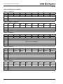
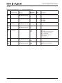
Input and Output Assemblies
Table 7-1: Output 20
Bit 7
Bit 6
Bit 5
Bit 4
Bit 3
Byte 0
Bit 2
Bit 1
FaultReset
Bit 0
RunFwd
Byte 1
Byte 2
Speed Reference (Low Byte)
Byte 3
Speed Reference (High Byte)
Table 7-2: Output 21 (Default)
Bit 7
Byte 0
Bit 6
Bit 5
NetRef
NetCtrl
Bit 4
Bit 3
Bit 2
Bit 1
Bit 0
FaultReset
RunRev
RunFwd
Bit 2
Bit 1
Bit 0
FaultReset
RunRev
RunFwd
Bit 2
Bit 1
Bit 0
FaultReset
RunRev
RunFwd
Bit 1
Bit 0
Byte 1
Byte 2
Speed Reference (Low Byte)
Byte 3
Speed Reference (High Byte)
Table 7-3: Output 23
Bit 7
Byte 0
Bit 6
Bit 5
NetRef
NetCtrl
Bit 4
Bit 3
Byte 1
Byte 2
Speed Reference (Low Byte)
Byte 3
Speed Reference (High Byte)
Byte 4
Torque Reference (Low Byte)
Byte 5
Torque Reference (High Byte)
Table 7-4: Output 25
Bit 7
Byte 0
Bit 6
Bit 5
NetRef
NetCtrl
Bit 4
Bit 3
Byte 1
Byte 2
Speed Reference (Low Byte)
Byte 3
Speed Reference (High Byte)
Byte 4
Process Reference (Low Byte)
Byte 5
Process Reference (High Byte)
Table 7-5: Input 70
Bit 7
Bit 6
Bit 5
Bit 4
Bit 3
Byte 0
Bit 2
Running1
Faulted
Byte 1
Byte 2
Speed Actual (Low Byte)
Byte 3
Speed Actual (High Byte)
7-2
For more information visit: www.eatonelectrical.com
MN04003005E
DeviceNet Option Board User Manual
March 2004
Table 7-6: Input 71 (Default)
Bit 7
Byte 0
Bit 6
Bit 5
Bit 4
AtReference RefFromNet CtrlFromNet Ready
Bit 3
Bit 2
Bit 1
Bit 0
Running2
Running1
Warning
Faulted
Bit 3
Bit 2
Bit 1
Bit 0
Running2
Running1
Warning
Faulted
Bit 3
Bit 2
Bit 1
Bit 0
Running2
Running1
Warning
Faulted
Byte 1
Drive State
Byte 2
Speed Actual (Low Byte)
Byte 3
Speed Actual (High Byte)
Table 7-7: Input 73
Bit 7
Byte 0
Bit 6
Bit 5
Bit 4
AtReference RefFromNet CtrlFromNet Ready
Byte 1
Drive State
Byte 2
Speed Actual (Low Byte)
Byte 3
Speed Actual (High Byte)
Byte 4
Torque Actual (Low Byte)
Byte 5
Torque Actual (High Byte)
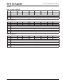
Table 7-8: Input 75
Bit 7
Byte 0
Bit 6
Bit 5
Bit 4
AtReference RefFromNet CtrlFromNet Ready
Byte 1
Drive State
Byte 2
Speed Actual (Low Byte)
Byte 3
Speed Actual (High Byte)
Byte 4
Process Actual (Low Byte)
Byte 5
Process Actual (High Byte)
MN04003005E
For more information visit: www.eatonelectrical.com
7-3
DeviceNet Option Board User Manual
March 2004
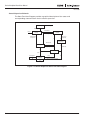
Control Supervisor Behavior
The State Transition Diagram provides a graphical description of the states and
corresponding state transitions for the control supervisor.
NonExist
Power_Off
Power_On
DriveFault
Reset
Faulted
Startup
Fault_Reset
Initialization
Complete
Fault_Stop
Complete
Fault_Stop
DriveFault
Ready
Stop_Complete
DriveFault
Stopping
Run
ChangeDir
Stop
Enabled
DriveFault OR SafeFault
SafeChange
Figure 7-2: Control Supervisor State Transition Diagram
7-4
For more information visit: www.eatonelectrical.com
MN04003005E
DeviceNet Option Board User Manual
March 2004
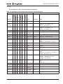
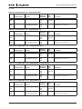
Control Supervisor State Transition Diagram Explanation
Table 7-9: Explanation of the Control Supervisor State Transition Diagram
RevMode
FwdMode
IdleMode
Run2Var
Results
Run1Var
Old State
CtrlFromNet
Input Conditions
Event
New State
Action
x
x
x
x
x
x
x
Power_Off
NonExist
x
(except
NonExist)
x
x
x
x
x
x
Reset
Startup
Faulted : = 0; Ready : = 0
FwdMode : = 0; RevMode : = 0
Run1Var : = 0; Run2Var : = 0
NonExist
x
x
x
x
x
x
Power_On
Startup
Faulted : = 0; Ready : = 0
FwdMode : = 0; RevMode : = 0
Run1Var : = 0; Run2Var : = 0
Startup
x
x
x
x
x
x
DriveFault
Faulted
Faulted : = 1; FaultCode : = x
Startup
x
x
x
x
x
x
Initialization Ready
Complete
Ready : = 1
Ready
x
x
x
x
x
x
DriveFault
Faulted
Faulted : = 1; FaultCode : = x; Ready : = 0
Ready
1
1
0
0
x
x
Run (Fwd)
Enabled
FwdMode : = 1 (Start Forward)
Ready
1
0
1
0
x
x
Run (Rev)
Enabled
RevMode : = 1 (Start Reverse)
Enabled
x
x
x
x
x
x
DriveFault
Fault_Stop
Faulted : = 1; FaultCode : = x (Initiate Faulted
Stop)
FwdMode : = 0; RevMode : = 0; Ready : = 0
Enabled
1
0
0
x
x
x
Stop
Stopping
(Initiate Stop)
Enabled
1
1
0
0
0
1
ChangeDir
(Fwd)
Enabled
FwdMode : = 1; RevMode : = 0 (Change to
Forward)
Enabled
1
0
1
0
1
0
ChangeDir
(Rev)
Enabled
FwdMode : = 0; RevMode : = 1 (Change to
Reverse)
Enabled
1
x
x
x
x
x
SafeFault
Fault_Stop
Faulted : = 1; FaultCode : = x (Initiate Faulted
Stop)
FwdMode : = 0; RevMode : = 0; Ready : = 0
Run1Var : = 0; Run2Var : = 0
Enabled
1
x
x
x
x
x
SafeChange Enabled
FwdMode : = Run1Var : = NOT PresetDir
RevMode : = Run2Var : = PresetDir
SpeedRef : = PresetSpeed
TorqueRef : = PresetTorque
Stopping
x
x
x
x
x
x
DriveFault
Fault_Stop
Faulted : = 1; FaultCode : = x (Initiate Faulted
Stop)
Ready : = 0
Stopping
1
1
0
0
x
x
Run (Fwd)
Enabled
FwdMode : = 1 (Start Forward)
RevMode : = 1 (Start Reverse)
Stopping
1
0
1
0
x
x
Run (Rev)
Enabled
Stopping
x
0
0
x
x
x
Stop_
Complete
Ready
Fault_Stop x
x
x
x
x
x
Fault_Stop
Complete
Faulted
Faulted
x
x
x
x
x
Fault_Reset
Ready
MN04003005E
x
Faulted : = 0; Ready : = 1
For more information visit: www.eatonelectrical.com
7-5
DeviceNet Option Board User Manual
March 2004
Start Forward, Start Reverse, Change to Forward, Change to Reverse, and Stop (Not Faulted
Stop) are static outputs of the Control Supervisor state machine. They are commands to the
drive when CtrlFromNet = 1. When CtrlFromNet = 0, control commands are from another
source.
Other Logic Equations
RefFromNet = (NetRef) AND (EnableFieldbus)
IF (RefFromNet)
{
(Write reference frequency or torque to the drive whenever SpeedRef or
TorqueRef are written)
}
When performing changes to achieve programmed Safe State:
1. Run/Stop/Direction can be changed because CtrlFromNet must equal 1 when in the
Enabled State
2. Reference in the drive can be changed to PresetSpeed or PresetTorque only if
(RefFromNet = 1)
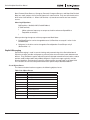
Explicit Messaging
Explicit Messaging is used in commissioning and parametrizing of the DeviceNet board.
Explicit messages provide multipurpose, point-to-point communication paths between two
devices. They provide the typical request/response-oriented network communication used to
perform node configuration and problem diagnosis. Explicit messages typically use low
priority identifiers and contain the specific meaning of the message right in the data field.
This includes the service to be performed and the specific object attribute address.
List of Object Classes
The Communication Interface supports the following object classes:
Table 7-10: Object Classes
7-6
Class
Object
0x01
Identity
0x02
Message Router
0x03
DeviceNet
0x04
Assembly
0x05
DeviceNet Connection
0x28
Motor Data
0x29
Control Supervisor
0x2A
AC/DC Drive
0xA0
Parameter
0xAA
Monitoring Data
For more information visit: www.eatonelectrical.com
MN04003005E
DeviceNet Option Board User Manual
March 2004
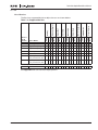
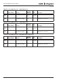
List of Services
The Services supported by these object classes are shown below.
Other Objects
Y
Y
Inst
Y
Class
Y
Inst
Class
AC/DC Drive
Control Supervisor
Y
Inst
Class
Y
Y
0E
Get_Attribute_Single
10
Set_Attribute_Single
Y
14
Error Response
Y
18
Get Member
Y
4B
Allocate_Master/
Slave_Connection_Set
Y
4C
Release_Master/
Slave_Connection_Set
Y
Y
Y
Class
Y
Inst
Y
Motor Data
Connection
Y
Inst
Class
Inst
Class
Assembly
DeviceNet
Inst
Class
Reset (Type 0, 1)
Inst
05
Class
Service Name
Inst
Service
Code
(in hex)
Class
Identity
Message Router
Table 7-11: Supported Services
Y
Y
Y
Y
Y
Y
Y
Y
Y
Y
Y
Y
Y
Y
Y
Y
Y
Y
Y
Y
Y
Y
Y
Y
Y
Y
Y
Y
Y
Y
Y
Y
Y
Y
Y
Y
Y
Y
Y
Y
Y
Y
Y
Y
Y
Y
Y
Vendor Specific Services
47
CH Get Member
Y
Y
Y
See Appendix B for the Interface Object profiles.
MN04003005E
For more information visit: www.eatonelectrical.com
7-7
DeviceNet Option Board User Manual
March 2004
List of Data Types
The attribute list that follows includes information on the Data Type of each attribute. The
following tables explain the Data, Structure and Array Type codes used in the Data Type
column.
Table 7-12: Elementary Data Types
Data Type Name
Data Type Code
(in hex)
Data Type Description
BOOL
C1
Logical Boolean with values TRUE and FALSE
SINT
C2
Signed 8-bit integer value
INT
C3
Signed 16-bit integer value
USINT
C6
Unsigned 8-bit integer value
UINT
C7
Unsigned 16-bit integer value
UDINT
C8
Unsigned 32-bit integer value
BYTE
D1
bit string – 8-bits
WORD
D2
bit string – 16-bits
SHORT_STRING
DA
character sting (1 byte per character, 1 byte length
indicator)
Table 7-13: Constructed Data Types
7-8
Type Code
Description
A1
Abbreviated array type encoding
A2
Formal structure type encoding
For more information visit: www.eatonelectrical.com
MN04003005E
DeviceNet Option Board User Manual
March 2004
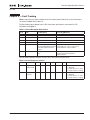
Reset Service
The following table lists the different types of resets supported by the Identity Object.
Resetting the OPTC7 interface to its out-of-box configuration will set ALL attributes to their
default values and change the response of the drive to a loss of communications with the
OPTC7. The device will have to be re-configured for your application before resuming normal
operation.
Resetting the inverter to its out-of-box configuration will set ALL inverter parameters to their
default values. Before restarting the inverter, you must verify that it is properly configured for
your application.
Table 7-14: Inverter Configuration
MN04003005E
Value:
Type of Reset:
0
Emulate as closely as possible the cycling of power to
the OPTC7 DeviceNet Interface. This value is the default
if this parameter is omitted. The drive shall be stopped
if it is running.
1
Return the OPTC7 DeviceNet Interface AND the Drive as
closely as possible to the out-of-box (factory default)
configuration, then emulate cycling of power as closely
as possible. The Drive shall be stopped if it is running.
For more information visit: www.eatonelectrical.com
7-9
DeviceNet Option Board User Manual
March 2004
7-10
For more information visit: www.eatonelectrical.com
MN04003005E
DeviceNet Option Board User Manual
March 2004
Chapter 8 — Fault Tracking
Table 8-1 presents the faults related to the DeviceNet Option Board. For more information,
see also the 9000X User’s Manual.
The DeviceNet Option Board status LEDs have been described in more detail in LED
Indications on Page 4-2.
Table 8-1: DeviceNet Option Board Faults
Fault
Code
Fault
Possible Cause
Correcting Measures
37
Device change
Option board changed.
Reset.
38
Device added
Option board added.
Reset.
39
Device removed
Option board removed.
Reset.
40
Device unknown
Unknown option board.
53
Fieldbus fault
The data connection between Check the installation.
the DeviceNet Master and the If installation is correct contact your
DeviceNet Option Board is
Cutler-Hammer representative.
broken.
54
Slot fault
Defective option board or
slot.
Check the board and slot.
Contact your Cutler-Hammer
representative.
You can define with parameters how the drive will react to certain faults:
Table 8-2: Drive Responses to Faults
MN04003005E
Code
Parameter
Min
Max
P2.7.22
Response to
fieldbus fault
0
P2.7.23
Response to
slot fault
0
Unit
Step
Default
ID
Note
3
1
0
733
0 = No response
1 = Warning
2 = Fault, stop acc. to 2.4.7
3 = Fault, stop by coasting
3
1
0
734
0 = No response
1 = Warning
2 = Fault, stop acc. to 2.4.7
3 = Fault, stop by coasting
For more information visit: www.eatonelectrical.com
8-1
DeviceNet Option Board User Manual
March 2004
8-2
For more information visit: www.eatonelectrical.com
MN04003005E
DeviceNet Option Board User Manual
March 2004
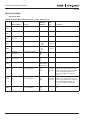
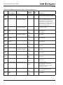
Appendix A — DeviceNet Interface Errors
The OPTC7 DeviceNet interface records the following events in the Event List FIFO:
Table A-1: Event List
Event Name
Event
Code
Event Description
No event
0x00
Default value in EventList entries.
Drive Communication Error
0x01
Inverter interface communication error with the drive.
I/O Connection Timeout – Fault_Stop
0x02
Control Supervisor transitions to Fault_Stop.
I/O Connection Timeout – No Action
0x03
Control Supervisor remains in Enabled State. Hold last speed
I/O Connection Timeout – Preset Direction
and Speed
0x04
Control Supervisor remains in Enabled State. Run at preset
direction and speed.
Explicit Connection Timeout – Fault_Stop
0x05
Control Supervisor transitions to Fault_Stop.
Explicit Connection Timeout – No Action
0x06
Control Supervisor remains in Enabled State. Hold last speed.
Explicit Connection Timeout – Preset
Direction and Speed
0x07
Control Supervisor remains in Enabled State. Run at preset
direction and speed.
Low DeviceNet Voltage
0x08
Connection timeout may occur next.
Bus Off
0x09
Connection timeout may occur next.
CAN Overrun
0x0C
Connection timeout may occur next.
Configuration Consistency Value (CRC)
mismatch
0x0E
The device’s configuration is incorrect or incomplete. Major
Recoverable Fault. An Identity Reset type 1 is needed for
recovery.
Microprocessor watchdog timeout
0x0F
The device detected a serious problem with itself. Major
Unrecoverable Fault.
Received explicit message is too big
0x10
Message is ignored.
Received IO message is too big
0x11
Message is ignored.
Parameter Range Error
0x12
An out-of-range parameter value exists in the drive.
I/O Connection Released – Fault_Stop
0x14
Control Supervisor transitions to Fault_Stop.
I/O Connection Released – No Action
0x15
Control Supervisor remains in Enabled State. Hold last speed.
I/O Connection Released – Preset Direction
and Speed
0x16
Control Supervisor remains in Enabled State. Run at preset
direction and speed.
Receive_Idle – Fault_Stop
0x17
Control Supervisor transitions to Fault_Stop.
Receive_Idle – No Action
0x18
Control Supervisor remains in Enabled State. Hold last speed.
Receive_Idle – Preset Direction and Speed
0x19
Control Supervisor remains in Enabled State. Run at preset
direction and speed.
Explicit Connection Released – Fault_Stop
0x1A
Control Supervisor transitions to Fault_Stop.
Explicit Connection Released – No Action
0x1B
Control Supervisor remains in Enabled State. Hold last speed.
Explicit Connection Released – Preset
Direction and Speed
0x1C
Control Supervisor remains in Enabled State. Run at preset
direction and speed.
MN04003005E
For more information visit: www.eatonelectrical.com
A-1
DeviceNet Option Board User Manual
March 2004
Table A-1: Event List, continued
Event Name
Event
Code
Event Description
Connection unable to read message
0x21
Error detected by connection object code.
Connection unable to send message
0x22
Error detected by connection object code.
Consumer unable to read message
0x23
Error detected by connection object code.
Producer unable to send message
0x24
Error detected by connection object code.
Producer unable to send buffer
0x25
Error detected by connection object code.
Producer unable to send acknowledgment
0x26
Error detected by connection object code.
Unexpected notification that message was
sent
0x27
Error detected by connection object code.
Explicit reply is too big
0x31
Error detected by connection object code.
First fragment of an IO message is too big
0x34
Error detected by connection object code.
Reassembled IO message is too big
0x35
Error detected by connection object code.
IO message is too big for producer
0x36
Error detected by connection object code.
IO/Explicit message is too big for producer
0x37
Error detected by connection object code.
A-2
For more information visit: www.eatonelectrical.com
MN04003005E
DeviceNet Option Board User Manual
March 2004
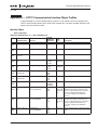
Appendix B — OPTC7 Communication Interface Object Profiles
In the following list, names followed by an asterisk (*) are stored in the non-volatile of the
OPTC7 or drive and maintain their values after a power loss. All other settable attributes will
power up at their default values.
Identity Object
Class Code 0x01
Table B-1: Identity Class (1) — Class Attributes (0)
Default,
Minimum,
Maximum
#
Attribute Name
Services
1
0x01
Revision
Get_Attribute_Single
2
0x02
Max Instance
Get_Attribute_Single
3
0x03
Number of
Instances
Get_Attribute_Single
4
0x04
Optional attribute
list
Get_Attribute_Single
5
0x05
Optional service
list
Get_Attribute_Single
6
0x06
Max Class
Attribute ID
Get_Attribute_Single
7
0x07
Max Instance
Attribute ID
Get_Attribute_Single
176
0xB0
Object Name
Get_Attribute_Single
180
0xB4
Class Attribute
List
Get Member,
CH_Get_Member
186
0xBA
Instance Attribute Get Member,
List
CH_Get_Member
N/A
N/A
N/A
190
0xBE
Instance ID List
N/A
N/A
N/A
MN04003005E
Get Member,
CH_Get_Member
1
1
1
1
1
1
1
1
1
{1,176}
{1,176}
{1,176}
{1,16}
{1,16}
{1,16}
190
190
190
176
176
176
"Identity"
"Identity"
"Identity"
N/A
N/A
N/A
Data
Type
Description
C7
Revision of this object
C7
C7
A2 04 C7
A1 01 C7
A2 04 C7
A1 01 C7
C7
C7
DA
ASCII Name for the object Class
A1 08 A2
06 C7 DA
DA A1 01
C6
Each Element describes a class
attribute. The Array’s elements are
structs as described in the semantics
section. Individual elements are
accessed using the Get Member
service.
A1 08 A2 Each Element describes an instance
06 C7 DA attribute. The Array’s elements are
DA A1 01 structs as described in the semantics
C6
section. Individual elements are
accessed using the Get Member
service.
A1 01 C7 Array of instance IDs supported by this
class
For more information visit: www.eatonelectrical.com
B-1
DeviceNet Option Board User Manual
March 2004
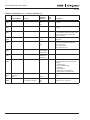
Table B-2: Identity Class (1) — Instance Attributes (1)
Default,
Minimum,
Maximum
#
Attribute Name
Services
1
0x01
Vendor Id
Get_Attribute_Single
2
0x02
Device Type
Get_Attribute_Single
3
0x03
Product Code
Get_Attribute_Single
4
0x04
5
0x05
Revision
Get_Attribute_Single
Status
Get_Attribute_Single
6
0x06
Serial Number
Get_Attribute_Single
7
0x07
Product Name
Get_Attribute_Single
8
0x08
State
Get_Attribute_Single
9
0x09
Configuration
Consistency
Value *
User Label *
Get_Attribute_Single
176
0xB0
B-2
Get_Attribute_Single,
Set_Attribute_Single
Data
Type
Description
443
443
443
2
2
2
1
1
1
C7
Identification of each vendor by
number
C7
Indication of the general type of
product
C7
{1,11} {1,11}
{1,11}
N/A
0
255
A2 02 C6
C6
D2
N/A
0x30940000
0x37FFFFFF
"NXOPTC7"
"NXOPTC7"
"NXOPTC7"
N/A
0
5
C8
This is a code assigned by the vendor
to describe the device. Product code
determined by interrogating the
connected drive.
Revision of the item the Identity Object
represents
Summary Status of the Device.
Defined in ODVA DeviceNet spec.
Bit 5 = User fault
Bit 6 = Node fault
Bit 7 = System fault
Serial Number of the device
DA
Human readable identification
C6
N/A
0
65535
N/A
N/A
N/A
C7
Present state of the device as
represented by the state transition
diagram.
0 = Nonexistent
1 = Device Self Testing
2 = Standby
3 = Operational
4 = Major Recoverable Fault
5 = Major Unrecoverable Fault
Contents identify configuration of
device
DA
For more information visit: www.eatonelectrical.com
User Supplied name for the Instance.
Maximum of 8 characters
MN04003005E
DeviceNet Option Board User Manual
March 2004
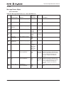
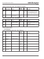
Message Router Object
Class Code 0x02
Table B-3: Message Router Class (2) — Class Attributes (0)
Default,
Minimum,
Maximum
#
Attribute Name
Services
1
0x01
Revision
Get_Attribute_Single
2
0x02
Max Instance
Get_Attribute_Single
3
0x03
Number of
Instances
Get_Attribute_Single
4
0x04
Optional attribute
list
Get_Attribute_Single
5
0x05
Optional service
list
Get_Attribute_Single
6
0x06
Max Class
Attribute ID
Get_Attribute_Single
7
0x07
Max Instance
Attribute ID
Get_Attribute_Single
176
0xB0
Object Name
Get_Attribute_Single
180
0xB4
Class Attribute
List
Get Member,
CH_Get_Member
186
0xBA
Instance Attribute Get Member,
List
CH_Get_Member
N/A
N/A
N/A
190
0xBE
Instance ID List
N/A
N/A
N/A
MN04003005E
Get Member,
CH_Get_Member
1
1
1
1
1
1
1
1
1
{1,176}
{1,176}
{1,176}
{1,16}
{1,16}
{1,16}
190
190
190
176
176
176
"Message
Router"
"Message
Router"
"Message
Router"
N/A
N/A
N/A
Data
Type
Description
C7
Revision of this object
C7
C7
A2 04 C7
A1 01 C7
A2 04 C7
A1 01 C7
C7
C7
DA
ASCII Name for the object Class
A1 08 A2
06 C7 DA
DA A1 01
C6
Each Element describes a class
attribute. The Array’s elements are
structs as described in the semantics
section. Individual elements are
accessed using the Get Member
service.
A1 08 A2 Each Element describes an instance
06 C7 DA attribute. The Array’s elements are
DA A1 01 structs as described in the semantics
C6
section. Individual elements are
accessed using the Get Member
service.
A1 01 C7 Array of instance IDs supported by this
class
For more information visit: www.eatonelectrical.com
B-3
DeviceNet Option Board User Manual
March 2004
Table B-4: Message Router Class (2) — Instance Attributes (1)
Default,
Minimum,
Maximum
#
Attribute Name
Services
1
0x01
Object List
Get_Attribute_Single
176
0xB0
User Label *
Get_Attribute_Single,
Set_Attribute_Single
N/A
N/A
N/A
N/A
N/A
N/A
Data
Type
Description
A2 04 C7
A1 01 C7
DA
User Supplied name for the Instance.
Maximum of 8 characters
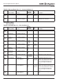
DeviceNet Object
Class Code 0x03
Table B-5: DeviceNet Class (3) — Class Attributes (0)
Default,
Minimum,
Maximum
#
Attribute Name
Services
1
0x01
Revision
Get_Attribute_Single
2
0x02
Max Instance
Get_Attribute_Single
3
0x03
Number of
Instances
Get_Attribute_Single
4
0x04
Optional attribute
list
Get_Attribute_Single
5
0x05
Optional service
list
Get_Attribute_Single
6
0x06
Max Class
Attribute ID
Get_Attribute_Single
7
0x07
Max Instance
Attribute ID
Get_Attribute_Single
176
0xB0
Object Name
Get_Attribute_Single
180
0xB4
Class Attribute
List
Get Member,
CH_Get_Member
186
0xBA
Instance Attribute Get Member,
List
CH_Get_Member
N/A
N/A
N/A
190
0xBE
Instance ID List
N/A
N/A
N/A
B-4
Get Member,
CH_Get_Member
2
2
2
1
1
1
1
1
1
{1,176}
{1,176}
{1,176}
{1,16}
{1,16}
{1,16}
190
190
190
176
176
176
"DeviceNet"
"DeviceNet"
"DeviceNet"
N/A
N/A
N/A
Data
Type
Description
C7
Revision of this object
C7
C7
A2 04 C7
A1 01 C7
A2 04 C7
A1 01 C7
C7
C7
DA
ASCII Name for the object Class
A1 08 A2
06 C7 DA
DA A1 01
C6
Each Element describes a class
attribute. The Array’s elements are
structs as described in the semantics
section. Individual elements are
accessed using the Get Member
service.
A1 08 A2 Each Element describes an instance
06 C7 DA attribute. The Array’s elements are
DA A1 01 structs as described in the semantics
C6
section. Individual elements are
accessed using the Get Member
service.
A1 01 C7 Array of instance IDs supported by this
class
For more information visit: www.eatonelectrical.com
MN04003005E
DeviceNet Option Board User Manual
March 2004
Table B-6: DeviceNet Class (3) — Instance Attributes (1)
Default,
Minimum,
Maximum
#
Attribute Name
Services
1
0x01
MAC ID *
Get_Attribute_Single,
Set_Attribute_Single
0x02
Baud Rate *
Get_Attribute_Single,
Set_Attribute_Single
3
0x03
BOI [Bus Off
Interrupt]
Get_Attribute_Single,
Set_Attribute_Single
4
0x04
Bus-off Counter
Get_Attribute_Single,
Set_Attribute_Single
5
0x05
Allocation
Information
Get_Attribute_Single
100
0x64
Bus-off Separation Get_Attribute_Single,
Set_Attribute_Single
176
0xB0
User Label *
MN04003005E
Get_Attribute_Single,
Set_Attribute_Single
Data
Type
Description
63
0
63
0
0
2
C6
Node Address.
C6
The baud rate of the device.
00 = 125K
01 = 250K
02 = 500K
1
0
1
0
0
255
N/A
N/A
N/A
C1
50
0
255
N/A
N/A
N/A
C6
C6
A2 02 D1
C6
DA
For more information visit: www.eatonelectrical.com
Allocation Choice Master’s Mac ID
Struct of:
BYTE: Allocation Choice byte
Bit 0 = explicit messaging
Bit 1 = Polled I/O
USINT: Master’s Mac ID
0 – 63 = valid
255 = unallocated
User Supplied name for the Instance.
Maximum of 8 characters
B-5
DeviceNet Option Board User Manual
March 2004
Assembly Object
Class Code 0x04
Table B-7: Assembly Class (4) — Class Attributes (0)
Default,
Minimum,
Maximum
#
Attribute Name
Services
1
0x01
Revision
Get_Attribute_Single
2
0x02
Max Instance
Get_Attribute_Single
3
0x03
Number of
Instances
Get_Attribute_Single
4
0x04
Optional attribute
list
Get_Attribute_Single
5
0x05
Optional service
list
Get_Attribute_Single
6
0x06
Max Class
Attribute ID
Get_Attribute_Single
7
0x07
Max Instance
Attribute ID
Get_Attribute_Single
176
0xB
Object Name
Get_Attribute_Single
180
0xB4
Class Attribute
List
Get Member,
CH_Get_Member
186
0xBA
Instance Attribute Get Member,
List
CH_Get_Member
N/A
N/A
N/A
190
0xBE
Instance ID List
N/A
N/A
N/A
B-6
Get Member,
CH_Get_Member
2
2
2
75
75
75
8
8
8
{1,176}
{1,176}
{1,176}
{1,16}
{1,16}
{1,16}
190
190
190
176
176
176
"Assembly"
"Assembly"
"Assembly"
N/A
N/A
N/A
Data
Type
Description
C7
Revision of this object
C7
C7
A2 04 C7
A1 01 C7
A2 04 C7
A1 01 C7
C7
C7
DA
ASCII Name for the object Class
A1 08 A2
06 C7 DA
DA A1 01
C6
Each Element describes a class
attribute. The Array’s elements are
structs as described in the semantics
section. Individual elements are
accessed using the Get Member
service.
A1 08 A2 Each Element describes an instance
06 C7 DA attribute. The Array’s elements are
DA A1 01 structs as described in the semantics
C6
section. Individual elements are
accessed using the Get Member
service.
A1 01 C7 Array of instance IDs supported by this
class
For more information visit: www.eatonelectrical.com
MN04003005E
DeviceNet Option Board User Manual
March 2004
Table B-8: Assembly Class (4) — Basic Control (20)
Default,
Minimum,
Maximum
#
Attribute Name
Services
3
0x03
Data
Get_Attribute_Single
176
0xB0
User Label *
Get_Attribute_Single,
Set_Attribute_Single
N/A
N/A
N/A
N/A
N/A
N/A
Data
Type
A2 05 A1
01 C1 D1
C3
DA
Description
User Supplied name for the Instance.
Maximum of 8 characters
Table B-9: Assembly Class (4) — Speed Control (21)
Default,
Minimum,
Maximum
#
Attribute Name
Services
3
0x03
Data
Get_Attribute_Single
176
0xB0
User Label *
Get_Attribute_Single,
Set_Attribute_Single
N/A
N/A
N/A
N/A
N/A
N/A
Data
Type
A2 05 A1
01 C1 D1
C3
DA
Description
User Supplied name for the Instance.
Maximum of 8 characters
Table B-10: Assembly Class (4) — Torque Control (23)
Default,
Minimum,
Maximum
#
Attribute Name
Services
3
0x03
Data
Get_Attribute_Single
176
0xB0
User Label *
Get_Attribute_Single,
Set_Attribute_Single
N/A
N/A
N/A
N/A
N/A
N/A
Data
Type
A2 05 A1
01 C1 D1
C3
DA
Description
User Supplied name for the Instance.
Maximum of 8 characters
Table B-11: Assembly Class (4) — Extended Process Control (25)
Default,
Minimum,
Maximum
#
Attribute Name
Services
3
0x03
Data
Get_Attribute_Single
176
0xB0
User Label *
Get_Attribute_Single,
Set_Attribute_Single
N/A
N/A
N/A
N/A
N/A
N/A
Data
Type
A2 05 A1
01 C1 D1
C3
DA
Description
User Supplied name for the Instance.
Maximum of 8 characters
Table B-12: Assembly Class (4) — Basic Status (70)
Default,
Minimum,
Maximum
#
Attribute Name
Services
3
0x03
Data
Get_Attribute_Single
176
0xB0
User Label *
Get_Attribute_Single,
Set_Attribute_Single
MN04003005E
N/A
N/A
N/A
N/A
N/A
N/A
Data
Type
A2 05 A1
01 C1 D1
C3
DA
For more information visit: www.eatonelectrical.com
Description
User Supplied name for the Instance.
Maximum of 8 characters
B-7
DeviceNet Option Board User Manual
March 2004
Table B-13: Assembly Class (4) — Speed Status (71)
Default,
Minimum,
Maximum
#
Attribute Name
Services
3
0x03
Data
Get_Attribute_Single
176
0xB0
User Label *
Get_Attribute_Single,
Set_Attribute_Single
N/A
N/A
N/A
N/A
N/A
N/A
Data
Type
A2 05 A1
01 C1 D1
C3
DA
Description
User Supplied name for the Instance.
Maximum of 8 characters
Table B-14: Assembly Class (4) — Torque Status (73)
Default,
Minimum,
Maximum
#
Attribute Name
Services
3
0x03
Data
Get_Attribute_Single
176
0xB0
User Label *
Get_Attribute_Single,
Set_Attribute_Single
N/A
N/A
N/A
N/A
N/A
N/A
Data
Type
A2 05 A1
01 C1 D1
C3
DA
Description
User Supplied name for the Instance.
Maximum of 8 characters
Table B-15: Assembly Class (4) — Extended Process Control (75)
Default,
Minimum,
Maximum
#
Attribute Name
Services
3
0x03
Data
Get_Attribute_Single
176
0xB0
User Label *
Get_Attribute_Single,
Set_Attribute_Single
B-8
N/A
N/A
N/A
N/A
N/A
N/A
Data
Type
A2 05 A1
01 C1 D1
C3
DA
For more information visit: www.eatonelectrical.com
Description
User Supplied name for the Instance.
Maximum of 8 characters
MN04003005E
DeviceNet Option Board User Manual
March 2004
DeviceNet Connection Object
Class Code 0x05
Table B-16: DeviceNet Connection Class (5) — Class Attributes (0)
Default,
Minimum,
Maximum
#
Attribute Name
Services
1
0x01
Revision
Get_Attribute_Single
2
0x02
Max Instance
Get_Attribute_Single
3
0x03
Number of
Instances
Get_Attribute_Single
4
0x04
Optional attribute
list
Get_Attribute_Single
5
0x05
Optional service
list
Get_Attribute_Single
6
0x06
Max Class
Attribute ID
Get_Attribute_Single
7
0x07
Max Instance
Attribute ID
Get_Attribute_Single
176
0xB0
Object Name
Get_Attribute_Single
180
0xB4
Class Attribute
List
Get Member,
CH_Get_Member
186
0xBA
Instance Attribute Get Member,
List
CH_Get_Member
N/A
N/A
N/A
190
0xBE
Instance ID List
N/A
N/A
N/A
MN04003005E
Get Member,
CH_Get_Member
1
1
1
2
2
2
2
2
2
{1,176}
{1,176}
{1,176}
{1,16}
{1,16}
{1,16}
190
190
190
176
176
176
"DeviceNet
Connection"
"DeviceNet
Connection"
"DeviceNet
Connection"
N/A
N/A
N/A
Data
Type
Description
C7
Revision of this object
C7
C7
A2 04 C7
A1 01 C7
A2 04 C7
A1 01 C7
C7
C7
DA
ASCII Name for the object Class
A1 08 A2
06 C7 DA
DA A1 01
C6
Each Element describes a class
attribute. The Array’s elements are
structs as described in the semantics
section. Individual elements are
accessed using the Get Member
service.
A1 08 A2 Each Element describes an instance
06 C7 DA attribute. The Array’s elements are
DA A1 01 structs as described in the semantics
C6
section. Individual elements are
accessed using the Get Member
service.
A1 01 C7 Array of instance IDs supported by this
class
For more information visit: www.eatonelectrical.com
B-9
DeviceNet Option Board User Manual
March 2004
Table B-17: DeviceNet Connection Class (5) — Explicit Connection Instance (1)
Default,
Minimum,
Maximum
#
Attribute Name
Services
1
0x01
State
Get_Attribute_Single
2
0x02
Instance Type
Get_Attribute_Single
3
0x03
Transport Class
Trigger
Get_Attribute_Single
4
0x04
Produced
Connection Id
Get_Attribute_Single
5
0x05
Consumed
Connection Id
Get_Attribute_Single
6
0x06
Initial Comm
Characteristics
Get_Attribute_Single
7
0x07
Produced
Connection Size
Get_Attribute_Single
8
0x08
Consumed
Connection Size
Get_Attribute_Single
9
0x09
Expected Packet
Rate
Get_Attribute_Single,
Set_Attribute_Single
12
0x0C
Watchdog
Timeout Action
Get_Attribute_Single,
Set_Attribute_Single
13
0x0D
Produced
Connection Path
Length
Produced
Connection Path
Get_Attribute_Single
Consumed
Connection Path
Length
Consumed
Connection Path
Get_Attribute_Single
User Label *
Get_Attribute_Single,
Set_Attribute_Single
14
0x0E
15
0x0F
16
0x10
176
0xB0
B-10
Get_Attribute_Single
Get_Attribute_Single
Data
Type
Description
0
0
5
0
0
0
0x83
0x83
0x83
N/A
0x403
0x5FB
N/A
0x404
0x5FC
0x21
0x21
0x21
41
41
41
41
41
41
2500
0
65535
1
1
3
C6
State of the object
C6
Indicates either I/O or messaging
connection
0 = Explicit
Defines Behavior of the connection
0
0
0
N/A
N/A
N/A
0
0
0
N/A
N/A
N/A
N/A
N/A
N/A
C7
D1
C7
Placed in CAN Identifier Field when
the Connection Transmits
C7
CAN Identifier Field value that denotes
message to be received
D1
Defines the Message Group(s) across
which productions and consumptions
associated with this
Maximum number of bytes
transmitted across this Connection
C7
C7
Maximum number of bytes received
across this Connection
C7
Defines timing associated with this
Connection
C6
Defines how to handle Inactivity/
Watchdog timeouts.
1 = Auto Delete
3 = Deferred Delete
An attempt to set this attribute to the
value 2 will result in an Invalid
Attribute Value error.
Number of bytes in the
produced_connection_path length
attribute
Application Obj. producing data on
this connection
A1 01 C6
C7
A1 01 C7
DA
For more information visit: www.eatonelectrical.com
Number of bytes in the
consumed_connection_path length
attribute
Specifies the Application Object(s)
that are to receive the data consumed
by this Connection Object
User Supplied name for the Instance.
Maximum of 8 characters
MN04003005E
DeviceNet Option Board User Manual
March 2004
Table B-18: DeviceNet Connection Class (5) — I/O Connection Instance (1)
Default,
Minimum,
Maximum
#
Attribute Name
Services
1
0x01
State
Get_Attribute_Single
2
0x02
Instance Type
Get_Attribute_Single
3
0x03
Transport Class
Trigger
Get_Attribute_Single
4
0x04
Produced
Connection Id
Get_Attribute_Single
5
0x05
Consumed
Connection Id
Get_Attribute_Single
6
0x06
Initial Comm
Characteristics
Get_Attribute_Single
7
0x07
Produced
Connection Size
Get_Attribute_Single
8
0x08
Consumed
Connection Size
Get_Attribute_Single
9
0x09
Expected Packet
Rate
Get_Attribute_Single,
Set_Attribute_Single
12
0x0C
Watchdog
Timeout Action
Get_Attribute_Single,
Set_Attribute_Single
13
0x0D
Produced
Connection Path
Length
Produced
Connection Path
Get_Attribute_Single
Consumed
Connection Path
Length
Consumed
Connection Path
Get_Attribute_Single
User Label *
Get_Attribute_Single,
Set_Attribute_Single
14
0x0E
15
0x0F
16
0x10
176
0xB0
MN04003005E
Get_Attribute_Single
Get_Attribute_Single
Data
Type
Description
0
0
4
1
1
1
0x83
0x83
0x83
N/A
0x3C0
0x3FF
N/A
0x405
0x5FD
1
1
1
4
0
6
4
0
6
0
0
65535
0
0
2
C6
State of the object
C6
Indicates either I/O or messaging
connection
1 = I/O
Defines Behavior of the connection
6
6
6
N/A
N/A
N/A
6
6
6
N/A
N/A
N/A
N/A
N/A
N/A
C7
D1
C7
Placed in CAN Identifier Field when
the Connection Transmits
C7
CAN Identifier Field value that denotes
message to be received
D1
Defines the Message Group(s) across
which productions and consumptions
associated with this
Maximum number of bytes
transmitted across this Connection
C7
C7
Maximum number of bytes received
across this Connection
C7
Defines timing associated with this
Connection
C6
Defines how to handle Inactivity/
Watchdog timeouts.
1 = Auto Delete
3 = Deferred Delete
An attempt to set this attribute to the
value 2 will result in an Invalid
Attribute Value error.
Number of bytes in the
produced_connection_path length
attribute
Application Obj. producing data on
this connection
A1 01 C6
C7
A1 01 C7
DA
For more information visit: www.eatonelectrical.com
Number of bytes in the
consumed_connection_path length
attribute
Specifies the Application Object(s)
that are to receive the data consumed
by this Connection Object
User Supplied name for the Instance.
Maximum of 8 characters
B-11
DeviceNet Option Board User Manual
March 2004
Motor Data Object
Class Code 0x28
Table B-19: Motor Data Object Class (40) — Class Attributes (0)
Default,
Minimum,
Maximum
#
Attribute Name
Services
1
0x01
Revision
Get_Attribute_Single
2
0x02
Max Instance
Get_Attribute_Single
3
0x03
Number of
Instances
Get_Attribute_Single
4
0x04
Optional attribute
list
Get_Attribute_Single
5
0x05
Optional service
list
Get_Attribute_Single
6
0x06
Max Class
Attribute ID
Get_Attribute_Single
7
0x07
Max Instance
Attribute ID
Get_Attribute_Single
176
0xB0
Object Name
Get_Attribute_Single
180
0xB4
Class Attribute
List
Get Member,
CH_Get_Member
186
0xBA
Instance Attribute Get Member,
List
CH_Get_Member
N/A
N/A
N/A
190
0xBE
Instance ID List
N/A
N/A
N/A
B-12
Get Member,
CH_Get_Member
1
1
1
1
1
1
1
1
1
{1,176}
{1,176}
{1,176}
{1,16}
{1,16}
{1,16}
190
190
190
176
176
176
"Motor Data"
"Motor Data"
"Motor Data"
N/A
N/A
N/A
Data
Type
Description
C7
Revision of this object
C7
C7
A2 04 C7
A1 01 C7
A2 04 C7
A1 01 C7
C7
C7
DA
ASCII Name for the object Class
A1 08 A2
06 C7 DA
DA A1 01
C6
Each Element describes a class
attribute. The Array’s elements are
structs as described in the semantics
section. Individual elements are
accessed using the Get Member
service.
A1 08 A2 Each Element describes an instance
06 C7 DA attribute. The Array’s elements are
DA A1 01 structs as described in the semantics
C6
section. Individual elements are
accessed using the Get Member
service.
A1 01 C7 Array of instance IDs supported by this
class
For more information visit: www.eatonelectrical.com
MN04003005E
DeviceNet Option Board User Manual
March 2004
Table B-20: Motor Data Object Class (40) — Instance Attributes (1)
Default,
Minimum,
Maximum
Data
Type
#
Attribute Name
Services
3
0x03
Motor Type
Get_Attribute_Single
7
7
7
C6
6
0x06
RatedCurrent
[100mA]
Get_Attribute_Single
C7
7
0x07
RatedVoltage[V]
Get_Attribute_Single
9
0x09
RatedFrequency
[Hz]
Get_Attribute_Single
12
0x0C
PoleCount[pairx2] Get_Attribute_Single
15
0x0F
BaseSpeed[RPM]
Get_Attribute_Single
176
0xB0
User Label *
Get_Attribute_Single,
Set_Attribute_Single
70
0
16000
230
180
690
50
30
500
4
2
16
1440
1
30000
N/A
N/A
N/A
MN04003005E
Description
Type of Motor Represented by This
Instance
0 = Non-standard motor
1 = PM DC Motor
2 = FC DC Motor
3 = PM Synchronous Motor
4 = FC Synchronous Motor
5 = Switched Reluctance Motor
6 = Wound Rotor Induction Motor
7 = Squirrel Cage Induction Motor
8 = Stepper Motor
9 = Sinusoidal PM BL Motor
10 = Trapezoidal PM BL Motor
Rated Stator Current
Units: [100mA]
C7
Rated Base Voltage
Units: [V]
C7
Rated Electrical Frequency
Units: [Hz]
C7
Number of poles in the motor
C7
Nominal speed at rated frequency
from nameplate
Units: [RPM]
User Supplied name for the Instance.
Maximum of 8 characters
DA
For more information visit: www.eatonelectrical.com
B-13
DeviceNet Option Board User Manual
March 2004
Control Supervisor Object
Class Code 0x29
Table B-21: Control Supervisor Object Class (41) — Class Attributes (0)
Default,
Minimum,
Maximum
#
Attribute Name
Services
1
0x01
Revision
Get_Attribute_Single
2
0x02
Max Instance
Get_Attribute_Single
3
0x03
Number of
Instances
Get_Attribute_Single
4
0x04
Optional attribute
list
Get_Attribute_Single
5
0x05
Optional service
list
Get_Attribute_Single
6
0x06
Max Class
Attribute ID
Get_Attribute_Single
7
0x07
Max Instance
Attribute ID
Get_Attribute_Single
176
0xB0
Object Name
Get_Attribute_Single
180
0xB4
Class Attribute
List
Get Member,
CH_Get_Member
186
0xBA
Instance Attribute Get Member,
List
CH_Get_Member
N/A
N/A
N/A
190
0xBE
Instance ID List
N/A
N/A
N/A
B-14
Get Member,
CH_Get_Member
1
1
1
1
1
1
1
1
1
{1,176}
{1,176}
{1,176}
{1,16}
{1,16}
{1,16}
190
190
190
176
176
176
"Control
Supervisor"
"Control
Supervisor"
"Control
Supervisor"
N/A
N/A
N/A
Data
Type
Description
C7
Revision of this object
C7
C7
A2 04 C7
A1 01 C7
A2 04 C7
A1 01 C7
C7
C7
DA
ASCII Name for the object Class
A1 08 A2
06 C7 DA
DA A1 01
C6
Each Element describes a class
attribute. The Array’s elements are
structs as described in the semantics
section. Individual elements are
accessed using the Get Member
service.
A1 08 A2 Each Element describes an instance
06 C7 DA attribute. The Array’s elements are
DA A1 01 structs as described in the semantics
C6
section. Individual elements are
accessed using the Get Member
service.
A1 01 C7 Array of instance Ids supported by this
class
For more information visit: www.eatonelectrical.com
MN04003005E
DeviceNet Option Board User Manual
March 2004
Table B-22: Control Supervisor Object Class (41) — Instance Attributes (1)
Default,
Minimum,
Maximum
Data
Type
Description
0
0
1
0
0
1
0
0
1
N/A
0
7
C1
Run Forward Request
C1
Run Reverse Request
C1
Requests Run/Stop control to be local
or from network
C6
N/A,
0
1
N/A,
0
1
N/A,
0
1
N/A,
0
1
N/A,
0
1
0
0
1
C1
Get_Attribute_Single
N/A,
0,
65535
C7
WarnCode
Get_Attribute_Single
N/A,
0,
65535
C7
CtrlFromNet
Get_Attribute_Single
N/A,
0
1
C1
State of Control Supervisor Instance
1 = Startup
2 = Not_Ready
3 = Ready
4 = Enabled
5 = Stopping
6 = Fault_Stop
7 = Faulted
Running Forward Status
0 = Other state
1 = Running Forward
Running Reverse Status
0 = Other state
1 = Running reverse
Ready to Accept a Run Event
0 = Other state
1 = Ready to accept a Run Event
Fault Occurred
0 = No faults present
1 = Fault occurred (latched)
Warning Present
0 = No warnings present
1 = Warning present (not latched)
Fault Reset Request
0 = No action
0 -> 1 = Fault reset request
1 = No action
If in Faulted state, FaultCode indicates
the fault that caused the transition to
Faulted state. If not in Faulted state,
FaultCode indicates the fault that
caused the last transition to Faulted
state. Fault codes are listed in
DeviceNet Volume II, section 6-29.6
If in Enabled state, WarnCode
indicates the lowest valued warning
that caused the Warning bit to be
TRUE. Warning codes are listed in
DeviceNet Volume II, section 6-29.6
Status of Run/Stop control source
0 = Control is local
1 = Control is from network
#
Attribute Name
Services
3
0x03
Run1
Get_Attribute_Single,
Set_Attribute_Single
4
0x04
Run2
Get_Attribute_Single,
Set_Attribute_Single
5
0x05
NetCtrl
Get_Attribute_Single,
Set_Attribute_Single
6
0x06
State
Get_Attribute_Single
7
0x07
Running1
Get_Attribute_Single
8
0x08
Running2
Get_Attribute_Single
9
0x09
Ready
Get_Attribute_Single
10
0x0A
Faulted
Get_Attribute_Single
11
0x0B
Warning
Get_Attribute_Single
12
0x0C
FaultRst
Get_Attribute_Single,
Set_Attribute_Single
13
0x0D
FaultCode
14
0x0E
15
0x0F
MN04003005E
C1
C1
C1
C1
C1
For more information visit: www.eatonelectrical.com
B-15
DeviceNet Option Board User Manual
March 2004
Table B-22: Control Supervisor Object Class (41) — Instance Attributes (1), continued
Default,
Minimum,
Maximum
Data
Type
#
Attribute Name
Services
16
0x10
DNFaultMode *
Get_Attribute_Single,
Set_Attribute_Single
0
0
2
C6
176
0xB0
User Label *
Get_Attribute_Single,
Set_Attribute_Single
N/A
N/A
N/A
DA
B-16
For more information visit: www.eatonelectrical.com
Description
Action on loss of DeviceNet
0 = Fault and Stop
1 = Ignore
2 = Use preset speed and direction
Note: Ignoring communication faults
may result in equipment damage,
personal injury or death. Ensure that
you understand how ignoring a
communication fault may affect the
operation of your system.
User Supplied name for the Instance.
Maximum of 8 characters
MN04003005E
DeviceNet Option Board User Manual
March 2004
AC/DC Drive Object
Class Code 0x2A
Table B-23: AC/DC Drive Object Class (42) — Class Attributes (0)
Default,
Minimum,
Maximum
#
Attribute Name
Services
1
0x01
Revision
Get_Attribute_Single
2
0x02
Max Instance
Get_Attribute_Single
3
0x03
Number of
Instances
Get_Attribute_Single
4
0x04
Optional attribute
list
Get_Attribute_Single
5
0x05
Optional service
list
Get_Attribute_Single
6
0x06
Max Class
Attribute ID
Get_Attribute_Single
7
0x07
Max Instance
Attribute ID
Get_Attribute_Single
176
0xB0
Object Name
Get_Attribute_Single
180
0xB4
Class Attribute
List
Get Member,
CH_Get_Member
186
0xBA
Instance Attribute Get Member,
List
CH_Get_Member
N/A
N/A
N/A
190
0xBE
Instance ID List
N/A
N/A
N/A
MN04003005E
Get Member,
CH_Get_Member
1
1
1
1
1
1
1
1
1
{1,176}
{1,176}
{1,176}
{1,16}
{1,16}
{1,16}
190
190
190
176
176
176
"AC\DC
Drive"
"AC\DC
Drive"
"AC\DC
Drive"
N/A
N/A
N/A
Data
Type
Description
C7
Revision of this object
C7
C7
A2 04 C7
A1 01 C7
A2 04 C7
A1 01 C7
C7
C7
DA
ASCII Name for the object Class
A1 08 A2
06 C7 DA
DA A1 01
C6
Each Element describes a class
attribute. The Array’s elements are
structs as described in the semantics
section. Individual elements are
accessed using the Get Member
service.
A1 08 A2 Each Element describes an instance
06 C7 DA attribute. The Array’s elements are
DA A1 01 structs as described in the semantics
C6
section. Individual elements are
accessed using the Get Member
service.
A1 01 C7 Array of instance IDs supported by this
class
For more information visit: www.eatonelectrical.com
B-17
DeviceNet Option Board User Manual
March 2004
Table B-24: AC/DC Drive Object Class (42) — Instance Attributes (1)
Default,
Minimum,
Maximum
#
Attribute Name
Services
3
0x03
AtReference
Get_Attribute_Single
4
0x04
NetRef
Get_Attribute_Single,
Set_Attribute_Single
6
0x06
DriveMode
7
0x07
Data
Type
Description
N/A
0
1
0
0
1
C1
1 = Drive actual at reference (speed or
torque reference) based on mode
C1
Get_Attribute_Single,
Set_Attribute_Single
1
1
3
C6
Requests torque or speed reference to
be local or from the network
0 = Set Reference not DN Control
1 = Set Reference at DN Control
Note that the actual status of torque or
speed reference is reflected in
attribute 29, RefFromNet
1 = Open loop speed (Frequency)
3 = Torque control
SpeedActual
[RPM]
Get_Attribute_Single
C3
8
0x08
SpeedRef[RPM]
Get_Attribute_Single,
Set_Attribute_Single
9
0x09
CurrentActual
[100 mA]
Get_Attribute_Single
10
0x0A
CurrentLimit
[100 mA]
Get_Attribute_Single
11
0x0B
TorqueActual[Nm] Get_Attribute_Single
12
0x0C
TorqueRef[Nm]
Get_Attribute_Single,
Set_Attribute_Single
15
0x0F
PowerActual[W]
Get_Attribute_Single
16
0x10
InputVoltage[V]
Get_Attribute_Single
17
0x11
OutputVoltage[V]
Get_Attribute_Single
18
0x12
AccelTime[64mS]
Get_Attribute_Single
N/A,
0
30000
1
1
30000
N/A,
0
32767
N/A,
0
32767
N/A,
0
32767
0
0
10000
N/A,
0
32767
N/A
180
690
N/A
0
690
47
1
46875
19
0x13
DecelTime[64mS]
Get_Attribute_Single
20
0x14
LowSpdLimit
[RPM]
Get_Attribute_Single
B-18
47
1
46875
0
0
30000
C3
Actual drive speed (best
approximation)
Units: RPM
Speed reference
Units: RPM
C3
Actual motor phase current
Units: 100 mA
C3
Motor phase current limit
Units: 100 mA
C3
Actual torque
Units: Nm
C3
Torque reference
Units: Nm
C3
Actual output power
Units: Watts
C3
Input Voltage
Units: Volts
C3
Output Voltage
Units: Volts
C7
Acceleration time
Time from 0 to HighSpdLimit
Units: mS / 64
Attribute 28 (TimeScale) defines
scaling factor as 64
Deceleration time
Time from HighSpdLimit to 0
Units: mS / 64
Minimum speed limit
Units: RPM
C7
C7
For more information visit: www.eatonelectrical.com
MN04003005E
DeviceNet Option Board User Manual
March 2004
Table B-24: AC/DC Drive Object Class (42) — Instance Attributes (1), continued
Default,
Minimum,
Maximum
#
Attribute Name
Services
21
0x15
HighSpdLimit
[RPM]
Get_Attribute_Single
29
0x1D
RefFromNet
Get_Attribute_Single
176
0xB0
User Label *
Get_Attribute_Single,
Set_Attribute_Single
1800
0
30000
N/A
0
1
N/A
N/A
N/A
Data
Type
Description
C7
Maximum speed limit
Units: RPM
C1
Status of torque/speed reference
0 = Local torque/speed reference
1 = DeviceNet torque/speed reference
User Supplied name for the Instance.
Maximum of 8 characters
DA
Parameter Object
Class Code 0xA0
Table B-25: Parameter Class (160) — Class Attributes (0)
Default,
Minimum,
Maximum
#
Attribute Name
Services
1
0x01
Revision
Get_Attribute_Single
2
0x02
Max Instance
Get_Attribute_Single
3
0x03
Number of
Instances
Get_Attribute_Single
4
0x04
Optional attribute
list
Get_Attribute_Single
5
0x05
Optional service
list
Get_Attribute_Single
6
0x06
Max Class
Attribute ID
Get_Attribute_Single
7
0x07
Max Instance
Attribute ID
Get_Attribute_Single
176
0xB0
Object Name
Get_Attribute_Single
180
0xB4
Class Attribute
List
Get Member,
CH_Get_Member
MN04003005E
1
1
1
1
1
1
1
1
1
{1,176}
{1,176}
{1,176}
{1,16}
{1,16}
{1,16}
190
190
190
176
176
176
"Parameter",
"Parameter",
"Parameter",
N/A,
N/A,
N/A
Data
Type
Description
C7
Revision of this object
C7
C7
A2 04 C7
A1 01 C7
A2 04 C7
A1 01 C7
C7
C7
DA
ASCII Name for the object Class
A1 08 A2
06 C7 DA
DA A1 01
C6
Each Element describes a class
attribute. The Array’s elements are
structs as described in the semantics
section. Individual elements are
accessed using the Get Member
service.
For more information visit: www.eatonelectrical.com
B-19
DeviceNet Option Board User Manual
March 2004
Table B-25: Parameter Class (160) — Class Attributes (0), continued
Default,
Minimum,
Maximum
Services
Data
Type
#
Attribute Name
186
0xBA
Instance Attribute Get Member,
List
CH_Get_Member
N/A,
N/A,
N/A
A1 08 A2
06 C7 DA
DA A1 01
C6
190
0xBE
Instance ID List
N/A,
N/A,
N/A
A1 01 C7
Get Member,
CH_Get_Member
Description
Each Element describes an instance
attribute. The Array’s elements are
structs as described in the semantics
section. Individual elements are
accessed using the Get Member
service.
Array of instance IDs supported by this
class
Table B-26: Parameter Class (160) — Class Attributes (1)
Default,
Minimum,
Maximum
#
Attribute Name
Services
1–
1999
xx *
Get_Attribute_Single,
Set_Attribute_Single
176
0xB0
User Label *
Get_Attribute_Single,
Set_Attribute_Single
N/A
N/A
N/A
N/A
N/A
N/A
Data
Type
C7
DA
Description
Drive Parameters. Attributes are
defined in EDS file (Depend on drive
application).
User Supplied name for the Instance.
Maximum of 8 characters
Monitoring Data Object
Class Code 0xAA
Table B-27: Monitoring Data Class (170) — Class Attributes (0)
Default,
Minimum,
Maximum
#
Attribute Name
Services
1
0x01
Revision
Get_Attribute_Single
2
0x02
Max Instance
Get_Attribute_Single
3
0x03
Number of
Instances
Get_Attribute_Single
4
0x04
Optional attribute
list
Get_Attribute_Single
5
0x05
Optional service
list
Get_Attribute_Single
6
0x06
Max Class
Attribute ID
Get_Attribute_Single
7
0x07
Max Instance
Attribute ID
Get_Attribute_Single
B-20
1
1
65535
1
1
1
1
1
1
{1,176}
{1,176}
{1,176}
{1,16}
{1,16}
{1,16}
190
190
190
176
176
176
Data
Type
Description
C7
Revision of this object
C7
C7
A2 04 C7
A1 01 C7
A2 04 C7
A1 01 C7
C7
C7
For more information visit: www.eatonelectrical.com
MN04003005E
DeviceNet Option Board User Manual
March 2004
Table B-27: Monitoring Data Class (170) — Class Attributes (0), continued
Default,
Minimum,
Maximum
#
Attribute Name
Services
176
0xB0
Object Name
Get_Attribute_Single
180
0xB4
Class Attribute
List
Get Member,
CH_Get_Member
186
0xBA
Instance Attribute Get Member,
List
CH_Get_Member
N/A,
N/A,
N/A
190
0xBE
Instance ID List
N/A,
N/A,
N/A
Get Member,
CH_Get_Member
"Monitoring
Data"
"Monitoring
Data"
"Monitoring
Data"
N/A,
N/A,
N/A
Data
Type
Description
DA
ASCII Name for the object Class
A1 08 A2
06 C7 DA
DA A1 01
C6
Each Element describes a class
attribute. The Array’s elements are
structs as described in the semantics
section. Individual elements are
accessed using the Get Member
service.
A1 08 A2 Each Element describes an instance
06 C7 DA attribute. The Array’s elements are
DA A1 01 structs as described in the semantics
C6
section. Individual elements are
accessed using the Get Member
service.
A1 01 C7 Array of instance IDs supported by this
class
Table B-28: Monitoring Data Class (170) — Instance Attributes (1)
#
1 – 99
0x01 –
0x63
101
0x65
Attribute Name
Default,
Minimum,
Maximum
Services
Get_Attribute_Single
E1
Get_Attribute_Single,
Set_Attribute_Single
102
0x66
E2
Get_Attribute_Single,
Set_Attribute_Single
103
0x67
E3
Get_Attribute_Single,
Set_Attribute_Single
104
0x68
E4
Get_Attribute_Single,
Set_Attribute_Single
105
0x69
E5
Get_Attribute_Single,
Set_Attribute_Single
106
0x6A
E6
Get_Attribute_Single,
Set_Attribute_Single
107
0x6B
E7
Get_Attribute_Single,
Set_Attribute_Single
MN04003005E
N/A
N/A
N/A
N/A
0
65535
N/A
0
65535
N/A
0
65535
N/A
0
65535
N/A
0
65535
N/A
0
65535
N/A
0
65535
Data
Type
C7
Description
Actual Values. Attributes are defined
in EDS file (Depend on drive
application).
C7
C7
C7
C7
C7
C7
C7
For more information visit: www.eatonelectrical.com
B-21
DeviceNet Option Board User Manual
March 2004
Table B-28: Monitoring Data Class (170) — Instance Attributes (1), continued
Default,
Minimum,
Maximum
#
Attribute Name
Services
108
0x6C
E8
Get_Attribute_Single,
Set_Attribute_Single
109
0x6D
EC
Get_Attribute_Single,
Set_Attribute_Single
110
0x6E
SafeStateType *
Get_Attribute_Single,
Set_Attribute_Single
111
0x6F
PresetDir *
112
0x70
Data
Type
N/A
0
65535
N/A
0
65535
0
0
2
C7
Get_Attribute_Single,
Set_Attribute_Single
N/A
0
1
C7
PresetRPM *
Get_Attribute_Single,
Set_Attribute_Single
N/A
0
30000
C7
113
0x71
PresetTq *
Get_Attribute_Single,
Set_Attribute_Single
N/A
0
10000
C7
120
0x78
Polled Input
Assembly Type *
Get_Attribute_Single
Set_Attribute_Single
C7
121
0x79
Polled Output
Assembly Type *
Get_Attribute_Single
Set_Attribute_Single
176
0xB0
User Label *
Get_Attribute_Single,
Set_Attribute_Single
71
70
73
21
20
23
N/A
N/A
N/A
B-22
Description
C7
C7
Selects Safe State response to errors
which specify safe state operation.
Currently only a loss of connection
other than by de-allocation is a safe
state error.
Warning: Review the application for
safe operation before specifying a
value for this attribute.
0 = DriveFault (fault and stop)
1 = No Action (hold last speed)
2 = Preset Speed/Direction
Sets safe state direction of rotation if
the Safe State Behavior attribute
specifies "Preset Speed/Direction".
Warning: Review the application for
safe operation before specifying a
value for this attribute.
Inverter will require external stop.
0 = Forward
1 = Reverse
Sets safe state speed reference (RPM)
if the Safe State Behavior attribute
specifies "Preset Speed/Direction".
Warning: Review the application for
safe operation before specifying a
value for this attribute.
Inverter will require external stop.
Sets safe state torque reference
(0,00%) if the Safe State Behavior
attribute specifies "Preset Speed/
Direction".
Warning: Review the application for
safe operation before specifying a
value for this attribute.
Inverter will require external stop.
Input assembly used by the polled
connection
C7
Output assembly used by the polled
connection
DA
User Supplied name for the Instance.
Maximum of 8 characters
For more information visit: www.eatonelectrical.com
MN04003005E
Company Information
Eaton Electrical Inc. is a global leader in electrical control, power distribution, and
industrial automation products and services. Through advanced product development,
world-class manufacturing methods, and global engineering services and support,
Eaton Electrical® provides customer-driven solutions under brand names such as
Cutler-Hammer®, Durant®, Heinemann®, Holec® and MEM®, which globally serve the
changing needs of the industrial, utility, light commercial, residential, and OEM markets.
For more information, visit www.eatonelectrical.com.
Eaton Corporation is a global diversified industrial manufacturer with 2002 sales of $7.2
billion that is a leader in fluid power systems; electrical power quality, distribution and
control; automotive engine air management and fuel economy; and intelligent drivetrain
systems for fuel economy and safety in trucks. Eaton has 51,000 employees and sells
products in more than 50 countries. For more information, visit www.eaton.com.
Eaton Electrical
1000 Cherrington Parkway
Moon Township, PA 15108-4312
USA
tel: 1-800-525-2000
www.eatonelectrical.com
© 2004 Eaton Corporation
All Rights Reserved
Printed in USA
Publication No. MN04003005E/CPG
March 2004