1
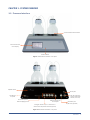
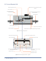
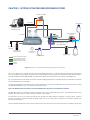
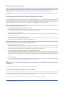
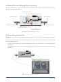
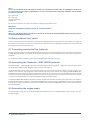
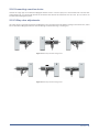
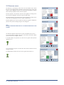
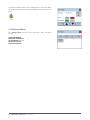
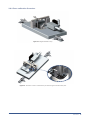
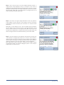
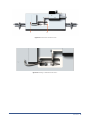
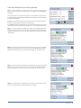
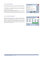
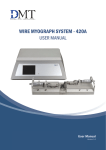
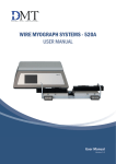
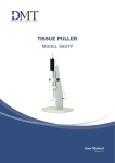
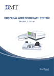
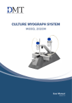
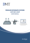
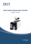
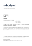
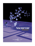
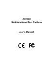
PRESSURE INTERFACE
FOR PRESSURE MYOGRAPH SYSTEMS
User Manual
Version 1.1
1
2
PRESSURE INTERFACE - USER MANUAL
PRESSURE INTERFACE
FOR PRESSURE MYOGRAPH SYSTEMS
TRADEMARKS
PowerLab® and LabChart® are registered trademarks of ADInstruments Pty Ltd.
The names of specific recording units, such as PowerLab 4/35, are trademarks of ADInstruments Pty Ltd.
Danish Myo Technology A/S reserves the right to alter specifications as required.
This document was, as far as possible, accurate at the time of printing.
Changes may have been made to the software and hardware it describes since then.
New information may be supplied separately.
This documentation is provided with the
Pressure Interface
No part of this document may be reproduced by any means without
the prior written permission of Danish Myo Technology A/S.
Copyright © Danish Myo Technology A/S
TRADEMARKS
3
CONTENTS
Trademarks......................................................................................................................................................................................... 3
Safety.................................................................................................................................................................................................. 5
Unpacking the Pressure Interface and Myograph System............................................................................................................. 6
Chapter 1 - System overview............................................................................................................................................................ 7
1.1 Pressure Interface............................................................................................................................................................................ 7
1.2 Pressure Myograph Unit................................................................................................................................................................... 8
Chapter 2 - Setting up the Pressure Myograph System................................................................................................................. 9
2.1 Setting up step-by-step ...................................................................................................................................................................10
2.2 Setting up the complete Pressure Myograph System...................................................................................................................10
2.3 The first weight and pressure calibrations....................................................................................................................................10
2.4 External Pressure Myograph Unit connections ............................................................................................................................11
2.5 Connecting perfusion flow .............................................................................................................................................................11
2.6 Extra perfusion inlet/outlet ...........................................................................................................................................................12
2.7 Connecting superfusion flow (optional) ........................................................................................................................................12
2.8 Connecting the Flowmeter – DMT 161FM (optional) ...................................................................................................................12
2.9 Connecting the oxygen supply .......................................................................................................................................................12
2.10 Connecting a suction device ........................................................................................................................................................13
2.11 3-Way valve adjustments .............................................................................................................................................................13
Chapter 3 - The Pressure Interface menus ................................................................................................................................... 14
3.1 General description of how to navigate the touch-screen............................................................................................................14
3.1 Power-up screen..............................................................................................................................................................................14
3.2 Main Menu.......................................................................................................................................................................................14
3.3 Pressure menu................................................................................................................................................................................16
3.4 Heat Menu....................................................................................................................................................................................... 17
3.5 Timer Alarm Menu........................................................................................................................................................................... 17
3.6 Settings Menu.................................................................................................................................................................................18
3.6.1 Force calibration Procedure.....................................................................................................................................................19
3.6.2 Pressure Calibration Procedure...............................................................................................................................................22
3.6.3 pH Calibration Procedure (optional)........................................................................................................................................25
3.6.4 Analog Record Out Select (optional)........................................................................................................................................26
3.6.5 Interface settings......................................................................................................................................................................27
3.6.5.1 TEMPERATURE DIFFERENCE (OFFSET).........................................................................................................................27
3.6.5.2 pH SETUP MENU.............................................................................................................................................................28
3.6.5.3 FACTORY DIAGNOSTICS..................................................................................................................................................28
Appendix 1 - System Specifications .............................................................................................................................................. 29
4
PRESSURE INTERFACE - USER MANUAL
SAFETY
The Pressure Interface has been designed for use only in teaching and research applications. It is not intended for clinical or critical life-care use and should never be used for these purposes. Nor for the prevention, diagnosis, curing, treatment, or alleviation
of disease, injury, or handicap.
• Do not open the unit: the internal electronics pose a risk of electric shock.
• Do not use this apparatus near water.
• To reduce the risk of fire or electric shock, do not expose this apparatus to rain or moisture. Objects filled with liquids should
not be placed on the apparatus.
• Do not block any ventilation openings. Install in accordance with the manufacturer’s instructions.
• Only use secure industry standard connectors and tubing for pressure connections. Faults, defects and mistakes due to
wrong connections void warranty. We are not accountable for results and mistakes due to inappropriate pressure hookup.
• Do not install near any heat sources such as radiators, heat registers, stoves, or other apparatus that produce heat.
• Only use attachments and accessories specified by the manufacturer.
• Unplug this apparatus during lightning storms or when unused for long periods of time.
The Pressure Interface is delivered with an external 100-240VAC to 24VDC ADAPTER.
Protect the power ADAPTER and cord from being walked on or pinched. Particularly at power plugs and the point where they connect to the apparatus.
Refer all servicing to qualified service personnel. Servicing is required when the apparatus has been damaged in any way; such
as, the power-supply cord or plug is damaged, liquid has spilled onto or objects have fallen into the apparatus, the apparatus has
been exposed to rain or moisture, does not operate normally, or has been dropped.
SAFETY
5
UNPACKING THE PRESSURE INTERFACE AND MYOGRAPH SYSTEM
Please take a few minutes to carefully inspect your new Pressure Myograph System for damage, which may have occurred during
handling and shipping. If you suspect any kind of damage, please contact us immediately and the matter will be pursued as soon
as possible. If the packing material appears damaged, please retain it until a possible claim has been settled.
We recommend that you store the packing material for any possible future transport of the Pressure Myograph System. In case
of transport, and the original packing material is unavailable, please contact the DMT Sales Department for advice and packing
instructions. After unpacking your new Pressure Myograph System, please use the following list to check that the system is
complete:
Pressure Myograph Unit:
• Force calibration kit (including “bridge”, “balance” and 2 gram weight)
• Resistance tube shunt (calibration tube)
• Two glass cannulas
• Chamber cover
Pressure Interface:
• Pressure Interface-to-chamber cable with a temperature probe
• Power adapter (the shape of the AC plug varies by country; be sure that the plug has the right shape for your location)
• USB cables for PC connection.
• Atlas Copco Cablair hose for main pressure supply
• Two 500ml Schott Duran Bottles with specially designed screw caps
Riester “Big Ben” Pressure Manometer
Accessories:
• Allen key
• Spare screws
• Small screwdriver
• Suture wire
• Tube of high-vacuum grease
• Tube of grease for linear slides
• Silicone tubing: internal diameter 1mm
Computer, hardware, software & manuals:
• USB digital camera (optional)
• CD with DMT Pressure Myograph Systems user manuals
• CD with MyoVIEW II software program (optional)
• Computer (optional)
FlowMeter – Model 161FM (optional):
• User manual “FlowMeter – Model DMT 161FM”
• MyoFlow™ FlowMeter software including drivers (CD-ROM)
Peristaltic pump for superfusion flow (optional):
• Watson Marlow peristaltic pump
6
PRESSURE INTERFACE - USER MANUAL
CHAPTER 1 - SYSTEM OVERVIEW
1.1 Pressure Interface
2 x 500 ml Schott Duran bottles
Pressure Interface
touch display
Power indicator
Figure 1.1 The Pressure Interface - front panel
ON/OFF switch
Earth point
Inlet for oxygen/carbogen to pressurize
bottles (max 1 bar)
24V DC port
for power
Connection port for
Pressure Myograph unit
USB connection port
for computer
Analogue recorder output - connection to
external data acquisition software (optional)
Connection port
for pH meter (optional)
Figure 1.2 The Pressure Interface - rear panel
CHAPTER 1
7
1.2 Pressure Myograph Unit
Micropositioner for vertical adjustment of glass
cannulas
Horizontal adjustment screw
Force transducer
Outlet pressure transducer
connection pipe
25 pin serial port for communication with
Pressure Interface
Inlet 3-way valve
Outlet 3-way valve
Outlet pressure transducer P2
Inlet pressure transducer P1
Force transducer pin
Micropositioner for longitudinal adjustment of glass cannulas
Figure 1.3 The Pressure Myograph Unit
Fixation plate for left glass cannula
Fixation plate for right glass cannula
Outlet connecting pipe
Perfusion inlet pipe
Silicone tube connecting outlet connecting
pipe with left glass cannula
Silicone tube connecting perfusion inlet pipe and right
glass cannula
Right glass cannula
Left glass cannula
Myo chamber window
Figure 1.4 The Pressure Myograph chamber - magnified
8
PRESSURE INTERFACE - USER MANUAL
CHAPTER 2 - SETTING UP THE PRESSURE MYOGRAPH SYSTEM
FlowMeter 161FM
USB cable
Waste Bottle
USB cable
Data Acquisition
Software and PC
Peristaltic Pump
(optional)
USB cable
P2
P1
Pressure Interface
Pressure Myograph - 111P
(incl. Microscope)
pH sensor
(optional)
Pressure and
Oxygen Supply
Vaccum Pump
(optional)
Outlet Superfusion buffer
Inlet Superfusion buffer
Inflow Perfusion buffer
Outflow Perfusion buffer
Cables
Tubing
Sucction Bottle
Oxygen Supply
Superfusion
Buffer
Figure 2.1 Example of the Complete Pressure Myograph System - Model 111P
Fig. 2.1 is a diagram of a complete setup for the Pressure Myograph System - 111P. The diagrams include optional equipment
such as a peristaltic pump to enable superfusion flow and pH probes for measuring pH in the superfusion buffer. Also the diagram
includes the DMT Flowmeter DMT 161FM. The Flowmeter enables flow measurements in the range of 15-4000μl/min.
Fig. 2.1 is intended as an overview of the setup of the Pressure Myograph Systems. A detailed step-by-step description is provided
in the remaining sections of Chapter 2.
The Pressure Myograph System will work with a range of different microscopes; the DMT Microscope, Zeiss Axio Vert A1, Nikon
TS-100F, Motic AE2000 or your own inverted microscope of choice.
NOTE: THE MICROSCOPE IS ESSENTIAL FOR THE DIMENSIONAL ANALYSIS OF THE MOUNTED VESSELS.
The DMT Microscope is a standard inverted microscope with a built-in digital CCD USB camera. The DMT Microscope is very
effective and recommended in setups requiring standard image analysis.
The Zeiss Axio vert A1 is an inverted microscope that provides the highest degree of flexibility in image analysis. The Zeiss
Axio vert A1, a Nikon TS-100F and Motic AE 2000 enable the use of a wide range of objectives and facilitate sophisticated
fluorescence techniques.
Contact the DMT Sales Department for further product information and prices on any optional equipment, including microscopes.
CHAPTER 2
9
2.1 Setting up step-by-step
NOTE: IF YOU HAVE PURCHASED A COMPUTER FROM DMT IN CONJUNCTION WITH YOUR PRESSURE MYOGRAPH SYSTEM
THEN THE MYOVIEW II DATA ACQUISITION SOFTWARE HAS ALREADY BEEN INSTALLED WITH DRIVERS FOR THE DIGITAL CCD
USB CAMERA. FOLLOW THE PROCEDURES IN SECTION 2.2 TO SETUP THE PRESSURE MYOGRAPH SYSTEM.
If you have not purchased a computer from DMT follow the MyoVIEW II Quick Installation Guide to install MyoVIEW II on your own
computer.
2.2 Setting up the complete Pressure Myograph System
This section describes how to connect the cables in the Pressure Myograph System as illustrated in figure 2.1. Before connecting
any of the myograph equipment ensure that for the 110P Pressure Myograph system that the USB camera is connected to your
PC. For the 111P Pressure Myograph system please connect both USB cable of the DMT microscope to the computer. Install the
MyoVIEW II Data Acquisition Software on your PC as described in the MyoVIEW II Quick Installation Guide.
NOTE: BEFORE PROCEEDING WITH THE CONNECTION PROCEDURE, MAKE SURE THAT THE PRESSURE INTERFACE, THE
MICROSCOPE AND THE PC ARE SWITCHED OFF.
1. Pressure Myograph Unit to Pressure Interface connection:
Connect the Pressure Myograph Unit to the Pressure Interface by using the grey 25/44-pin connection cable. The end of the
cable with the temperature probe is connected to the Pressure Myograph Unit.
2. Pressure Interface to PC connection:
Connect the Pressure Interface to the computer with the USB cable, from the back panel of the Pressure Interface to the
USB port on the computer.
3. Pressure Interface and oxygen supply connection:
Connect the “Oxygen” inlet on the back panel of the Pressure Interface to an adjustable oxygen supply using the “Atlas
Copco Cablair hose” delivered with the Pressure Myograph System.
IMPORTANT MAKE SURE THAT THE HOSE IS SECURELY FASTENED TO THE “OXYGEN” INLET USING THE HOSE CLIP. THE
PRESSURE FROM THE OXYGEN SUPPLY MUST NOT EXCEED 1.0 BAR!
4. Microscope/camera to PC connection:
Inside the DMT Microscope there is a USB camera wired to a USB cable and one USB cable to power the microscope light.
Connect the two USB cable from the DMT microscope to the computer USB ports. For the 110P system with the external
USB-camera connect the USB cable from the USB Camera to your PC for the 110P system.
5. Pressure Interface to external data acquisition system connection (optional):
If you have not obtained the MyoVIEW II software the four BNC ports on the rear of the Pressure Interface enable connection
of an external data acquisition system for recording inlet pressure P1, outlet pressure P2, longitudinal force, probe
temperature, chamber temperature, flow ON/OFF, pressure ON/OFF, pH1 value and (Optional Dig out1, Dig out2, Dig in1 dig
in2).
6. Turn on the power:
Turn the main power to the Pressure Interface ON at the power switch. Turn ON the computer. The Pressure Myograph
System is now ready to be used with MyoVIEW II Data Acquisition Software.
NOTE:
A DETAILED GUIDE TO CONNECTING THE PRESSURE MYOGRAPH SYSTEM FOR AN EXPERIMENT IS DESCRIBED IN DETAIL
IN CHAPTER 5.
For installation of MyoVIEW II refer to the MyoVIEW II Quick Installation Guide.
2.3 The first weight and pressure calibrations
Prior to shipment the Pressure Myograph System has gone through two days of continuous testing, including final weight and
pressure calibrations. However in order to ensure that the Myograph is working at highest performance, DMT recommends that
new weight and pressure calibrations are performed before the first use.
The weight and pressure calibration procedures are described in detail in chapter 3.6.1 and 3.6.2.
10
PRESSURE INTERFACE - USER MANUAL
2.4 External Pressure Myograph Unit connections
This section illustrate how to connect the perfusion circuit, the superfusion circuit, oxygen supply, pressure supply and suction
device on to the Pressure Myograph unit.
Suction pipe to vacuum
Superfusion outlet
Perfusion outlet P2
Perfusion inlet P1
Extra perfusion outlet
Extra perfusion inlet
Superfusion inlet
Pipe for oxygen supply
Access hole for reagents, buffer,
temperature or pH probe
Figure 2.2 External Pressure Myograph connection
2.5 Connecting perfusion flow
The perfusion flow is controlled by the Pressure Interface. Instructions on how to control the perfusion flow are provided in
chapter 3.
To connect the Pressure Interface to the Pressure Myograph unit, use the silicone tube (internal diameter 1mm) delivered with
the Pressure Myograph System.
• Connect the “perfusion inlet” at P1 on the Pressure Myograph (see figure 2.3) to the P1 outlet on the cap of the buffer bottle
(see fig. 2.3).
• Connect the “perfusion outlet” at P2 on the Pressure Myograph Unit (see figure 2.3) to the P2 inlet on the Pressure Interface
(see fig. 2.3).
P2
P1
P1
P2
Figure 2.3 Pressure Interface tube connection
CHAPTER 2 11
NOTE I
TO FILL THE TUBING AND AVOID AIR BUBBLES, MOUNT THE “CALIBRATION SHUNT TUBE” AS DESCRIBED IN CHAPTER 5.
FILL THE P1 SCHOTT BOTTLE WITH A MAXIMUM OF 400 ML OF BUFFER. IN THE “PRESSURE” MENU SET THE PRESSURE
P1 AND P2 AS FOLLOW:
P1 = 150mm Hg
P2 = 70mm Hg
Set the Pressure ON
Set Flow ON
Let the pressure regulator run until no air bubbles are visible in the perfusion circuit.
IMPORTANT
NEVER RUN AIR BUBBLES THROUGH A VESSEL AS THIS MAY DAMAGE IT.
NOTE II
NEVER FILL THE BUFFER BOTTLE WITH MORE THAN 400 ML OF BUFFER AS HIGHER VOLUMES MAKES PRECISE CONTROL
OF THE PRESSURE MORE DIFFICULT.
2.6 Extra perfusion inlet/outlet
The extra perfusion inlet/outlet 3-way valves on the Pressure Myograph allow the introduction of special agents or reagents to
the perfusion circuit during an experiment. They are situated at P1 and P2 on the Myograph Chamber and the small handle on
top of the valves controls the flow direction.
2.7 Connecting superfusion flow (optional)
Creating a superfusion flow in the Pressure Myograph Chamber requires an external peristaltic pump, which is not part of the basic
Pressure Myograph System. Contact DMT for further information about recommended perfusion pump models, specifications
and prices.
The superfusion circuit is connected to the Pressure Myograph Unit as illustrated in fig. 2.1.
2.8 Connecting the Flowmeter – DMT 161FM (optional)
The DMT Flowmeter – Model 161FM is optional for flow measurements in the range of 15 – 4000μl/min. The Flowmeter is easily
combined with any DMT Pressure Myograph System as illustrated in fig. 2.1.
Use of the Flowmeter permits control of intravascular pressure, pressure gradient and flow conditions with high accuracy. This
enables in vitro studies on vessel segments under conditions very close to those found in vivo. Adding the DMT FlowMeter DMT
161FM to the Pressure System also enables measurement of flow rate as a parameter. The Flowmeter data will make it possible
to record live traces of the flow dependent parameters as shear stress, Reynolds number and vascular resistance due to changes
in vessel structure and function in various physiological and pharmacological studies.
To add the FlowMeter DMT161FM to the Pressure System the cable from the flow is attached to the “Flowmeter” port marked on
the backside of the Pressure Interface. The Software MyoVIEW II will recognize the Flowmeter DMT161 as soon as it is connected
to the Pressure Interface and will be ready for use immediately. Please consult the MyoVIEW II video manuals linked in the help
menu of MyoVIEW II.
2.9 Connecting the oxygen supply
Connect the oxygen supply pipe on the Pressure Myograph Chamber cover to an adjustable oxygen supply. See figure 2.2 “Pipe
for oxygen supply”.
12
PRESSURE INTERFACE - USER MANUAL
2.10 Connecting a suction device
Connect the “large” pipe on the Pressure Myograph Chamber cover to a vacuum pump via a suction bottle and a vacuum valve
as illustrated in fig. 2.1. The internal diameter of the silicone tube used for this connection must be 2 mm. (A 2 mm tube is not
included with the Myograph System).
2.11 3-Way valve adjustments
The 3-way valves on each side of the Pressure Myograph Unit (at P1 & P2) have three different settings to control the inlet / outlet
flow to the Pressure Myograph Chamber. The flow settings are illustrated in fig. 2.4 and fig. 2.5.
Figure 2.4 Three-way valve flow settings at P1
Figure 2.5 Three-way valve flow settings at P2
CHAPTER 2 13
CHAPTER 3 - THE PRESSURE INTERFACE MENUS
This chapter contains a detailed description of how to navigate the touch-screen menus and how to use the special features of
the Pressure Interface.
3.1 General description of how to navigate the touch-screen
Menus on the Pressure Interface are all accessible by a touch-screen. To access a menu, simply touch the corresponding button
on the screen. When a setting needs to be changed, press the relevant “SELECT” button or in the display below, touching the
“ON” or “OFF” buttons.
The line selected will turn blue, indicating that the interface is in edit mode
and waiting for input. When “DEFAULT” is chosen, a default value will be
displayed. To change the numeric value for the selected parameter touch
the up or down arrow keys.
Once the desired setting has been chosen, pressing “ENTER” will save the
selection, and the new value will be stored in memory. The selected line will
revert to black. Pressing the white “X” in the red box will exit the menu and
return you to the Main Menu.
3.1 Power-up screen
After turning on the Pressure Interface, an “Introduction” screen appears.
It displays the software versions number. While this screen is displayed the
system is auto-initialising.
After a few seconds, the “MAIN MENU” display will appear.
3.2 Main Menu
The Main Menu gives a good overall picture of how the Pressure Interface is working. It displays values for the input pressure,
output pressure, force, pH, probe temperature and time, and the status of systems including the time, heat, flow and pressure.
14
PRESSURE INTERFACE - USER MANUAL
Icon for Pressure ON/OFF
Icon for Flow ON/OFF
Icon for Heater ON/OFF
Timer
Icon for Buzzer ON/OFF
* If ON the icon is GREEN
ZERO key
This key is used to zero the
force output
Pressure setup menu
Heat setup menu
Timer/alarm setup menu
Settings menu
Buzzer icon:
This icon indicates the status on the Buzzer.
If the icon is grey the Buzzer is OFF.
If the icon is green the Buzzer is ON (active).
The Buzzer will make a sound when the Timer reaches zero.
OFF
Timer:
The Timer is a countdown watch that can be set to a maximum of 24 hours.
If the buzzer is activated it will sounds when the timer reached zero.
Heat icon:
This icon indicates the status of the chamber heat.
If the icon is grey Heat is OFF.
If the icon is green the Heat is ON (active).
Flow valve icon:
This icon indicate the status on the Flow valve.
If the icon is grey the Flow valve is OFF (NO Flow).
If the icon is green the Flow valve is ON (active).
Pressure icon:
This icon indicates the status of the Pressure regulation.
If the icon is grey the Pressure regulation is OFF.
If the icon is green the Pressure regulation is ON (active).
ON
00:00:00
OFF
ON
OFF
ON
OFF
ON
Zero key:
This key is used to zero the output from the force transducer. Pressing
this key will reset the baseline of the chart traces without affecting the
calibrations.
CHAPTER 3 15
3.3 Pressure menu
The Pressure is controlled from this menu. Use the “SELECT” key to select
the line to be changed. When selected the line change color is blue (edit
mode). Use the “DEFAULT” button or the arrow keys to change the setpoint
value. Pressing “ENTER” will save the new setpoint.
P1 Inlet setpoint is the pressure value that the regulator is setting on the
inlet side of the Myograph. Pressure range is 0-250mmHg.
P2 Outlet setpoint is the pressure value that the regulator is setting on the
outlet side of the Myograph. Pressure range is 0-250mmHg.
Pressure gradient This sets the speed at which the regulator modifies the
pressure. The pressure change range is 1-10mmHg/sec.
NOTE
P1 MUST NEVER BE LOWER THAN P2 TO PREVENT BACKFLOW IN THE
SYSTEM.
The Pressure regulator and the Flow are also controlled from this menu.
To turn the Pressure regulator ON press the Pressure ON button. When
activated the button changes to Green.
In the Main Menu the pressure icon also turns to green when pressure
regulation is on.
ON
To turn the Flow ON press the Flow ON button. When activated the key
changes to Green.
In the Main Menu the Flow icon also turns to green when Flow is on.
ON
16
PRESSURE INTERFACE - USER MANUAL
3.4 Heat Menu
The Chamber and Bottle heating temperature are controlled from this menu.
To turn the heat on, or to change the temperature for the system, press the
“HEAT” button in the Main Menu. The display will enter the Heat menu and
allow the user to change the system temperature, as well as turn heat on or
off. Pressing “DEFAULT” will automatically reset the temperature setpoint to
37°C. Manually change the temperature by pressing the up or down arrows.
Pressing “ENTER” will save the new temperature setpoint.
To turn the heat on, touch “ON” and the “ON” button will turn green. The
system will heat to the designated temperature setpoint.
In the Main Menu the thermometer icon turns to green when the heat is on.
ON
3.5 Timer Alarm Menu
The Timer and Buzzer Alarm are controlled from this menu.
Use ”SELECT” to program the timer. The timer can be programmed in
intervals from 0 to 23:59:59 (Hours : minutes : seconds). When Set Timer
is selected use the up and down arrows to program the timer. The hours are
programmed first, and then use the “RIGHT” button to get to the minutes
and then the seconds.
Pressing “ENTER” will save the programmed time.
To start the “Timer” press the Timer “ON” button. When the Timer is on, the
button turns green. When the timer reached zero it switches automatically
to “OFF”.
If the Buzzer is set ON it will make a tone when the timer reaches zero.
CHAPTER 3 17
To activate the “Buzzer Alarm” press the Buzzer Alarm “ON” button. When
ON the button turns green and in the Main Menu the bell icon also turns
green.
ON
3.6 Settings Menu
The “Settings Menu” contains several sub-menus. These sub-menus
include:
FORCE CALIBRATION
PRESSURE CALIBRATION
pH CALIBRATION (optional)
RECORD OUT SELECT
INTERFACE SETTINGS
18
PRESSURE INTERFACE - USER MANUAL
3.6.1 Force calibration Procedure
Figure 3.1 - Weight Calibration Set up
Figure 3.2 - Illustration of how to fit the balance just behind the glass cannula fixation plate
CHAPTER 3 19
Enter the FORCE CALIBRATION sub-menu to begin the transducer
calibration. The display will show the force calibration procedure.
Step 1 - The calibration procedure is listed in 6 individual steps and needs
to be performed one at a time to calibrate the system. Step 1 involves
setting up the chamber for calibration. Fill the chamber to a normal level
with double-distilled water. Press “NEXT STEP”.
Step 2 - Involves setting up the calibration kit for the actual weight
calibration.
Make sure that the tip of the calibration bridge arm is placed behind the
glass cannula fixation plate as illustrated in fig. 3.71. Carefully move the
calibration bridge until the tip of the arm is placed freely behind the glass
cannula fixation plate. It should not be touching the fixation plate.
Press “NEXT STEP” when the calibration kit has been properly placed.
Step 3 - This step initiates the heating process for the chambers. In order for
the calibration to be accurate, the transducers must be heated to the same
temperature to be used in your experiment. This allows for heat-induced
expansion of the electronic parts in the transducer. Otherwise, inaccurate
readings and transducer drift may occur.
To start heating, press “HEAT ON”.
Covering the chambers with the chamber covers will expedite the heating.
Place the temperature probe into the chamber for the first calibration to
monitor when the chamber has reached the target temperature. With the
covers heating will take about 20 to 30 minutes for the chambers and
transducers to reach 37°C. Once the chamber(s) are heated and have
reached the target temperature, press “NEXT STEP”.
20
PRESSURE INTERFACE - USER MANUAL
Step 4 - This is the first step in the actual weight calibration process. A
4-digit number will be displayed in blue at the bottom of the screen. If
nothing has been disturbed during the heating process, the zero / 0 gram
calibration should be stable. The 4-digit number will not fluctuate and after
30-45 seconds “NEXT STEP” can be pressed. If the 4-digit number is not
stable, wait before pressing “NEXT STEP”.
Step 5 - This step is the 2 gram weight calibration. At this step, place the
2 gram weight in the pan closest to the transducer (over the transducer)
to simulate the stretch created by the contraction of a mounted muscle
preparation.
Remember, a 2 gram weight in a 90° vector is divided, and the transducer
will only detect 1 gram or 9.81 mN of force. The weight placement should
cause a positive increase in the 4-digit number. Wait at least 30 to 45
seconds for the applied force to stabilize before pressing “NEXT STEP”. Only
when the 4-digit number has stabilized should you press “NEXT STEP”.
Step 6 - This step verifies that the calibration was performed correctly. The
“Force Chamber” reading should be 9.81 ± 0.1 mN. If the “Force Chamber”
reading is off by more than 0.1 mN, then remove the weight, press “BACK” to
return to Step 4, and repeat the calibration process. If the “Force Chamber”
reading is satisfactory, then press “NEXT STEP” to end the calibration.
After calibrating the force transducer, carefully remove weight, balance
and calibration bridge. The Pressure Myograph System is now ready for
longitudinal force measurements.
CHAPTER 3 21
3.6.2 Pressure Calibration Procedure
The setup to perform the pressure transducer calibration procedure is illustrated in Fig. 3.3. Carefully follow the procedure
described below to calibrate the Pressure Interface System. The calibration procedure is listed in 5 individual steps and needs to
be performed one at a time to calibrate the system.
Figure 3.3 Illustration of setup for pressure transducer calibration
Step 1 - involves setting up the Myograph Chamber for pressure calibration.
Step 2 - Connect the “Big Ben” Pressure Manometer to the 3-way valve at P1 on the Pressure Myograph Chamber as illustrated
in fig. 3.3.
Step 3 - Inside the Myograph Chamber, on the right hand side, is a small stainless steel pipe, which is connected to the right glass
cannula via a small silicone tube (Fig. 3.4 B). Carefully disconnect the silicone tube from the stainless steel pipe.
Step 4 - Carefully disconnect the silicone tube between the “outlet connecting pipe” and the “outlet pressure transducer
connecting pipe”, fig. 3.4 A.
Step 5 - Close the inlet from the Pressure Interface to P1 by turning the handle on the 3-way valve towards the normal inlet way.
The inlet to P1 now comes from the pressure manometer. See fig. 3.3.
22
PRESSURE INTERFACE - USER MANUAL
A
B
Figure 3.4 Disconnection of silicone tubes
Figure 3.5 Mounting of “Resistance tube shunt”
CHAPTER 3 23
3.6.2.1 Pressure calibration
Press “setting” in the “Main Menu” and then press “Pressure Calibration”
Step 1 - Press “NEXT STEP” when the system is ready.
Step 2 - Apply a pressure of 50mm Hg on the Pressure Myograph using the
“Big Ben” Pressure Manometer. When the 3 blue lines of relative values
stabilize, go to “NEXT STEP”.
The relative values should between 3300 to 3900.
Step 3 - Apply a pressure of 125mm Hg to the Pressure Myograph Chamber
using the “Big Ben” Pressure Manometer. When the 3 blue lines of relative
values stabilize, go to “NEXT STEP”.
The relative values should between 3900 to 4500.
Step 4 - Apply a pressure of 200mm Hg to the Pressure Myograph Chamber
using the “Big Ben” Pressure Manometer. When the 3 blue lines of relative
values stabilize, go to “NEXT STEP”.
The relative values should between 4600 to 5200.
Step 5 - The calibration is now finished. The readings in the three bottom
lines are the actual pressure on all three pressure sensors. The values must
be 200.0 +/-1.0mm Hg.
Carefully remove the “Calibration Shunt Tube” and reconnect the tubing to
the glass cannulas.
24
PRESSURE INTERFACE - USER MANUAL
3.6.3 pH Calibration Procedure (optional)
Before the pH calibration is performed be sure to select the way the pH
sensor is to be used. See the sub-menu “pH SETUP” under INTERFACE
SETTINGS.
The temperature is an important parameter in the calibration formula and
is obtained automatically if AUTO is selected in Temperature compensation
function, shown below.
If MANUAL is selected, the Manual temperature is used in the pH calibration
formula, and the temperature probe is de-activated.
In the MANUAL mode, the temperature of the calibration buffers is measured
with a thermometer and entered manually in the “manual temperature” line.
Step 1 - The pH calibration procedure is listed in 4 individual steps and
needs to be performed one at a time. Step 1 involves cleaning the pH probe
and the temperature sensor with double distilled water. When ready Press
“NEXT STEP”.
Step 2 - Place the pH-meter electrode and temperature probe in the HIGH
buffer solution (here pH 7) and turn on stirring of the HIGH buffer solution.
When the relative pH output in the blue line is stable, go to “NEXT STEP”.
Step 3 - Place the pH-meter electrode and temperature probe in the LOW
buffer solution (here pH 4) and turn on stirring of the LOW buffer solution.
When the relative pH output in the blue line is stable, go to “NEXT STEP”.
Step 4 - The calibration is now finished. The values in the two bottom lines
are the actual pH reading, and the temperature reading.
CHAPTER 3 25
3.6.4 Analog Record Out Select (optional)
The RECORD OUT SELECT sub-menu determines how data is sent to the
BNC analog outputs at the back of the Pressure Interface. There are 4
analog outputs. Each output is individually programmable. Any change
made to RECORD OUT will only affect the data collected by the external data
acquisition system (such as an AD Instruments PowerLab). So it is important
to check the data acquisition setup when a change is made to the analog
output with this setting. The analog output works in range of -2,5V to +2,5V.
Use “SELECT” to select the OUT channel number to be changed. Press
“ENTER” to go to the output setup.
Use “SELECT” to select the line to be changed.
Use the arrow keys or “DEFAULT” to change/select a new setup.
26
PRESSURE INTERFACE - USER MANUAL
The following parameter in the Pressure Interface can be selected as output
on the Analog channel. Force, Probe temperature, Chamber temperature,
pH1, Pressure regulation ON/OFF, Flow ON/OFF, (Optional: Digital output 1,
Digital output 2, Digital input 1, Digital input 2), Pressure P1, Pressure P2.
When the parameter is selected press “ENTER” to save the value.
The output range is -2,5V to +2,5V. The user can select the parameter value
that gives
-2,5V and the value that gives +2,5V. In this example -100mN is -2,5V and
+100mN is +2,5V.
Selecting asymmetrical values is also valid. They can be -2,5V = 0mN and
+2,5V = 100mN.
NOTE
REMEMBER TO PRESS THE “ENTER” KEY TO SAVE THE LINE CHANGES
TO MEMORY.
3.6.5 Interface settings
The INTERFACE SETTINGS sub-menu in SETTINGS has an additional 3 submenus. These 3 additional sub-menus are:
TEMPERATURE DIFFERENCE
pH SETUP
FACTORY DIAGNOSTICS
3.6.5.1 TEMPERATURE DIFFERENCE (OFFSET)
The TEMPERATURE DIFFERENCE function allows the user to fine-tune the
temperature setpoint of the system. Although the temperature setpoint for
the system can be set in the HEAT MENU, the actual temperature for the
system may not heat to the exact setpoint. This function allows the user to
adjust the temperature of the chamber and bottle individually so the EXACT
temperatures can be reached. This is referred to as a temperature offset
(TEMP OFFSET on chamber). The “SELECT” and “ALL” functions are the
same in this menu as previously described. Pressing “ENTER” will save the
values for future experiments.
CHAPTER 3 27
3.6.5.2 pH SETUP MENU
Before the pH calibration is performed, be sure to have selected the way the
pH sensor is intended to be used. This is done in the sub menu “pH SETUP”.
The temperature is an important parameter in the calibration formula
and is obtained automatically if AUTO is selected in the Temperature
compensation, as shown below.
If MANUAL is chosen, the Manual temperature is used in the pH calibration
formula, and the probe temperature is deactivated.
In the MANUAL mode, the temperature of the calibration buffers is measured
with a thermometer and entered manually in the “manual temperature” line.
3.6.5.3 FACTORY DIAGNOSTICS
Entering FACTORY DIAGNOSTICS will display the LOGIN CODE TO
DIAGNOSTICS window. This window is for trained technicians and is used for
diagnostics and troubleshooting purposes. The general user will not have
access to this window. Entering the proper 5-digit pin number, however, will
give the trained technician access to Diagnostics panels that will provide
information during a malfunction, or mechanisms to change other settings
controlled by the onboard computer.
28
PRESSURE INTERFACE - USER MANUAL
APPENDIX 1 - SYSTEM SPECIFICATIONS
TECHNICAL SPECIFICATIONS
External 100-240VAC to 24VDC adapter: ±10%
Current max.: 3.3Amps at 24VDC.
Dimensions LxDxH in cm: 34 x 25 x 15
Net weight: 5kg.
Environmental humidity: 20% to 80% RH, non-condensing.
Environmental operating temperature: +15 to +40°C.
Environmental storage temperature: +4 to +70°C.
Fluid capacity: 500 ml bottles. We recommend a volume of 400ml to ensure optimal pressure regulation.
One pH input range:
pH 0-14
pH calibration: manual with instructions on the display.
4 analog outputs: BNC connectors at rear to connect to external data recorder.
Analog output range: ±2.5Volt.
Output impedance: <200 Ohm.
Air connection: maximum pressure 1 Bar.
USB connector: For downloading firmware and connection to PC.
TRANSDUCER DATA
Maximum range: ±200mN.
Operating temperature: +15 to +50°C.
Frequency range: 0 – 20Hz.
APPENDIX 1 29
Aalborg Hospital South • Academic Medical Center Amsterdam • Academy of Sciences of the Czech Republic • Actelion Pharmaceuticals Ltd • Ahmadu Bello University • Akzo Nobel/Organon • Albert
Einstein College of Medicine • Albert-Ludwigs-Universität Freiburg • Arete Therapeutics • Aarhus Kommunehospital • Arizona State University • Asterand UK Ltd. • Aston University • AstraZeneca •
AstraZeneca R&D Mölndal • Aventis Pharma • Bayer HealthCare AG • Baylor College of Medicine • Bristol-Myers Squibb • Brock University • Bulgarian Academy of Sciences • Campus Charité Mitte •
Cardiff University • Case Western Reserve University • Charles University • Childrens Hospital of Pittsburgh • Chinese University of Hong Kong • Christian-Albrechts-Universität zu Kiel • Clinica Medica,
PUGD Udine • CNRS d’Orléans • CNRS UMR 6097 • Columbia University • Copenhagen Hospital Glostrup • Copenhagen University • Cork University Maternity Hospital • Cornell University • Coventry
University • CV Therapeutics Inc. • Cytokinetics Inc. • Daegu Catholic University • Deakin University • Der Universität Freiburg • Der Universität Im Neuenheimer Feld 326 • Deutsche Forschungsgemeinschaf
(DFG), Bonn • Duke University • Duke University Pharmacology • Dundalk Institute of Technology • East Carolina University • Eastern Virginia Medical School • Ecole Polytechnique Fédérale De Lausanne
• Ege University • Emory University • Emory University, School of Medicine • Erasmus Universiteit Rotterdam • Federal University of Minas Gerais • Ferring Research Institute Inc. • Florida Atlantic
University • Florida International University • Forschungsverbund Berlin E.V. • Fourth Military Medical University • Franz-Volhard-Clinic • Free University Berlin • Freie Universität Berlin • Friedrich Schiller
University • Fudan University • Georgetown University • Glasgow Caledonian University • Glasgow University • GlaxoSmithKline • Glenfield Hospital • Göteborg University • Grand Vally State University
• Harefield Hospital • Harvard Medical School • Harvard University • Hebei Medical University • Henry Ford Health System • Hospital Clinic (Barcelona) • Hospital Lariboisiere • Hospital Ramón y Cajal
(Madrid) • Hospital Universitario de Getafe (Madrid) • Hospital Universitario La Fe (Valencia) • Hospital Universitario Virgen del Rocío (Sevilla) • Humboldt Universität zu Berlin • ICBM University of Chile
• Imperial College London • Indiana University • INSERM U541 • INSERM U637 • INSERM U644 • INSERM U772 College de France • Inserm U858 • Institut de Pharmacologie Moléculaire et Cellulai
• Institut De Recherches Cliniques De Montréal • Institute of Cellular Biology and • Institute of Immunology & Physiology • Istanbul University • J.W. Goethe-Universität • Jagiellonian University • James
Cook University • Johann-Wolfgang-Goethe-Universität • Johns Hopkins University • Juntendo University • Justus-Liebig-Universität Giessen • Kaohsiung Medical University • Karolinska Institute • KAS
Glostrup • Katholieke Universiteit Leuven • King’s College London • King’s College London GKT School of Medicine • KK Women’s and Children’s Hospital • Klinikum Der Universität Zu Köln •
København Universitet • Korea University • Laboratorios Almirall (Barcelona) • Linköping University • Liverpool University • Loma Linda University • Loyola University At Chicago • Ludwig Maximilians
University • Lund Universitet • Lundbeck Pharmaceuticals • Luther College • M.V.Lomonosov Moscow State University • Manchester Royal Infirmary • Manchester University • Manitoba Institute of Child
Health • Marquette University • Martin-Luther Universität Halle-Wittenberg • Massachusetts General Hospital • Max-Delbrück-Centrum • Mayo Clinic • McMaster University • MDC Berlin • Medical
College of Georgia • Medical College of Wisconsin • Medical University of South Carolina • Memorial University Of Newfoundland • Michigan State University • Mogiglass Artigos Para Laboratorio LTDA
• Monash University • Mount Sinai School of Medicine • Nanyang Technological University • Nat. Inst. Of Pharnaceutical Education & Research • National Defencse Medical Center • National Institute
on Aging • National University of Ireland • NeuroSearch A/S • Neurox Pharmaceuticals LLC • New York Medical College • New York Presbytarian • North Carolina Central University • North Sichuan
Medical College • Norwegian Univ Sci Tech • Novo Nordisk A/S • Ohio State University • Ono Phamaceutical Co., Ltd. • Oregon Health And Science University • Orthologic Corp. • Pathology “Nicolae
Simionescu” • PDL BioPharma • Pennsylvania State University • Pfizer Ltd. • Philipps Universität • Proteon Therapeutics • Queen Mary University London • Queen’s University • Queens University
Belfast • Radboud University Nijmegen Medical Centre • Ranbaxy • RMIT University • Robert Gordon University • Royal College Of Surgeons In Ireland • Ruhr-Universität Bochum • Saarland University
• Saint Louis University • Samsung Deutschland GmbH • Sanofi-Aventis • Shanghai Institute of Materia Medica • Skejby Sygehus, Aarhus • Slovak Academy of Sciences • SmithKline Beecham • South
Florida VA Hospital • St. George’s Hospital • St. Paul’s Hospital • St. Thomas’ Hospital, London • State University of New York • Stony Brook University • Sultan Oaboos University • Swedish Defence
Research Agency, FOI • Swiss Cardiovascular Ct. Bern • Swiss Federal Institute Of Technology • Syddansk Universitet • Technischen Universität Dresden • Technischen Universität München • Temple
University School of Medicine • Texas A&M University HSC • Texas Southern University • The American Cardiovascular Research Institute • The Australian National University • The Chinese University of
Hong Kong • The Cleveland Clinic • The College Of William & Mary • The Edith Wollfson Medical Center • The John Curtin School of Medical Research • The Ohio State University School of Public Health
• The Panum Institute, Copenhagen • The University of Alabama At Birmingham • The University of Chicago • The University of Edinburgh • The University of Hong Kong • The University of Liverpool •
The University of Naples -Federico II • The University of Newcastle • The University of Queensland • The University of Sydney • The University of Texas Medical Branch • Theravance, Inc. • Tokyo Medical
and Dental University, School of Medicine • Tufts University • UCL Université Catholique • UHI Millennium Institute • Ulleval University Hospital • Universidad Autónoma de Barcelona • Universidad
Autónoma de Madrid • Universidad Complutense de Madrid • Universidad de Castilla-La Mancha (Albacete) • Universidad De Chile • Universidad De Murcia • Universidad de Salamanca • Universidad
de Santiago de Compostela • Universidad de Sevilla • Universidad de Valencia • Universidade Do Estado Do Rio De Janeiro • Universit Milano Bicocca • Universitá Degli Studi De Torino • Universitá
Degli Studi Di Brescia • Universitaet Göttingen • Universitaet Hamburg • Universität Bern • Universität Geissen • Universität Göttingen • Universität Hamburg • Universität Heidelberg • Universität
Klinikum Der JWG • Universität Marburg • Universität Regensburg • Universität Rostock • Universität Tübingen • Üniversität Zürich • Universitätshospital Zürich • Universitätsklinik Essen •
Universitätskliniken des Saarlandes • Universitätsklinikum Berlin • Universitätsklinikum Bonn • Universitätsklinikum Carl Gustav Carus • Universitätsklinikum Eppendorf, Hamburg • Universitätsklinikum
Essen • Universitätsklinikum Münster • Universitätsklinikum Schleswig-Holstein • Universitätsmedizin Berlin-Charité • Universite Bordeaux 2 • Université catholique de Louvain • Université D’Angers •
Université de Genéve • Université de Tours • Université Henri Poincaré • Université Victor Segalen • Universiteit Antwerpen • Universiteit GENT • Universiteit Maastricht • Universitetssjukhuset UMAS
MALMÖ • Universitetssykehuset Nord-Norge • Universiti Brunei Darussalam • University College Dublin • University College London • University Hospital (CHUV) • University Hospital of Copenhagen Rigshospitalet • University Hospital Zürich • University Newcastle upon Tyne • University of Aarhus • University of Alberta • University of Amsterdam AMC • University of Arizona • University of Bath •
University of Bern • University ff Birmingham • University of Bonn • University of Brescia • University of Brighton • University of Bristol • University of British Colombia • University of Calgary • University
of California - Irvine • University of Cambridge • University of Catania • University of Cologne • University of Colorado • University of Debrecen Inst Cardio • University of Dresden • University of Dundee
• University of Edinburgh • University of Essen • University ff Exeter • University of Florida • University of Georgia • University of Glasgow • University of Göttingen • University of Groningen • University
of Guelph • University of Heidelberg • University of Iceland • University of IL Urbana-Champ • University of Iowa • University of Kansas • University of Kentucky • University of Leeds • University of
Leicester • University of Liverpool • University of London • University of Louisville • University of Lübeck • University of Lund • University of Maastricht • University of Malaya • University of Manchester
• University of Manitoba • University of Maryland • University of Medicine and Pharmacy • University of Melbourne • University of Miami • University of Michigan • University of Missouri •
University of Montreal • University of Nevada, Reno • University of New Hampshire • University of New Mexico • University of New South Wales • University of North Dakota • University of
North Texas • University of Northern British Columbia • University of Nottingham • University of Osijek • University of Otago • University of Ottawa • University of Oxford • University of
Padova • University of Pennsylvania • University of Pisa • University of Pittsburgh • University of Queensland • University of Rochester • University of Sao Paulo • University of
Saskatchewan • University of Scranton • University of Sheffield Medical School • University of South Alabama • University of Southampton • University of St. Andrews •
University of Strathclyde • University of Sunderland • University of Sydney • University of Szeged • University of Tampere • University of Texas • University of Texas
Health Science Center • University of Toronto • University of Tsukuba, Graduate School of Comprehensive Human Sciences • University of Tübingen •
University of Turku • University of Utah • University of Vermont • University of Virginia • University of Wales • University of Warwick • University of
Washington • University of Zurich • University of Virginia • University Victor Segalen • Virginia Commonwealth University • Wake Forest
University School of Medicine • Washington University in St. Louis • Wayne State University • Wenzhou Medical College
• West Virginia University • Western Michigan University • Westfälische WilhelmsMünster
•
William
DMT A/S
Skejby Science Center
Skejbyparken 152
DK-8200 Aarhus N
Denmark
DMT-Asia Ltd.
Rm 2402B, Great Eagle Centre
23 Harbour Road
Wanchai, Hong Kong S.A.R.
P.R. China
DMT-Asia (China office)
Rm 28C, No. 8 Dong Fang Road
Lu Jia Zui Financial District
Shanghai 200120
P.R. China
DMT-USA, Inc.
201 East Liberty Street
Suite 6
Ann Arbor, MI 48104
USA
Tel.: +45 87 41 11 00
Fax: +45 87 41 11 01
Tel.: +852 6621 8337
Fax: +852 3020 7554
Tel.: +86 (0) 21 5425 1330
Fax: +86 (0) 21 5877 0063
Tel.: +1 770 612 8014
Fax: +1 678 302 7013
www.dmt.dk
[email protected]
[email protected]
www.dmt-asia.com
[email protected]
[email protected]
www.dmt-asia.com
[email protected]
[email protected]
www.dmt-usa.com
[email protected]
[email protected]
30
PRESSURE INTERFACE - USER MANUAL
PRESSURE INTERFACE/04/2013
Universität