1
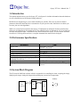
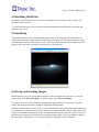
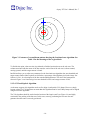
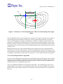
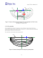
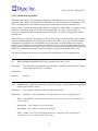
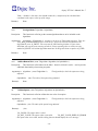
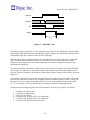
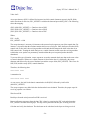
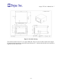
Osprey XT User’s Manual
Revision 7
Contents
1.0 INTRODUCTION........................................................................................................4
2.0 PERFORMANCE SPECIFICATIONS........................................................................4
3.0 SYSTEM BLOCK DIAGRAM.....................................................................................4
4.0 INSTALLING INTELLIAIM.........................................................................................5
5.0 INTELLIAIM...............................................................................................................5
6.0 SAVING AND LOADING IMAGES............................................................................5
7.0 DISPLAY RESOLUTION...........................................................................................6
8.0 SECURITY.................................................................................................................6
9.0 SETUP....................................................................................................................... 6
9.1 Lamp Styles.............................................................................................................................6
9.1.1 Name..................................................................................................................................7
9.1.2 Aim Algorithm...................................................................................................................7
9.1.2.1 HV...............................................................................................................................7
9.1.2.2 Aim Point....................................................................................................................7
9.1.2.3 Aim Sign Convention..................................................................................................7
9.1.2.4 Standard Aim Algorithms...........................................................................................7
9.1.2.4.1 Hot Zone Algorithm.............................................................................................7
9.1.2.4.2 Fractional Zone Algorithm...................................................................................9
9.1.2.4.3 Visual/Optical Algorithm...................................................................................10
9.1.2.4.4 Visual/Optical Plus™ Algorithm.......................................................................11
9.1.2.4.5 Fog Algorithm....................................................................................................12
9.1.2.5 Custom Aim Algorithms...........................................................................................13
9.1.3 Offsets and Tolerances.....................................................................................................15
9.1.4 Beam Pattern Detection....................................................................................................15
9.1.5 Screwdrivers....................................................................................................................16
9.1.6 Lamp ID...........................................................................................................................17
9.2 OEM.......................................................................................................................................17
9.3 RS-232....................................................................................................................................17
9.4 General..................................................................................................................................17
10.0 AIMING.................................................................................................................. 18
11.0 DIAGNOSTICS......................................................................................................18
11.1 Screwdrivers........................................................................................................................18
11.2 Digital I/O............................................................................................................................18
11.3 Frame Grabber...................................................................................................................19
12.0 UNIT OF MEASURE AND CONVERSIONS..........................................................19
13.0 AIM STATISTICS...................................................................................................19
14.0 DATA LOGGING...................................................................................................20
15.0 I/O AND SCREWDRIVER CONTROLLER INTERFACES.....................................21
15.1 Aim/Audit Cycle Timing.....................................................................................................23
16.0 SERIAL COMMUNICATIONS................................................................................25
16.1 Packet Format.....................................................................................................................25
16.2 Post Aim Packet..................................................................................................................27
16.3 Packet Example...................................................................................................................29
17.0 INTELLIAIM DEMO...............................................................................................32
17.1 Virtual I/O Panel.................................................................................................................32
17.2 Virtual Frame Grabber Panel............................................................................................32
18.0 MECHANICAL SETUP..........................................................................................32
19.0 WARRANTY.......................................................................................................... 34
20.0 SERVICE............................................................................................................... 35
21.0 LEGAL NOTIFICATIONS......................................................................................35
Osprey XT User’s Manual, Rev. 7
1.0 Introduction
This manual describes how to use the Osprey XT Aim System. It includes information about the hardware
as well as IntelliAim (our full featured aiming software).
IntelliAim was designed to give you as much flexibility as possible. There are several user-defined
parameters that allow IntelliAim to be customized to fit your specific needs. IntelliAim even allows you
to create your own aim algorithms!
While it is not required for operation, the Osprey XT implements an advanced electronic interface that
allows it to be controlled by an external device. The controller can be as elaborate as a PC or as simple as
switches and indicator lamps. In addition to this control interface the Osprey XT also controls electronic
screwdrivers. Utilizing these interfaces, a complete automated aim station can be designed.
2.0 Performance Specifications
Specification
Field of View
Candela
Temperature
Storage Temperature
Humidity
Alignment Speed per Lamp Using Osprey XT
Controlled Screwdrivers
Repeatability
Aim Algorithms
Value
Horizontal: ± 60" @ 25'
Vertical: ± 45" @ 25'
5,000 – 100,000
32 º - 110 º F
0 º - 120 º F
Non-condensing
2 to 4 seconds, depending on lamp and pre-aim
± 0.5" @ 25'
Hot Zone, Fractional Zone, V/O, V/O+TM, Fog and
Custom
3.0 System Block Diagram
The PC hosts the IntelliAim software which is responsible for controlling the aimer, acquiring the image,
displaying the image, aiming the image and controlling any external user components.
Headlamp
User
Components
PC
Aim
Head
Osprey Aimer
-4-
Osprey XT User’s Manual, Rev. 7
4.0 Installing IntelliAim
IntelliAim is preinstalled on the PC, therefore, the information in this section is only needed if you
upgrade or need to reinstall.
To install IntelliAim simply run the program installation application and follow the instructions that
appear on your screen.
5.0 IntelliAim
The IntelliAim main window shows the beam pattern image of the lamp currently being aimed, the
current aim location, the current intensity, and the lamp style being used. The status is shown in a large
notification area at the top of the screen as well as in the status bar at the bottom. In addition, if a user is
logged in, their user name is displayed in the right side of the status bar.
6.0 Saving and Loading Images
IntelliAim allows you to save beam pattern images to disk and load them at a later time. To save the
current image, select File | Save Image. To load an image, select File | Load Image.
The images are saved on disk in Windows bitmap (bmp) format; therefore, it is possible to load the
images into any application that is capable of displaying a bitmap image.
Similarly, using IntelliAim’s demo mode, you can experimentally align a lamp without physically having
it. For instance, if you know that you will be aiming a new lamp in the future, but you don’t yet have the
lamp, you can obtain an image of the lamp’s beam pattern from the optics engineer, load the image into
IntelliAim, and experiment to find the best aim algorithm for that lamp. If you can’t obtain an image of
the actual lamp’s beam pattern, you can always modify an image that closely resembles it.
-5-
Osprey XT User’s Manual, Rev. 7
To invoke IntelliAim’s demo mode, simply include “/vf /vi” on the command line.
It is important to note that IntelliAim’s native file size is 640x480. For best results, only these size images
should be loaded.
To save an image with all the aim decorations (HV, aim point, photo points, etc.), use the Save Display
item on the File menu. This feature saves the current display to an image file.
7.0 Display Resolution
IntelliAim is very flexible in the way it displays the image during the aim process. You are free to adjust
the window size at will and the lamp image will always be scaled to fit the entire window. This is a great
feature, but there are occasions when you want to see the image at the native camera resolution. To
change the window size such that the lamp image is the same size as the camera image, select Set Display
to Camera Resolution from the View menu. This is particularly useful prior to using the Save Display
menu item.
8.0 Security
The security feature provides a method to control access to IntelliAim’s configuration. It is not possible to
modify the configuration without first logging in. To login, select Security | Login. While logged in, any
changes the user makes to the setup are saved in a log. The log can be viewed at a later time to find what
changed, when it changed, and what user made the change.
Only users with administrator rights are allowed to modify user properties. Therefore, at least one
administrator must exist at all times. When IntelliAim is installed, a default administrator is defined. This
user has a username of “Admin” (without the quotes) and no password. You can delete this administrator
after you create another administrator.
Be sure to always logout when you are finished, otherwise another user could make changes that will be
associated with your username in the log file. To logout, select Security | Logout.
Users can change their passwords while logged in, but only administrators can modify the other user
properties. To administrate users, select Security | Users. A window showing all current users is
displayed. From this window, you can add and remove users.
To modify a user’s properties, select the user and click the Properties button. A window displaying all
the properties is displayed. From this window, you can change the user’s username, password, name,
description, and permissions. Note that property changes will not take effect until the next time the user
logs in.
9.0 Setup
The Setup menu allows you to adjust lamp styles, OEM settings, RS-232 settings and general settings.
9.1 Lamp Styles
IntelliAim allows all aim setup information to be stored in lamp styles. Then, to setup for a particular
lamp, simply load the lamp style that contains the parameter values you desire. Using this method, it is
very simple to change the parameters when aiming a different lamp. In addition, it is possible to have two
-6-
Osprey XT User’s Manual, Rev. 7
lamp styles that are used for the same lamp. For instance, a lamp style could be setup for low beam and
another for high beam. It is even possible to use the same lamp style for multiple lamps. To access the
lamp styles, select Setup | Lamps.
9.1.1 Name
Each lamp style has a name. The names of all the existing lamp styles are shown in the Lamp Setup
window. Use the New, Edit, and Remove buttons to add, edit, or remove lamp style names respectfully.
9.1.2 Aim Algorithm
The aim algorithm is selected on the Aim Type tab of the Lamp Setup window. Once an algorithm is
selected, its parameters can be set. IntelliAim provides several aim algorithms. The following sections
describe IntelliAim’s algorithms and conventions.
9.1.2.1 HV
Headlamp aim is defined by observations of the headlamp beam pattern on a plane located 25 feet in front
of the headlamp. This is the HV plane. A centerline that extends from the lamp’s optical center and
parallel to the car’s front-to-back axis intersects the planes origin. This origin is referred to as HV. In
addition, HH and VV are the horizontal and vertical axis respectfully of the HV plane.
9.1.2.2 Aim Point
The aim point is the point in the beam pattern that should be located at HV for a proper aim. If no user
offsets are used, the aim point is the point found by the aim algorithm.
9.1.2.3 Aim Sign Convention
Right, Left, Up, and Down generally refer to the position of the headlamp aim point with respect to HV.
For example, a lamp that is 3” right means the aim point is 3” to the right of HV. In addition, positive
coordinates are up and right, and negative coordinates are down and left.
The point of view is from the driver’s seat of the car.
9.1.2.4 Standard Aim Algorithms
IntelliAim ships with several standard aim algorithms. When using these algorithms, it is only necessary
to adjust their parameters to fit your needs. The following algorithms are included.
9.1.2.4.1 Hot Zone Algorithm
The hot zone aim algorithm simply places the hot zone in the desired position. The hot zone is the area
centroid of the image pixels that are more intense than the threshold. The threshold is user-defined within
IntelliAim and is specified as a percentage of the brightest pixel in the image. Figure 1 shows the contours
of a round beam pattern. The intensity of each region is labeled as shown in Table 1.
-7-
Osprey XT User’s Manual, Rev. 7
Table 1. Contour values.
Region
A
B
C
D
E
Minimum
Maximum
Intensity (%)
100
79
59
39
19
Intensity (%)
80
60
40
20
0
If the threshold is set to 59%, only region A and B will be included in the area centroid calculation. Since
it is an area centroid, each pixel in the region is given the same weight. Therefore, the hot zone aim point
for this lamp is at the location shown by the blue cross.
Note that by changing the value of the threshold, the aim point can be positioned differently. If the
threshold were 39%, regions A, B, and C would be included in the centroid calculation. This would have
the effect of pulling the aim point to the right and down since region C is not concentric with regions A
and B. When choosing a threshold value, be sure to only include intensity regions that are stable.
E
D
C
B
A
Figure 1. Contours of a round beam pattern. See Table 1 for the meanings of the region
labels.
In some cases, lamps may have two separate regions that are both close to the maximum intensity. Figure
2 shows such a lamp. As shown in Figure 2, it appears that setting the threshold to 79% would always
result in the hot zone aim point being at the location of the blue cross. However, it is likely that the size of
each region A will not be the same for all lamps of the same model.
-8-
Osprey XT User’s Manual, Rev. 7
For example, if the lamp style is setup using a master lamp that has both region A's the same size and then
a lamp was aligned that had a smaller region A on the right than the left, the alignment of the lamp would
be incorrect. It would be incorrect because having a smaller region A on the right would move the hot
zone aim point to the left. A better choice for the threshold value in this case would be 59%. This would
result in a stable hot zone aim point since both region A's and region B would be included in the aim point
calculation. Since this combined region is stable between different lamps of the same model, the hot zone
aim point is stable.
E
D
C
B
A
A
Figure 2. Contours of a beam pattern with two hot regions. See Table 1 for the meanings of
the region labels.
9.1.2.4.2 Fractional Zone Algorithm
The fractional zone algorithm is used to position the lamp using a contour vertically and the hot zone
horizontally. The blue cross in Figure 3 shows the aim point for a lamp that has been aimed using the
fractional zone algorithm.
-9-
Osprey XT User’s Manual, Rev. 7
E
D
C
B
A
Figure 3. Contours of a round beam pattern showing the fractional zone algorithm. See
Table 1 for the meanings of the region labels.
To find the aim point, a hot zone aim is performed to find the location shown as the red cross. The
column associated with the center of the hot zone (the vertical line of the red cross) is then scanned,
moving upward, until the target contour is found.
IntelliAim allows you to adjust two parameters for the fractional zone algorithm: hot zone threshold and
target contour. Both of these options are defined as a percentage of the brightest pixel in the image. See
Section 9.1.2.4.1 for a description of the hot zone threshold parameter. The aim of the beam pattern
shown in Figure 3 was found using a hot zone threshold of 80% and a target contour of 20%.
9.1.2.4.3 Visual/Optical Algorithm
As the name suggests, this algorithm works well to align visual/optical (V/O) lamps. However, simply
because a lamp is a V/O lamp does not mean that this algorithm must be used. Many lamps can be aligned
using the hot zone algorithm.
The V/O algorithm should be used when the location of the lamp's cutoff (see Figure 4) is not highly
correlated to the position of the hot zone. In this case, correctly positioning the hot zone does not
guarantee that the cutoff is correctly positioned.
- 10 -
Osprey XT User’s Manual, Rev. 7
cutoff
X Offset
E
D
C
B
A
Figure 4. Contours of a V/O beam pattern. See Table 1 for the meanings of the region
labels.
The V/O algorithm works by first performing a hot zone aim. This is shown as the red cross in Figure 4.
The horizontal position of the hot zone aim point is used to align the lamp horizontally. To find the
correct vertical alignment for the lamp, a column that is a distance of X Offset away from the hot zone
aim point is scanned for the maximum gradient. The location of this maximum gradient is used to align
the lamp vertically. Therefore, the V/O aim point is located where the horizontal position of the hot zone
aim point intersects the vertical location of the maximum gradient in the scanned column. This is shown
as the blue cross.
IntelliAim allows the user to specify the threshold used to calculate the hot zone aim point and the X
Offset that is used to define which column is searched. By adjusting these parameters, the lamp's cutoff
can be aligned to a correct and consistent position. Care should be taken to choose an X Offset that results
in scanning a column that has a stable cutoff. See Section 9.1.2.4.1 for details of the hot zone algorithm.
9.1.2.4.4 Visual/Optical Plus™ Algorithm
For some V/O and European style beam patterns, the horizontal position of the hot zone is not consistent
with respect to the cutoff when examining several lamps of the same model. In addition, there is often a
requirement to base the horizontal aim on the flare (see Figure 5). In this case, the V/O algorithm is not
sufficient and the V/O+™ algorithm must be used.
The V/O+ algorithm first finds the V/O aim point (see Section 9.1.2.4.3) and then moves up by a user
defined distance. The current row is then scanned to find the flare. The point at which the row intersects
the flare is the aim point. Figure 5 shows the V/O aim point as a pink cross and the V/O+ aim point as a
blue cross.
- 11 -
Osprey XT User’s Manual, Rev. 7
flare
cutoff
E
C
D
B
A
X Offset
Figure 5. Contours of beam pattern showing the V/O+ aim algorithm. See Table 1 for the
meanings of the region labels.
9.1.2.4.5 Fog Algorithm
The fog algorithm works like the V/O algorithm, with one difference. Instead of the X offset being
relative to the horizontal location of the hot zone, it is relative to V-V. Positive offsets move the aim point
right and negative offsets move the aim point left.
The vertical aim is at the location of the horizontal cutoff.
Cutoff
V
X Offset
V
Figure 6: Contours of beam pattern showing the fog aim algorithm.
- 12 -
Osprey XT User’s Manual, Rev. 7
9.1.2.5 Custom Aim Algorithms
In addition to providing several standard aim algorithms, IntelliAim allows you to create your own aim
algorithms. This is done by creating a Microsoft Windows DLL that contains the new algorithm(s). The
DLL is a standard format with standard calling format for the functions contained within the DLL.
Dajac provides a Software Development Kit (SDK) for IntelliAim. Using the SDK, it is possible to create
entirely new algorithms. There are two files included in the SDK: cust_alg.cpp and alg_public.h.
Cust_alg.cpp contains the functions that are called by IntelliAim. Alg_public.h contains all the macros,
prototypes, etc.
When IntelliAim is executed, GetAlgorithms is called. This function provides IntelliAim with a complete
list of user-defined algorithms. The Lamp Setup dialog box provides a way for any of the user-defined
algorithms to be assigned as the aim algorithm for a specific lamp. The OnMoreButtonClick function
provides a way for the user to setup a custom task. This function is accessed/executed through the Lamp
Setup window by clicking on the “More” button. Whenever an option value is changed in the Lamp Setup
Window the ValidateOption function is called. Its purpose is to detect if the option value is valid.
The following functions are provided for custom aim development; they are listed alphabetically.
int
WINAPI DllEntryPoint(HINSTANCE hinst, unsigned long reason, void*)
Description:
This function is called when the custom aim DLL is loaded by IntelliAim. This function
is also called when the DLL is unloaded.
Arguments(s):
Return(s):
void
Default = 1
GetAim ( const TAlgorithm *Algorithm, const BYTE *Image, int ImageHeight, int ImageWidth,
double *AimX, double *AimY )
Description:
This function is called to get the aim of the current image.
Argument(s):
Algorithm – (const Talgorithm *) The algorithm to use when calculating the aim.
Image – (const BYTE *) The image data. Each pixel is in the range [0, 255]. 0 is darkest and
255 is brightest.
ImageHeight – (int) Number of rows in the image.
ImageWidth – (int) Number of columns in the image.
Xaim – (double *) On return, this should contain the x component of the calculated aim
coordinate with respect to the left side of the image.
- 13 -
Osprey XT User’s Manual, Rev. 7
Yaim – (double *) On return, this should contain the y component of the calculated aim
coordinate with respect to the top of the image.
Return(s):
None
void
GetAlgorithms (Talgorithm *Algorithms )
Description:
This function is called to get the custom algorithms that are to be included as aim
algorithms.
Argument(s): Algorithms – (TAlgorithm *) A pointer to an array of TAlgorithm structures. There are
ALG_MAX_ALGORITHMS structures in the array. Any array entry not used must have the
algorithm ID set to AI_EMPTY. The array must be filled starting at index 0. Upon return,
IntelliAim will scan the array starting at index 0. It stops scanning when it reaches an entry
marked AI_EMPTY. All custom algorithms must have an ID greater than or equal to AI_USER.
Return(s):
void
None
OnMoreButtonClick ( const TAlgorithm *Algorithm, int OptionIndex )
Description:
This function is called whenever the More... button is clicked. It can be used to provide
additional functionality when setting an option.
Argument(s): Algorithm – (const TAlgorithm *)
adjusted.
The algorithm for which the options are being
OptionIndex – (int) The index of the option being adjusted.
Return(s):
int
None
ValidateOption ( const TAlgorithm *Algorithm, int OptionIndex )
Description:
This function is called to validate the new value of an option.
Argument(s): Algorithm – (const TAlgorithm *)
adjusted.
The algorithm for which the options are being
OptionIndex – (int) The index of the option being adjusted.
Return(s):
(int)
VO_VALID =The option value is valid.
VO_NOT_VALID =The option value is not valid.
VO_NOT_VALID_DISPLAY_ERROR
=The option value is not valid, and the calling function should display the error message.
- 14 -
Osprey XT User’s Manual, Rev. 7
The following structures are provided for custom aim development; they are listed alphabetically.
struct talgorithm
members: char Name[ALG_MAX_NAME_LEN], int Id, TOption Options[ALG_MAX_OPTIONS].
struct toption
members: char Name[OP_MAX_NAME_LEN], TOptionType Type, char
ACharArray[OP_MAX_CHAR_ARRAY], int Aint, double ADouble;BOOL EnableValueEdit, BOOL
EnableMoreButton.
9.1.3 Offsets and Tolerances
Offsets and tolerances can be set on the Offsets/Tolerances tab of the lamp setup. Offsets are used to
position the small cross hairs at the beam patterns proper HV position. Tolerances are used to define how
close the aim must be to HV before it is assumed to be OK. Tolerances are also used to test the beam’s
intensity.
A typical setup procedure is to properly align the lamp using a method not associated with the Osprey
XT aimer. Then properly position the lamp in front of the aimer. With the lamp in this position, adjust the
offsets until IntelliAim declares the aim to be within tolerance (OK). To make this process easier,
IntelliAim provides a Learn feature. This feature automatically calculates the proper offsets.
Separate tolerances can be set for normal aims and for audit aims. This allows you to aim to a tighter
tolerance than the audit.
9.1.4 Beam Pattern Detection
The beam pattern detection provides a means to detect if the lamp currently being aimed matches the
lamp style selected. The setup is as follows:
1) Use autoexpose in the frame grabber diagnostics (See Section 11.3) window to acquire a
correctly exposed image. Keep clicking Auto until the exposure stabilizes
2) Save the image.
3) Open the lamp setup and load the image into the Lamp Detect 2 tab.
4) Adjust the Model ROI parameters until the rectangle surrounds a portion of the beam pattern
that is unique to that lamp. The smaller the rectangle, the faster the algorithm will run.
5) Adjust the search ROI parameters to make the search ROI a small amount larger than the
model ROI. The algorithm searches the search ROI for the Model.
6) Enable the detection on the lamp detect 1 tab.
7) Set the certainty to some value in the range [-1, 1]. The detection algorithm results in a value
within this range. -1 is a poor match, 1 is a perfect match. Since bad matches can result in
- 15 -
Osprey XT User’s Manual, Rev. 7
high certainty values, keep this number as high as possible. If you have the Frame grabber
Diagnostics window open while performing aims, it will show the calculated certainty.
8) Set the hot zone threshold. All pixels above this percentage of the brightest pixel are used in
the centroid calculation to set the location of the search ROI during the detection process
9.1.5 Screwdrivers
IntelliAim is capable of controlling screwdrivers. It can control one screwdriver for horizontal aim and
one for vertical aim. Screwdrivers are setup using the Screwdrivers tab of the lamp setup.
The screwdrivers can be controlled using the integrated motor controllers or through an external motor
controller that accepts analog voltage control signals. IntelliAim uses the analog output voltage analogy
for all screwdriver setup. This voltage ranges from -10V to +10V. The absolute value of the voltage
controls the speed and polarity controls the direction. Large voltages cause the screwdrivers to turn fast
and small voltages cause the screwdrivers to turn slow. By default, positive voltages turn the screwdriver
clockwise and negative voltages turn it counterclockwise.
When using the analog output voltage control, there is also a digital signal that is used to signal when the
screwdrivers should be enabled. This signal is active whenever IntelliAim attempts to turn the
screwdrivers. It can be used by the external motor controller to enable or disable the screwdrivers. Enable
signals are not required when using the integrated motor controllers.
Using the Screwdrivers tab of the lamp setup, you can choose whether to use the drivers, swap them, or
use the auto direction feature. The Use Drivers feature can be used to disable the drivers. This can be
useful if you want to perform automated aims but do not want to use the electronic screwdrivers.
The Swap Drivers feature allows you to swap the axes to which each screwdriver is dedicated. This
allows the screwdriver to be associated with the other axis without having to physically move the
screwdriver.
The Auto Direction feature automatically reversed the screwdriver direction if the lamp begins to move
away from proper aim. It is best to setup the screwdrivers to rotate the proper direction and only use this
feature if you have a lamp that may require the rotation polarity to change while an aim is in progress.
There are several different screwdriver control algorithms. They are explained below:
No Slow: The fast voltage is always applied to the screwdrivers.
Threshold: The fast voltage is applied unless the aim is within the slow zone. When the aim is within the
slow zone, the slow voltage is applied.
Ramp: The voltage changes linearly (between the slow voltage and fast voltage) in correlation
with the distance from (0, 0) to the edge of the slow zone. Outside the slow zone, the fast
voltage is applied. For positive aim within the slow zone, the voltage is V = (Vfr - Vsr) / As * A +
Vsr and for negative aim within the slow zone, the voltage is V = (Vsf - Vff) / As * A + Vsf.
Where
Vff = fast forward voltage,
Vfr = fast reverse voltage,
Vsf = slow forward voltage,
- 16 -
Osprey XT User’s Manual, Rev. 7
Vsr = slow reverse voltage,
As = edge of the slow zone, and
A = current aim.
Latch Slow: When the aim is outside the slow zone, the fast voltage is used. When the aim
enters the slow zone, the slow voltage is used. Once the aim enters the slow zone, the fast
voltage is never used again, even if the aim moves outside the slow zone again.
For each algorithm, the screwdrivers are controlled independently of each other. For instance,
when using the Threshold algorithm and the X aim is inside the slow zone but the Y aim is not,
the X driver will run at the slow voltage and the Y driver will run at the fast voltage.
9.1.6 Lamp ID
Each lamp style is given a unique ID. This allows an external controller a mechanism for selecting the
lamp style that should be used for a particular aim. See Section 15 for digital I/O details.
9.2 OEM
The OEM setup option allows the user to setup some specific options for the aimer. The camera offsets,
pixel settings and candela scale factor can all be changed from this window.
Camera offsets and the candela scale factor are easily changed. You can place a lamp that is illuminating
directly along the centerline of the aim box. Then simply click on the Learn button and IntelliAim
determines the offsets to aim the headlamp to that location.
Candela factor is just as simple. Simply place a lamp with a known intensity in front of the aimer, enter a
new scale factor and click Audit until the desired candela is achieved.
Since the Osprey XT measures color, it is necessary to calibrate the color white. This is done by shining a
white lamp into the aim head and pressing the Auto button. Doing so will set the scale factors for red (R),
green (G) and blue (B). The scale factors can also be tweaked manually if needed. To set the scale factors
to unity, click the Reset WB button.
The OEM values are stored inside the aim head and read when IntelliAim is started. Therefore, it is not
necessary to adjust these values when an aim head is replaced. The OEM settings follow the aim head.
On occasion, it is useful to save the OEM calibration data to a file. This can be done using the Save To
File button. To load previously saved data, use the Load From File button.
9.3 RS-232
RS-232 setup allows the user to set the parameters of the RS-232 communications for transmittal of aim
information after every aim. See the Section 16 for more information regarding the serial output.
9.4 General
This setup window allows adjusting general settings.
- 17 -
Osprey XT User’s Manual, Rev. 7
The screwdriver control method setting allows you to choose how the screwdrivers are controlled. They
can be controlled using analog outputs or using the integrated motor controllers.
With the analog output method, you must have an external motor controller that can be controlled using
analog signals. See Section 9.1.5 for more information.
Also adjustable from the General Setup window is the minimum Aiming output pulse width. This allows
the operator to set a minimum active time for the Aiming signal. Ideally, the Aiming output would
connect to a controller input that could interrupt on level changes. In that case, the minimum Aiming
pulse width can be set to 0ms. However, in cases where the controller is sampling the Aiming signal to
detect changes, a minimum pulse width is required. The value of this minimum width will be dictated by
the controller's sample rate.
10.0 Aiming
IntelliAim supports three aiming modes: manual, remote, and audit.
Manual aim is used when there are no automated screwdrivers. In this mode, the user is expected to adjust
the lamp as instructed by the aimer until a correct aim is achieved.
Audit aim is used to simply find the current aim and intensity, and report the results.
Remote aim is used to arm the Osprey XT when it is being controlled via the electronic control interface.
In this mode, the Osprey XT monitors the digital I/O and only begins aiming when signaled. If the lamp
style setup does not disable the electronic screwdriver control, the Osprey XT controls electronic
screwdrivers to properly align the lamp. Audit aims can also be performed while in remote aim mode by
issuing an audit command via the digital I/O.
Use Stop to immediately halt any aim that is in progress.
11.0 Diagnostics
Diagnostics provide a method of checking the hardware without actually performing an aim. There are
three diagnostics windows available: Screwdrivers, Digital I/O, and Frame Grabber.
11.1 Screwdrivers
Using the Screwdrivers Diagnostics window, you can control each screwdriver independently. This
allows you to select various voltages and run/check the screwdrivers at those voltages.
11.2 Digital I/O
Digital I/O diagnostics allow you to bypass or imitate the digital I/O functions (See Section 15). This can
be very useful in troubleshooting situations by allowing you to verify that the digital I/O is working
properly without performing an aim. The LEDs represent the inputs and the outputs can be exercised by
placing a check in the checkboxes..
- 18 -
Osprey XT User’s Manual, Rev. 7
11.3 Frame Grabber
Frame Grabber Diagnostics allow you to control/troubleshoot the frame grabber. You can perform a
continuous or single image grab, or perform an audit aim and adjust the exposure for each grab. Notice
that the Certainty of the beam pattern detection algorithm (See Section 9.1.4) is displayed here. Also note
that the exposure value will update with the current value while performing an aim. The photo points are
shown as well.
12.0 Unit of Measure and Conversions
Within IntelliAim, inches are always at 25ft from the lamp and millimeters are at 10m from the lamp. As
shown below, it is easy to convert between units of measure.
For the following equations, inches are at 25ft and millimeters are at 10m.
7620mm (25ft) from lamp to H-V.
10000mm (10m) from lamp to H-V.
LAMP_TO_HV_25FT = 7620.0
LAMP_TO_HV_10M = 10000.0
To convert between inches and millimeters:
MM_TO_INCH( d ) = (d*LAMP_TO_HV_25FT/LAMP_TO_HV_10M)/25.4
INCH_TO_MM( d ) = (d*25.4)*LAMP_TO_HV_10M/LAMP_TO_HV_25FT
To convert between millimeters and degrees:
MM_TO_DEG( d ) = atan(d/LAMP_TO_HV_10M)
DEG_TO_MM( d ) = LAMP_TO_HV_10M*tan(d)
DEG_TO_INCH( d ) = 300*tan(d)
A good fact to remember is 1 degree = 5.2365'' @ 25'.
To convert between millimeters and percent:
MM_TO_PERC( d ) = d/LAMP_TO_HV_10M*100.0
PERC_TO_MM( d ) = d/100.0*LAMP_TO_HV_10M
To convert between millimeters and centimeters:
MM_TO_CM( d ) = d/10.0
CM_TO_MM( d ) = 10.0*d
To convert inches to centimeters:
INCH_TO_CM( d ) = INCH_TO_MM(d)/10.0
13.0 Aim Statistics
Selecting Statistics from the Aim menu, will show you live aim statistics while aiming. This window
shows the current aim, minimum, maximum, mean and standard deviation for the requested sample size.
A sample is acquired every time the aim is calculated.
- 19 -
Osprey XT User’s Manual, Rev. 7
The Reset Stats button discards the current sample set and begins building the set again when it acquires
the next sample.
The Actual Sample Size is the number of samples in the current set. This value counts up as samples are
acquired. When the Target Sample Size is reached, the oldest sample is discarded every time a new
sample is added to the set.
14.0 Data Logging
The data logging feature writes an entry to a text file for every lamp that is correctly aimed. A new file is
created every day and the files are stored in the IntelliAim directory with the name [date].log, where
[date] is the date the file is created. The data in the file has the following format.
[Log Version];[Date & Time];[Lamp Name];[Beam Detect Certainty];[Final
Aim Data];[Photo Points];[High Beam Audit Data];[Motor Position Data]
Each field is described in detail below.
[Log Version]
Description: This is an integer value that is the version number for the format of the log entry. Whenever
the log format changes, this version number will be increased. Therefore, the log version number can be
used to decide how to parse the log entry. The log version for the format described here is 5.
[Date & Time]
Subfields: [Date];[Time]
Description: The date and time at which the log entry was written to the log file.
[Lamp Name]
Description: The name of the lamp style.
[Beam Detect Certainty]
Description: The beam detect certainty value.
[Final Aim Data]
Subfields: [X];[Y];[Intensity]
Description: The final aim.
[Photo Points]
Subfields: [Number of photo points];[X];[Y];[Intensity];[X];[Y];
[Intensity];...
Description: The number of photo points followed by the location and intensity of each photo point.
[High Beam Audit Data]
Subfields: [Aim Data];[Photo Points]
Description: See the description for [Aim Data] and [Photo Points].
[Motor Position Data]
Subfields: [Number of motor position points];[Aim Data];[Photo Points][Aim
Data];[Photo Points];...
- 20 -
Osprey XT User’s Manual, Rev. 7
Description: The number of motor test positions followed by the aim data and photo point data for each
motor position.
If a function is not performed, nothing is written for the field(s). For instance, if beam detection is not
performed, the output for that field will be ";;".
If a function that has many test instances (such as photo points) is not performed, 0 is written for the
number of tests performed for that function.
All distance units are mm at 10m and all intensity units are candela.
The delimiter between fields is the semicolon. If a semicolon is required within a field, it will be
immediately preceded by a backslash "\".
15.0 I/O and Screwdriver Controller Interfaces
This section describes the digital I/O and motor control interfaces used by IntelliAim. Refer to Table 2 for
a description of the signals.
The Osprey XT uses the Expert I/O 1000 for interfacing to the external controller. The signals are
connected as shown below. Some notes:
•
•
All voltages and currents are DC.
All digital inputs have a high impedance pull-down resistor to ground.
Table 2: I/O and screwdriver controller connections.
Expert I/O
1000 Pin
Number
Type
Name
Description
1
Power In
+B1
The voltage on this pin is the logic high voltage used for the
digital I/O. The limits are 3.3V to 27V. Should be set to the
same voltage as the +B terminal.
2
Power In
+B
The voltage on this pin is the logic high voltage used for the
digital I/O. The limits are 3.3V to 27V. Should be set to the
same voltage as the +B1 terminal.
3
Power
GND
4
Power Out
5V
5
Power
GND
Five volt output power. This can be used to power the +B and
+B1 inputs.
- 21 -
Osprey XT User’s Manual, Rev. 7
Expert I/O
1000 Pin
Number
Type
Name
Description
6
Power In
24V
This is the power for the Expert I/O 1000. If you have a power
supply you can connect it here. If not, you can power the
Expert I/O 1000 through it's DC input jack using the wall
transformer that ships with the it.. Do not use this terminal and
the wall transformer at the same time. Limits are 22.8V –
25.2V, 625mA.
7
Analog Out SD1
Analog output that can be used to drive a motor controller that
controls screwdriver 1. It ranges from -10V to +10V, with
-10V being full speed counterclockwise and +10V being full
speed clockwise.
8
Analog Out SD0
Analog output that can be used to drive a motor controller that
controls screwdriver 0. It ranges from -10V to +10V, with
-10V being full speed counterclockwise and +10V being full
speed clockwise.
9
Motor
Control
SD0+
Use when the screwdriver motors are controlled directly by
the Expert I/O 1000's integrated motor controller. Positive
terminal for screwdriver 0.
10
Motor
Control
SD0 Supply
Use when the screwdriver motors are controlled directly by
the Expert I/O 1000's integrated motor controller. The power
supply for screwdriver 0. Limits: 12V – 55V, 3A continuous
with 6A peaks.
11
Motor
Control
SD0-
Use when the screwdriver motors are controlled directly by
the Expert I/O 1000's integrated motor controller. Negative
terminal for screwdriver 0.
12
Motor
Control
SD0 GND
Use when the screwdriver motors are controlled directly by
the Expert I/O 1000's integrated motor controller. Screwdriver
0 power supply ground.
13
Motor
Control
SD1+
Use when the screwdriver motors are controlled directly by
the Expert I/O 1000's integrated motor controller. Positive
terminal for screwdriver 1.
14
Motor
Control
SD1 Supply
Use when the screwdriver motors are controlled directly by
the Expert I/O 1000's integrated motor controller. The power
supply for screwdriver 1. Limits: 12V – 55V, 3A continuous
with 6A peaks.
15
Motor
Control
SD1-
Use when the screwdriver motors are controlled directly by
the Expert I/O 1000's integrated motor controller. Negative
terminal for screwdriver 1.
16
Motor
Control
SD1 GND
Use when the screwdriver motors are controlled directly by
the Expert I/O 1000's integrated motor controller. Screwdriver
1 power supply ground.
29
Digital Out OK
If the aim is successful, IntelliAim will activate this output.
OK remains active until the next time Request is activated.
- 22 -
Osprey XT User’s Manual, Rev. 7
Expert I/O
1000 Pin
Number
Type
Name
Description
30
Digital Out Aiming
This output is active when IntelliAim is performing an aim or
audit.
31
Digital Out Enable SD0
This output is only used when controlling the screwdrivers
using analog outputs. It is high when screwdriver 0 is active.
32
Digital Out Enable SD1
This output is only used when controlling the screwdrivers
using analog outputs. It is high when screwdriver 1 is active.
52
Digital
Input
ID6
The lamp ID is linked to a lamp style in the lamp style setup
within IntelliAim. ID0 is the least significant bit and ID6 is the
most significant bit.
53
Digital
Input
Audit
Request
Used to request an audit aim.
54
Digital
Input
Aim Request Used to request an aim.
55
Digital
Input
ID5
The lamp ID is linked to a lamp style in the lamp style setup
within IntelliAim. ID0 is the least significant bit and ID6 is the
most significant bit.
56
Digital
Input
ID4
The lamp ID is linked to a lamp style in the lamp style setup
within IntelliAim. ID0 is the least significant bit and ID6 is the
most significant bit.
57
Digital
Input
ID3
The lamp ID is linked to a lamp style in the lamp style setup
within IntelliAim. ID0 is the least significant bit and ID6 is the
most significant bit.
58
Digital
Input
ID2
The lamp ID is linked to a lamp style in the lamp style setup
within IntelliAim. ID0 is the least significant bit and ID6 is the
most significant bit.
59
Digital
Input
ID1
The lamp ID is linked to a lamp style in the lamp style setup
within IntelliAim. ID0 is the least significant bit and ID6 is the
most significant bit.
60
Digital
Input
ID0
The lamp ID is linked to a lamp style in the lamp style setup
within IntelliAim. ID0 is the least significant bit and ID6 is the
most significant bit.
15.1 Aim/Audit Cycle Timing
Figure 7 shows the signals and timing for aim and audit cycles.
- 23 -
Osprey XT User’s Manual, Rev. 7
Request
Lamp ID
OK
Aiming
tAPW
Figure 7. Aim/Audit Cycle.
The external controller begins the cycle by setting the Lamp ID lines to the desired states and then setting
Request high. When IntelliAim detects that Request is high, it samples the Lamp ID lines and selects the
corresponding lamp style. It then sets OK low and Aiming high.
When the aim or audit is finished, IntelliAim sets OK high if the aim is OK or keeps it low if the lamp's
aim is not within the specified limits or the cycle was aborted. The cycle can be aborted by setting
Request low or by stopping the cycle from the IntelliAim user interface. With OK in the proper state,
IntelliAim sets Aiming low.
The external controller must monitor Aiming to know when the cycle is complete. The preferred method
for doing this is to attach it to an input that can interrupt the controller when the signal changes state. If
this type of input is unavailable, the controller can periodically sample Aiming to know when it goes from
high to low.
For instances in which the controller does not support interrupt on change inputs, the width of the Aiming
pulse becomes important. It must be long enough to allow the controller to sample it while it is high. For
this purpose, there is a general setting option that allows you to set the minimum Aiming pulse width
(tAPW,min). See Section 9.4 for more information about setting the minimum Aiming pulse width.
Without interrupt on change support in the external controller, the aim cycle sequence is as follows.
1.
2.
3.
4.
5.
6.
Controller sets Lamp ID bits.
Controller sets Request high.
Osprey XT sets OK low.
Controller waits for Osprey XT to set Aiming high.
Controller waits for Osprey XT to set Aiming low.
Controller reads OK to check the aim result.
- 24 -
Osprey XT User’s Manual, Rev. 7
16.0 Serial Communications
IntelliAim can output aim information via the RS-232. The port can be chosen and configured using the
RS-232 item on the Setup menu. The format of the data is described in the following sections.
16.1 Packet Format
The serial port output is in the form of packets. A packet is as follows:
[SOP][ID][FIELD 0][FIELD 1]...[FIELD N][CHECKSUM][EOP]
where,
[SOP]
Size: 1 byte
Description: Start of packet.
Value: 0x02
[ID]
Size: 4 bytes
Type: integer
Description: Packet ID in little endian format.
[FIELD 0...N]
Size: Arbitrary, defined for each message ID.
Type: Arbitrary, defined for each message ID.
Description: Message data.
[CHECKSUM]
Size: 1 byte
Description: The signed addition of all the bytes of [ID] and [FIELDS] before escape sequences have
been added.
[EOP]
Size: 1 byte
Description: End of packet.
- 25 -
Osprey XT User’s Manual, Rev. 7
Value: 0x03
An escape character (ESC) is defined for instances in which control characters appear in the ID, fields,
and/or checksum. In this case, ESC_OFFSET is added to the data and preceded by (ESC). The following
shows the mapping.
(ESC) (SOP+ESC_OFFSET) => Data has value of SOP
(ESC) (EOP+ESC_OFFSET) => Data has value of EOP
(ESC) (ESC+ESC_OFFSET) => Data has value of ESC
Where,
ESC = 0x1B
ESC_OFFSET = 0x20
The escape character is necessary for instances when control codes appear as part of the normal data. For
instance, it is possible that the aim data contains 0x02 as one of its bytes. Since the Start of Packet (SOP)
control code is also 0x02, the receiving machine could (and should) interpret the 0x02 in the data as an
SOP control code. Treating the 0x02 data byte as a control character would cause the receiving machine
to think that a new packet was prematurely started and that the previous partial packet should be
abandoned.
To prevent this type of situation, escape sequences are used to transmit data bytes that are the same value
as control characters. Whenever a control character is found in the data, it is replaced by the escape
character and followed by the sum of the data byte and the escape offset (ESC_OFFSET). This is true for
SOP, EOP, and the escape (ESC) control characters.
Therefore, the following data:
0x04 0x02 0x45
is transmitted as
0x04 0x1B 0x22 0x45
As you can see, the 0x02 in the data is transmitted as 0x1B (ESC) followed by 0x02+0x20
(data+ESC_OFFSET).
The escape sequences are added after the checksum has been calculated. Therefore, the proper steps for
receiving a packet is as follows:
Wait for an SOP.
Read bytes from the serial port until an EOP is received.
Remove all escape sequences from the data. This is done by removing the ESC code and subtracting
ESC_OFFSET from the following byte. This step can be performed as the bytes are being received.
Calculate and verify the checksum. The checksum can be calculated as the bytes are being received.
- 26 -
Osprey XT User’s Manual, Rev. 7
After removing the escape sequences and control codes, the checksum is calculated by adding all the
packet bytes (excluding the checksum byte) together. The least significant byte of this sum should match
the checksum included in the packet. For example, given the following data:
0x12 0x45 0x76 0x55
the checksum is
0x12 + 0x45 + 0x76 + 0x55 = 0x122
and the packet checksum byte is
0x22
16.2 Post Aim Packet
This packet is output after every aim.
[SOP][ID][STATUS][X][Y][INTENSITY][NPP][PP1][PP2][PPN][CHECKSUM][EOP]
These fields are defined as follows.
[ID]
Size: 4 bytes
Type: integer (little endian)
Description: The packet ID.
Value: 0x21
[STATUS]
Size: 4 bytes
Type: integer (little endian)
Description: The status of the aim that just completed.
Possible values:
Aim OK: 0x81
Aim failed due to candela: 0x82
User aborted aim: 0x83
Aim failed due to beam detect: 0x84
Aim failed due to position: 0x85
[X]
Size: 4 bytes
- 27 -
Osprey XT User’s Manual, Rev. 7
Type: integer (little endian)
Description: Horizontal aim in units of mm at 10m.
[Y]
Size: 4 bytes
Type: integer (little endian)
Description: Vertical aim in units of mm at 10m
[INTENSITY]
Size: 4 bytes
Type: integer (little endian)
Description: The intensity of the lamp in units of candela.
[NPP]
Size: 4 bytes
Type: integer (little endian)
Description: The number of photo points being transmitted. If zero, no photo points will follow.
[PP1][PP2][PPN]
Description: These are the photo points that are being transmitted. Each photo point ([PPx]) has the
following format.
[X][Y][INTENSITY][RED][GREEN][BLUE]
where,
[X]
Size: 4 bytes
Type: integer (little endian)
Description: Horizontal location of the photo point in units of mm at 10m.
[Y]
Size: 4 bytes
Type: integer (little endian)
Description: Vertical location of the photo point in units of mm at 10m
- 28 -
Osprey XT User’s Manual, Rev. 7
[INTENSITY]
Size: 4 bytes
Type: integer (little endian)
Description: The intensity of the photo point in units of candela.
[RED]
Size: 4 bytes
Type: integer (little endian)
Description: The amount of red at the photo point location. This is a value from 0 to 255. A value
of 0 signifies no red and a value of 255 signifies full red.
[GREEN]
Size: 4 bytes
Type: integer (little endian)
Description: The amount of green at the photo point location. This is a value from 0 to 255. A
value of 0 signifies no green and a value of 255 signifies full green.
[BLUE]
Size: 4 bytes
Type: integer (little endian)
Description: The amount of blue at the photo point location. This is a value from 0 to 255. A
value of 0 signifies no blue and a value of 255 signifies full blue.
16.3 Packet Example
Below is a post aim packet as received from an Osprey XT.
02 21 00 00 00 81 00 00 00 1c 1b 22 00 00 13 ff ff ff c0 2b 00 00 1b 22 00 00 00 a6 00 00 00 5a
ff ff ff 40 ce 00 00 1f 00 00 00 24 00 00 00 23 00 00 00 5a ff ff ff 0d fe ff ff ec a9 00 00 55
00 00 00 5f 00 00 00 3f 00 00 00 16 03
Each byte of this packet is shown as a two digit hexadecimal value. Therefore, the packet length is 77
bytes.
To decode the packet, first strip the SOP and EOP bytes. The SOP is the 0x02 at the beginning and the
EOP is the 0x03 at the end. Stripping these bytes leaves the following data.
21 00 00 00 81 00 00 00 1c 1b 22 00 00 13 ff ff ff c0 2b 00 00 1b 22 00 00 00 a6 00 00 00 5a ff
ff ff 40 ce 00 00 1f 00 00 00 24 00 00 00 23 00 00 00 5a ff ff ff 0d fe ff ff ec a9 00 00 55 00
00 00 5f 00 00 00 3f 00 00 00 16
- 29 -
Osprey XT User’s Manual, Rev. 7
The next step is to remove the escape sequences. An escape sequence is identified by the presence of the
ESC control code. To remove the escape sequences, remove the ESC control code and subtract the
ESC_OFFSET from the following byte. The ESC value is 0x1B and the ESC_OFFSET value is 0x20.
This leaves us with the following.
21 00 00 00 81 00 00 00 1c 02 00 00 13 ff ff ff c0 2b 00 00 02 00 00 00 a6 00 00 00 5a ff ff ff
40 ce 00 00 1f 00 00 00 24 00 00 00 23 00 00 00 5a ff ff ff 0d fe ff ff ec a9 00 00 55 00 00 00
5f 00 00 00 3f 00 00 00 16
The last byte at the end of this data (0x16) is the checksum byte. Verify that the packet data does not
contain transmission errors by removing the checksum byte, calculating the checksum for the remaining
data and comparing the calculated checksum to the checksum byte. After removing the transmitted
checksum, we have
21 00 00 00 81 00 00 00 1c 02 00 00 13 ff ff ff c0 2b 00 00 02 00 00 00 a6 00 00 00 5a ff ff ff
40 ce 00 00 1f 00 00 00 24 00 00 00 23 00 00 00 5a ff ff ff 0d fe ff ff ec a9 00 00 55 00 00 00
5f 00 00 00 3f 00 00 00
To calculate the checksum, add all these bytes together.
21+00+00+00+81+00+00+00+1c+02+00+00+13+ff+ff+ff+c0+2b+00+00+02+00+00+00+a6+00+00+00+5a+
ff+ff+ff+40+ce+00+00+1f+00+00+00+24+00+00+00+23+00+00+00+5a+ff+ff+ff+0d+fe+ff+ff+ec+a9+
00+00+55+00+00+00+5f+00+00+00+3f+00+00+00 = 0x1316
The packet checksum is the least significant byte of our calculated value. Therefore, the calculated packet
checksum is 0x16. This matches the transmitted checksum, so we know that our received packet data
does not contain transmission errors.
After removing the checksum, the remaining data represents the packet’s ID and fields. The packet ID is
the first four bytes. In our example, the ID is
21 00 00 00
This data represents an integer in little endian format. To find its value, convert it to big endian by
reversing the bytes. Reversing the bytes gives us
00 00 00 21
Therefore, the packet ID is 0x21. Referring to Section 16.2, we find that this is the ID of the Post Aim
Packet. Therefore, we know the packet is a Post Aim Packet.
Since we know the ID, we can discard that data. Doing so leaves
81 00 00 00 1c 02 00 00 13 ff ff ff c0 2b 00 00 02 00 00 00 a6 00 00 00 5a ff ff ff 40 ce 00 00
1f 00 00 00 24 00 00 00 23 00 00 00 5a ff ff ff 0d fe ff ff ec a9 00 00 55 00 00 00 5f 00 00 00
3f 00 00 00
Through further inspection of Section 16.2, we find that the Post Aim Packet fields are STATUS, X, Y,
INTENSITY and NPP followed by the photo points. These fields appear in the packet in the order they
are listed. Therefore, our packet has the following field values.
STATUS = 81 00 00 00
X = 1c 02 00 00
Y = 13 ff ff ff
- 30 -
Osprey XT User’s Manual, Rev. 7
INTENSITY = c0 2b 00 00
NPP = 02 00 00 00
After transforming the fields to big endian we have
STATUS = 00 00 00 81
X = 00 00 02 1c
Y = FF FF FF 13
INTENSITY = 00 00 2b c0
NPP = 00 00 00 02
Again, referring to Section 16.2, we find that a STATUS of 0x81 means Aim Ok. Therefore, this packet is
reporting that the aim is correct.
Converting X, Y, INTENSITY and NPP into decimal values, gives us
X = 540 mm
Y = -234 mm
INTENSITY = 11200 cd
NPP = 2
NPP = 2 means that there are two photo points. The first one is decoded as
X = a6 00 00 00 = 166 mm
Y = 5a ff ff ff = -166 mm
INTENSITY = 40 ce 00 00 = 52800 cd
RED = 1f 00 00 00 = 31
GREEN = 24 00 00 00 = 36
BLUE = 23 00 00 00 = 35
and the second one is decoded as
X = 5a ff ff ff = -166 mm
Y = 0d fe ff ff = -243 mm
INTENSITY = ec a9 00 00 = 43500 cd
RED = 55 00 00 00 = 85
GREEN = 5f 00 00 00 = 95
BLUE = 3f 00 00 00 = 63
We have now completely processed the packet.
- 31 -
Osprey XT User’s Manual, Rev. 7
Please note that when processing packets with a PC, it is not necessary to transform the values to big
endian. PCs process values in little endian format, so the values can be used directly without conversion
to big endian.
17.0 IntelliAim Demo
This section covers some of the additional features that allow the Demo version of IntelliAim to function
as if it were actually connected to hardware. There are two additional windows when IntelliAim is
executed in demo mode. These are the “Virtual I/O Panel” and “Virtual Frame Grabber Panel”.
17.1 Virtual I/O Panel
The Virtual I/O Panel emulates the aimer’s controller (a PLC for example). It also shows the states of the
digital outputs and screwdriver control lines.
The Virtual I/O Panel can be invoked for the production version of IntelliAim by including “/vi” on the
command line.
17.2 Virtual Frame Grabber Panel
The Virtual Frame Grabber Panel simulates IntelliAim acquiring an image from the aimer head. Once the
image is loaded, IntelliAim can perform all the functions on the image as it would in a real-time aim.
The Virtual Frame Grabber Panel can be invoked for the production version of IntelliAim by including
“/vf” on the command line.
18.0 Mechanical Setup
Figure 8 shows a drawing of the aim head. The aim head should be mounted using the mounting blocks
on either side of the box. The two mounting points use 5/16-18 NC thread bolts.
It is important that the aim head is level from side to side and from front to back. In addition, the lamp
must be placed such that a centerline extending normal to the aim head’s lens passes through the
headlamp’s optical center. Furthermore, the lamp must be positioned 15.4 " (±4") away from the aim
head’s lens.
- 32 -
Osprey XT User’s Manual, Rev. 7
Figure 8. Aim head drawing.
The aim head connects to the PC via a single USB cable. There are also two ribbon cables for the digital
I/O and one for the screwdriver control that extend from the PC. A breakout board with screw terminals is
supplied with each ribbon cable.
- 33 -
Osprey XT User’s Manual, Rev. 7
19.0 Warranty
One (1) Year Send-In Labor Warranty
One (1) Year Send-In Service Parts Warranty
Replacement Parts and Service Labor:
Each unit is thoroughly inspected and tested
before leaving the factory. It is warranted to be
free from defects from workmanship and
material for a period of one (1) year from the
date of purchase under normal use. Within this
period Dajac will replace or repair any defective
part free of charge.
Warranty Exclusions – Your Warranty Does
not Cover:
*
Any of the parts not specifically mentioned
under “Replacement Parts and Service Labor”
*
Damage during shipment
*
Improper handling
*
Improper installation
*
Improper usage
*
Alteration
*
In no event shall Dajac be liable for any
anticipated profits, loss of profits, loss of use,
incidental or consequential damages or any
losses incurred in connection with the
purchase/use of the product.
How To Get Warranty Service:
*
To obtain warranty service you must return the
unit to Dajac freight prepaid. Before the unit is
returned a Returned Merchandise Authorization
(RMA) number must be issued from Dajac.
When the repair is completed the unit will be
returned postage paid.
Product repair and/or part replacement because
of misuse, abuse, accident, unauthorized repair,
fire, flooding, earthquake, lightning or any
other cause not in the control of Dajac.
*
Labor charges for installation or set-up,
adjustment of user controls or preferences, and
installation or repair of any systems outside the
unit.
Specifically, Dajac warrants the following major
components:
Aim system (includes: computer, internal cards,
monitor, keyboard and mouse); Camera system
(includes: camera and aim head);
IntelliAim
Replacement parts installed during the warranty
period are warranted only for the balance of the
original warranty.
Dajac Inc.
17152 Shadoan Way
Westfield, IN 46074
USA
Phone: 317-258-0223
- 34 -
Osprey XT User’s Manual, Rev. 7
20.0 Service
Warranty Service:
Service Documentation:
See Product Warranty for repair and service of
units that meet the conditions covered by the
warranty.
A product service sheet will accompany each unit
serviced and returned. This sheet will contain the
following:
Out of Warranty Service:
Failure mode
Reason of failure
Method of resolution
Parts that were repaired/replaced
Any and all items must be authorized for return
in advance with a Returned Material
Authorization (RMA) assigned by Dajac. To
obtain repair service you must return the unit to
Dajac freight prepaid.
Service Limitations:
Service is limited to Dajac’s products only.
No warranty is given on parts or labor for out of
warranty repairs.
A unit sent in for service will be thoroughly
inspected and tested before being returned.
Dajac Inc.
17152 Shadoan Way
Westfield, IN 46074
USA
Phone: 317-258-0223
On-site Service:
Dajac makes no provisions for on-site service and is
not obligated to do so. In the event an on-site
service request is granted, appropriate charges
apply.
If on-site service is granted on a unit still under
warranty, labor and travel charges apply, however,
parts are still covered per the limited warranty
policy.
21.0 Legal Notifications
User’s Manual Copyright
This document is Copyright 2006-2009, Dajac Inc.
Disclaimer
Dajac reserves the right to revise this publication and to make changes from time to time in the content hereof without obligation
of Dajac to notify any person of such revision or changes.
All Dajac brand and product names are trademarks or registered trademarks of Dajac Incorporated. All other marks are the
property of their respective owners.
IntelliAim Copyright
The distribution and sale of IntelliAim is intended for the use of the original purchaser only and for use only on the computer
system specified. Lawful users of this product are hereby licensed only to read the programs on the disks or CD from their
- 35 -
Osprey XT User’s Manual, Rev. 7
medium into the memory of a computer solely for the purpose of executing them. Unauthorized copying, duplicating, selling or
otherwise distributing this product is a violation of the law.
Dajac IntelliAim Software License Agreement
Important – Dajac License Agreement – Read Carefully Before Using
This legal document is an Agreement between you, the user, and Dajac Inc. (“Dajac”). By using IntelliAim (here after
“SOFTWARE”), you agree to be bound by the terms of this agreement (here after “Agreement”).
If you do not agree to the terms of this Agreement, do not use this software. Promptly return this software and other items
(including hardware components, written materials, and binders or other packaging) to Dajac for a full refund.
License.
Dajac grants you a nonexclusive right to use this copy of SOFTWARE on one computer.
Copy Restrictions.
The United States copyright laws and international treaty provisions protect SOFTWARE and documentation. Unauthorized
copying of SOFTWARE in whole or in part is expressly forbidden. Subject to these restrictions, you may load SOFTWARE
onto one computer.
Ownership of SOFTWARE.
Dajac retains all right, title, and interest in the software and documentation (and any copy thereof). This License is not a sale of
the original SOFTWARE or of any copy.
Use and Transfer Restrictions
SOFTWARE is licensed to you for internal use only. You may not make SOFTWARE available for use by others in any
arrangement. You may not transfer the license granted or the rights under it without the prior written consent of Dajac. You may
not reverse engineer, decompile, or disassemble SOFTWARE in whole or Part.
Termination.
Dajac may terminate this Agreement in the event of breach or default by you. Upon termination you relinquish all rights under
this Agreement, and must cease using SOFTWARE and return or destroy all copies (and partial copies) of SOFTWARE and
documentation.
Limited Warranty and limitation of Liability
See Limited Warranty for complete details.
Intellectual Property Right Infringement.
In the event that a claim alleging infringement of an intellectual property right arises concerning the software, Dajac, at its sole
discretion, may elect to defend or settle such claim. Dajac, in the event of such claim, may elect to terminate this Agreement and
all rights to use the SOFTWARE, and require the return or destruction of the SOFTWARE, with a refund of the fees you paid for
use of the SOFTWARE less an allowance for use and shipping.
This Agreement constitutes the complete agreement between you and Dajac with respect to your license for the SOFTWARE,
and supersedes any previous oral or written representations. This Agreement is governed by the laws of the State of Indiana,
USA.
- 36 -