1
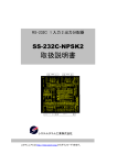
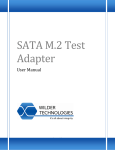
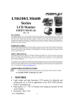
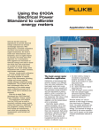
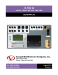
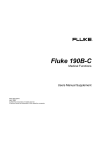
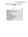
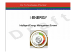
Using the 6100A Electrical Power Standard
to calibrate energy meters
Over the last few years the
significance of accurate electrical
energy calibration has become
increasingly important. With
deregulation, increased
competition and more cross
network power supply
transactions, the need to make
more measurements, more
frequently, and at a higher
degree of accuracy, has never
been more important. As a
consequence, both suppliers
and consumers of electrical
energy now need to know that
what they have distributed or
received is exactly what was
expected. As a result energy
meter calibrations have, in
most countries, now become
compulsory.
However, energy meter
calibration has, until recently,
been a task of bringing together
a complex array of test
instruments, including voltage
and current supplies, energy
reference meters and pulse
comparators. This in itself not
only has a detrimental effect on
the uncertainty of the whole
energy meter calibration
process, but is also a costly one
to introduce and maintain.
With this in mind Fluke
recently introduced the 6100A
Electrical Power Standard,
‘Energy’ option.
This application note sets out
to explain how the 6100A can
be used to accurately calibrate
energy meters without the
need for a multitude of test
equipment, thereby lowering
both testing and maintenance
costs while also optimizing the
measurement uncertainties and
accuracy.
Application Note
The basic energy meter
calibration application
Calibration of instruments that
measure energy is no different
to any other calibration. The
instrument under test is supplied
with a known quantity of the
parameter being calibrated,
and the instrument is interrogated in order to ascertain the
value of the parameter that it
has measured. This value is
then compared with the
quantity supplied, and the
measurement error is calculated.
Electricity meters, almost
without exception, use a technique of generating pulses to
indicate the amount of energy
they have measured. Each
pulse represents a specific
number of watt-hours (or VA
hours, VAR hours etc). These
pulses are transmitted from the
meter in a number of different
ways.
From the Fluke Digital Library @ www.fluke.com/library
1. On older meters, energy is
recorded by counting the
number of passes of a black
mark on the surface of a spinning metal disc.
2. By a flashing LED
3. As a direct electrical output
(Typically TTL)
4. Some of today’s newer
meters will even include highly
advanced reporting mechanisms
such as Ethernet or Bluetooth
interfaces.
Because meters are used to
measure a wide range of
energy, from watt-hours to
Gigawatt-hours, the pulses
generated can represent different
amounts of energy. This
amount of energy is specified
by the meter manufacturer, and
is known as the meter constant
(sometimes referred to as ‘k’).
For example, a specific meter
may generate 100 pulses for
every kilowatt-hour measured,
another may generate the same
number of pulses per megawatt
-hour measured. Whatever the
criteria, the calibration system
must have the ability to have
this number set within its
system in order that it can
calculate the correct quantity of
energy from the pulse count.
Energy meter calibration
methods
Calibrations are typically
performed by using a reference
measurement technique. A
known amount of energy is
simultaneously supplied to a
reference meter and to the unit
under test (UUT). A reading
from the reference meter is then
compared to a reading from the
UUT and the error is calculated.
Three separate pieces of
calibration equipment are
typically required to complete
this task.
1. An energy supply (a power
supply)
2. A reference energy meter
3. A device for counting pulses
from both the reference meter
and the UUT, which then
compares the two counts and
generates an error indication.
The block diagram of the
calibration set-up is shown in
figure 1.
Fig. 1 A typical energy meter calibration setup
In this setup, the 6100A is used
simply as the energy supply
(current supply and voltage
supply), and without the use of
any other functions available
with the 6100A’s energy option.
However, the 6100A energy
option does enable the user to
perform the calibration without
the necessity of using the
energy reference meter and/or
the pulse comparator, thereby
effectively replacing the
functionality of both instruments.
Replacing the reference
meter with a 6100A
The energy reference meter
serves two main purposes.
Firstly, it is used to provide a
reliable source of traceability,
and secondly, to measure the
amount of energy actually
delivered. The 6100A’s ability
to measure or calculate time,
means that it already knows
how much energy it has
delivered with a high degree of
accuracy. The function of the
reference meter, therefore,
becomes redundant. In this
type of setup, the comparator is
still used, but with the 6100A
now generating the pulses,
instead of the reference meter.
To mimic the ‘K’ value of the
meter under test., it is possible
to program the 6100A to generate
a specific number of pulses, per
unit of energy delivered. This
calibration setup is shown in
figure 2.
Replacing the comparator
with a 6100A
The 6100A’s ability to receive,
count, and compare pulses
means that it can also perform
all of the functions of the
comparator, effectively making
it redundant as well. The setup for this is shown in figure 3.
Fig. 2 An energy meter calibration setup using a 6100A Electrical Power Standard
2
Fluke Corporation Using the 6100A Electrical Power Standard to calibrate energy meters
Fig. 3 The 6100A Electrical Power Standard eliminates the need for comparators in the calibration setup
Replacing the reference
meter and the comparator
with a 6100A
Having established that it can
effectively replace both the
comparator and the reference
meter, the 6100A can also
combine both of these functions
together, and so replace all of
the other instruments required,
thereby allowing it to perform
the complete calibration process
on its own. This more consolidated setup is shown in figure 4.
Complex waveshapes - a
unique 6100A attribute
In the applications already
described, there is a growing
requirement to verify or
calibrate measurements under
non-sinusoidal conditions. In
fact, various standards have
been in place for a number of
years which define testing
techniques for energy meters,
and, in some cases, actually
specify detailed waveshapes
that are used for ‘type testing’
(design qualification against
standards).
One such standard is IEC 61036.
Standards around the world
vary considerably, as does their
implementation and legal
status. The waveshapes given
in figures 5, 6, 7 and 8 are all
examples specifically required
by IEC 61036, and were all
generated by a 6100A Electrical
Power Standard. The half wave
rectified signal, phase fired
signal and burst fire signal can
all be generated on either the
voltage or current channels, but
under normal circumstances
would usually be performed
using the latter. These waveshapes are easily replicated on
the 6100A’s voltage or current
channels.
The 6100A’s four testing
modes
Fig. 4 Using a 6100A Electrical Power Standard to eliminate the comparator
and reference meter, as well as a supply for both voltage and current
Fluke Corporation
When used to test, calibrate or
verify energy meters, the
6100A can be used in any one
of four testing modes. These are:
• Free running mode
• Counted/Timed mode
• Gated mode
• Energy packet mode
(also known as Dose mode)
Each offer benefits specific to
the type of test being performed.
Using the 6100A Electrical Power Standard to calibrate energy meters
3
Fig. 5 Half-wave rectified signal
Fig. 6 Phase fired signal
Fig. 7 Burst fire signal
Fig. 8 Voltage dips and short interruptions
Free running mode
In free running mode, the
6100A will not begin counting
meter pulses until the output
(OPER)ate switch is turned on.
Once the output switch is
enabled, counting will continue
indefinitely until the switch is
once again turned off.
In this mode no time constants
or energy criteria are specified.
This is particularly useful for
meter verification testing, as it
quickly establishes the condition
of the energy meter.
Free running mode is also
useful for carrying out creep
tests or even simply to make
adjustments to a meter.
Creep testing is when the
voltage coils of the energy
meter are energized with the
rated voltage, but with no
current in any current coil. The
test is performed over a specific
period of time and, fundamentally, establishes how much the
meter dial advances without
any usage by the consumer.
This is easily done using the
6100A’s basic setup user interface screens described on page
6 of this application note.
Counted/Timed mode
When the 6100A is setup in
Counted/Timed mode the user
must first enter or select data
within three panels on the
‘energy counter/time mode’
screen before counting is initiated
(see figure 9).
Fig. 9 Energy Counter/Timer mode configuration screen
4
Fluke Corporation Using the 6100A Electrical Power Standard to calibrate energy meters
Firstly, a warm-up time can
be specified. This allows the
user to run the meter for a
user-definable period of time,
so that the energy meter can
reach a suitable operating
temperature, prior to testing.
Then, the test period criteria
must be selected. This panel
incorporates three selection
criteria:
1. Derivation
2. Duration
3. Pulse source
The selection made within
the ‘Derivation’ drop down
menu determines the way the
6100A delivers the energy
required. This can be specified
in either time, pulse counts, or
as a measure of energy.
The ‘duration’ entry is
merely a length or period of
time, dependent upon the
selection made within the
‘Derivation’ drop down menu.
This will be specified as either
a time in seconds, minutes or
hours, a number of counts, or
Watt hours (stated in either
Watt hours, kilo Watt hours or
Mega Watt hours).
Having chosen the method
in which energy is delivered, a
pulse source must then be
chosen. This will identify which
channel, or channels, on the
6100A are used to input the
counting pulses from the
energy meter. It is worth noting
at this point that with six
channels, the 6100A is also
capable of testing multi-phase
energy meters with multiple
pulse outputs, as well as those
with a single pulse output.
Finally, an ‘Energy Gate
In/Out’ socket on the rear of
the 6100A can be enabled and
then configured according to
the user’s requirements.
Having enabled the ‘Energy
Gate Out’ function, the operator
can select the signal types as
either a signal consisting of a
level to the required duration
or as a start and end pulse.
This can also be either active
high or low. Lastly, the source
impedance of the internal pullup resistor can be specified as
either 150 Ω or 1 kΩ, to match
the meter or monitoring system’s
own source impedance. This
should be determined from the
equipments own user manual
prior to connecting to the 6100A.
Gated mode
In Gated mode the user has the
opportunity to remotely activate
the 6100A’s output and counting
cycle. This is achieved by
applying an ‘active’ signal to
the 6100A’s ‘Energy Gate In/Out
Connector’ on the rear panel.
This connector automatically
becomes an input socket when
the gated mode is selected.
However, before testing can
begin, the parameters of the
‘active’ signal being used must
first be configured within the
6100A’s ‘Energy Gated Mode
Configuration’ screen (see figure
10). Here, the signal type,
active signal level and internal
pull-up parameters must initially
be set-up. Details on how to do
this can be found in the 6100A
user manual.
Having completed this process,
the 6100A now requires the
user to enter the length of the
test period, in readiness to
switch either the output or
counting function on and off
from an alternative piece of test
equipment or system with
‘active’ signal capability. This
could be a PC set up with the
users own dedicated software
program, designed specifically
to give arbitrary time, energy or
count control of the 6100A.
Fig. 10 Energy Gated mode configuration screen
Fluke Corporation
Using the 6100A Electrical Power Standard to calibrate energy meters
5
Energy packet mode
In energy packet mode, also
known as dose mode, the
power from the output terminals
is timed to deliver the requested
amount of energy to the meter
under test. This can be defined
as either energy, counts or time.
However, unlike Counted/
Timed mode, there is no warmup period. This is advantageous
to those wishing to eliminate
initial dial advance on the
meter under test. Dial advance
is when both the reference
meter and meter under test
advances more than the measured amount on the 6100A.
This is perfectly normal and
represents settling and warm-up
times included in the test.
Furthermore, please note that
when using the 6100A’s other
modes, the actual test duration
and count to achieve the
displayed result is perfectly
accurate. In energy packet
mode dial advance does not
become an issue as there is no
warm-up period.
As with other modes, the
mode’s own configuration
screen must be setup prior to
testing. See Figure 11.
The 6100A’s user
interface and basic setup
The 6100A’s energy user interface can be accessed via the
waveform menu. Note: If
accessed directly from power-up,
then the ‘Esc’ key on the keyboard must be pressed first.
Here, a softkey labeled ‘Energy
Counting’ can be found. Upon
selecting this key, the user
must then configure the 6100A
according to his test setup. This
can be done by selecting the
softkey ‘Configure Meter Constants’,
which in turn accesses the
‘Channel Configuration and
Meter Constants’ screen (see
figure 12).
The first panel, ‘MUT Source’,
determines which sockets on
the front panel of the 6100A
are being used as energy pulse
inputs.
6
Fluke Corporation
Fig. 11 Energy packet mode configuration screen
A number of different configurations can be setup in this
panel, from one to six single
phase meters, or even a single
pulse three phase meter (The
‘Sum of Channel 1,2 and 3’
check box).
Having identified the pulse
source channel(s), the user
must then select the reference
source. This will depend upon
which circuit (as shown in
figures 2, 3 and 4) the user has
chosen to perform the tests. If
the 6100A’s internal reference
is being used, as shown in
figure 4, the check box ‘Main
Output’ must be selected.
Alternatively, if either an external
single phase or three phase,
meter are utilized as a reference,
then one of other five check
boxes must be selected, according
to the test setup being used. Two
such examples are shown in
figures 1 and 3.
The ‘Meter Constant Base’
drop-down menu allows users
to select any one of three
meter base units, depending
upon the meter being tested —
Wh (Real power), VAh
(Apparent power or VARh
(Reactive power). Having
selected this, the meter constants
must then be specified. This
must be done for both the meter
under test, the external energy
reference meter (if used) and
finally, the reference pulse output
of the 6100A. For both the ‘Meter
Constant (MUT)’ and ‘Meter
Constant (Reference)’ panels, this
will be entered according to the
output specifications of the meter
under test and external energy
reference meter (if used).
Using the 6100A Electrical Power Standard to calibrate energy meters
In the case of the ‘Meter
Constant (Output)’ panel, a value
can be set which specifies the
effective meter constant of the
‘Pulse Out’ connector. Whenever
an energy test is active, this
output is a pulse stream
representing the total power
and energy of the active V/I
outputs of all 6100A/ 6101A’s in
the system.
There are also internal user
selectable pull-up resistors for
pulse inputs. This is particularly
useful for meters with opencollector outputs. A separate pullup resistor is associated with
each meter constant.
For the meter under test and
reference meter, these can be
selected as either 150 Ω or
1 kΩ. Similarly, a user selectable
internal pull-up is provided for
the main output’s energy pulse
output. This can be selected or
deselected using the ‘Use
Internal pull-up’ check box.
Fig. 12 Channel Configuration and Meter Constants screen
The basic setup is now
complete. The user can now
enter the required combinations
for L1 (L2 and L3 if using a two,
three or four phase system) via
the 6100A’s output menu.
Now the meter testing is ready to
begin. To start the test the user
simply presses the 6100A’s
green ‘OPER’ button — unless in
‘Gated mode’, whereupon the
6100A’s ‘OPER’ button must first
be pressed, before the 6100A
can identify the appropriate gate
signal to begin the test. A typical
output menu screen when
running a full test can be seen in
figure 13.
At this point it is worth noting
that the 6100A can only be used
with devices that have a provision
for independent (auxiliary) power
for their internal circuits. The task
of the 6100A is to accurately
maintain its voltage output at the
shape and level demanded by
the user for a wide range of
loads. The 6100A cannot maintain
its precision output if loaded by
the short-term cycle by cycle
variations in current demanded
by the meter under test’s power
supply units.
Typical 6100A energy
applications
Energy meter testing typically
falls into one of three categories:
• In service testing/calibration
• Manufacturing testing
• Type testing/approval
In service testing/calibration
In service testing/calibration is
where energy meters already
in the field are brought in at
regular intervals for verification
and/or calibration. This regime
varies from country to country,
however in most cases energy
meters will be batch tested in a
meter shop, several meters at a
time. This is particularly
prominent in some countries
where state law dictates that
consumer energy meters must
be tested each year. With this
in mind, these countries have
meter testing shops in abundance.
Clearly, to get through such
numbers in one year requires
batch testing on a large scale.
To overcome this, several
energy meters are wired into
vast meter testing arrays with
multiple sensors. Smaller arrays
can test ten meters simultaneously.
Fluke Corporation
In some countries, this
number can rise to one hundred
and beyond. There may be
many advantages to testing
meters in this way — not least
the high numbers that can be
tested at one time. However,
there are several disadvantages
too. The greatest one being the
amount of power required to
carry out such tests. Plainly,
this type of application, on
power alone, is outside the
6100A’s, or any of its configured systems, intended workload. However, that said, it is
also becoming common for
such meter shops to employ a
‘specials’ test rig. This type of
versatile test rig is designed to
accommodate other such energy
meters that for one reason or
another cannot be tested in the
larger arrays. This may be due
to physical size, unique environment requirements or even for
non compatibility reasons. For
such lower denomination test
rigs the 6100A is ideal. Power
requirements are a lot lower
and the number of input
channels required to perform
the tests is easily within even a
single 6100A’s capability.
Using the 6100A Electrical Power Standard to calibrate energy meters
7
Manufacturing testing and
Type testing/approval
Meter manufacturers are using
6100A’s and 6100A systems
for meter type testing and
approval work, within their
own design centers and
engineering development groups.
With a multitude of new and
differing standards, all with
several derivations from
country to country, regularly
being introduced around the
world, the 6100A is being
recognized as the only single
box solution that can replicate
and test them all. Furthermore, it
can do so with the highest
accuracy and traceability.
For the energy meter
manufacturers this whole new
philosophy of type testing and
approval was driven primarily
by their customers — utility
companies (and other similar
operators) and the regulatory
agencies associated with them.
Now, all of these organizations
use the 6100A to test their
energy meters prior to deployment, to verify them before use
into a new installation. However,
these very same companies
and organizations are now also
using the 6100A to verify existing
meters in the field, particularly
in circumstances of dispute.
Fig. 13 The 6100A’s Output Status screen
With several different ‘type
testing’ applications around the
world, most users see it as a
means to verify, calibrate or
design their energy meters for
type approval. In many countries,
conforming to the necessary
standards has become a legal
requirement
Fluke 6100A Electrical Power Standard
In Europe meter manufacturers,
utility companies and external
regulatory agencies all adhere
to the requirements of IEC
61036. In other parts of the
world, similar standards exist
and consequently dictate the
way energy meters are both
manufactured and applied.
Fluke. Keeping your world
up and running.
Fluke Corporation
PO Box 9090, Everett, WA USA 98206
Fluke Europe B.V.
PO Box 1186, 5602 BD
Eindhoven, The Netherlands
For more information call:
In the U.S.A. (800) 443-5853 or
Fax (425) 446-5116
In Europe/M-East/Africa (31 40) 2 675 200 or
Fax (31 40) 2 675 222
Canada (800)-36-FLUKE or
Fax (905) 890-6866
From other countries +1 (425) 446-5500 or
Fax +1 (425) 446-5116
Web access: http://www.fluke.com/
©2004 Fluke Corporation. All rights reserved.
Trademarks are the property of their respective owners.
Printed in UK 02/2004 2130388 A-ENG-N Rev A, DS272
The most accurate, comprehensive and flexible
source of electrical power signals
Fluke Corporation
Using the 6100A Electrical Power Standard to calibrate energy meters