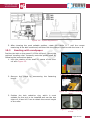
1
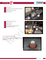
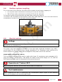
USE AND MAINTENANCE MANUAL c .i v r e f m o 2 in 1 Spindle moulder and spindle sander Art. 0559 TRANSLATION OF THE ORIGINAL INSTRUCTIONS MACHINES AND ACCESSORIES PREFACE Please ensure you have read this manual before operation TRANSLATION OF THE ORIGINAL INSTRUCTIONS Reading this instruction manual is required before operating any of the machinery. The guarantee that the machine will function and perform properly is strictly dependent upon the application of all the instructions contained in this manual. m o Operator Qualifications c .i The workers responsible for the use of this machine must have all the necessary information and instruction and should be given adequate training in relation to safety regarding: a) Conditions of use for the equipment; b) Foreseeable abnormal situations, pursuant to Article 73 of Legislative Decree 81/08. e f v r We guarantee the Machine complies with the specifications and technical instructions described in the Manual on the date of issuance and listed herein; On the other hand, the machine may also be subject to important technical changes in the future, without the manual being updated. Therefore, contact FERVI for information about modifications that may have been implemented. REV. 1 Page 2 of 50 August 2013 MACHINES AND ACCESSORIES CONTENTS 1 INTRODUCTION ........................................................................................ 5 1.1 2 Preface..........................................................................................................................6 SAFETY WARNINGS .................................................................................. 7 2.1 General safety regulations ............................................................................................7 2.2 2.1 General Electric Power Tool Safety Standards....................................................... 10 2.3 Technical assistance ................................................................................................... 10 2.4 Other provisions ......................................................................................................... 10 m o 3 TECHNICAL SPECIFICATIONS ................................................................. 11 4 DESCRIPTION OF THE MACHINE ............................................................. 12 4.1 Main parts of the machine........................................................................................... 14 4.1.1 Optional accessories ................................................................................................. 15 c .i 4.2 Identification plate ..................................................................................................... 16 4.3 Pictograms .................................................................................................................. 16 5 DESCRIPTION OF CONTROLS .................................................................. 18 5.1 Emergency stop and start/stop button ....................................................................... 18 5.2 Shaft locking lever ...................................................................................................... 19 5.3 Spindle handwheel and lever ...................................................................................... 19 6 v r MACHINE SAFETY DEVICES ..................................................................... 20 6.1 Electrical safety devices .............................................................................................. 20 6.2 Safety devices against "mechanical" risks .................................................................. 20 6.3 Use of PPE................................................................................................................... 22 e f 7 MISUSE AND CONTRAINDICATIONS ....................................................... 23 8 TRANSPORT AND LIFTING ...................................................................... 24 9 ASSEMBLY AND COMMISSIONING .......................................................... 25 9.1 Machine delivery and unpacking ................................................................................. 25 9.2 Assembling the machine ............................................................................................. 25 9.3 Positioning and installation of the machine ................................................................ 26 9.4 Suction system coupling ............................................................................................. 27 9.5 Electric wiring ............................................................................................................. 27 10 OPERATION .......................................................................................... 29 10.1 Instructions for Use ................................................................................................. 29 10.2 Straight milling ........................................................................................................ 30 10.2.1 Adjusting the guards ................................................................................................ 31 10.2.2 Adjusting the rotation speed...................................................................................... 32 Page 3 of 50 MACHINES AND ACCESSORIES 10.3 11 Sanding with sandpaper .......................................................................................... 33 MAINTENANCE ..................................................................................... 35 11.1 Routine maintenance ............................................................................................... 35 11.2 Lubrication............................................................................................................... 36 11.3 Adjusting the table .................................................................................................. 36 11.4 Replacing the sandpaper.......................................................................................... 36 12 REPLACEMENT PARTS........................................................................... 38 13 WAREHOUSE STORAGE......................................................................... 47 14 DISPOSAL OF PARTS AND MATERIALS ................................................. 47 15 TROUBLESHOOTING ............................................................................. 48 16 WIRING DIAGRAM ............................................................................... 50 v r c .i e f Page 4 of 50 m o MACHINES AND ACCESSORIES 1 INTRODUCTION This manual is considered an integral part of the machine it was attached to at the time of purchase. The manufacturer holds all ownership to material and intellectual property of this manual; any disclosure or copying, even partial, of this publication without prior written consent is forbidden. This manual is designed to provide the knowledge required for the use and maintenance of the ToupieArt. 0559 and to provide the operator assigned to the device with a sense of responsibility and knowledge of its possibilities and limitations. m o As the machine is entrusted to experienced and skilled operators, the following machine must be perfectly known by the operator if you want it to be used safely and effectively. Operators must be properly trained and prepared, so make sure that this manual is read and consulted by the staff responsible for commissioning, operation and maintenance of the Single shaft vertical milling machine (Toupie). This is to make all operations the safest and most effective possible for those who carry out these tasks. c .i Therefore, it is imperative to strictly comply with the requirements in this manual, a necessary condition for safe and satisfactory operation of the machine. Before starting operation, installation and use of the Toupie, authorized staff must therefore: v r read this technical document carefully; know which protections and safety devices are available on the machines, their location and how they work. e f The buyer is responsible for ensuring that users are properly trained, that they are aware of all the information and instructions in this document and that they are aware of the potential risks of operating the Toupie. The manufacturer waives any and all responsibility for damage to people and/or things caused by non-observance of the instructions in this manual. Page 5 of 50 MACHINES AND ACCESSORIES The Toupie has been designed and built with mechanical guards and safety devices designed to protect the operator/user from possible injury. It is strictly forbidden to modify or remove guards, safety devices and caution labels. If you do so temporarily (for example, for the purposes of cleaning or repair), make sure that no one can use the machine. Modifications to the machines carried out by the user must be considered their sole responsibility, therefore the manufacturer declines all responsibility for any damage caused to persons and/or property resulting from maintenance performed by unqualified personnel and in a manner different from the operating procedures shown below. m o Graphic representation of safety, operational and risk warnings The following boxes are designed to attract the attention of the reader / user for the proper and safe use of the machine: Pay Attention c .i This highlights behavioural rules to prevent damage to the machine and/or the occurrence of dangerous situations. Residual Risks v r This highlights the presence of dangers that cause residual risks to which the operator must pay attention in order to avoid injury or damage to property. 1.1 Preface For safe and easy operation of the Toupie, this manual must be read carefully in order to acquire the necessary knowledge. In other words, durability and performance are strictly dependent on how it is used. Follow the instructions contained herein, in addition to the general precautions to be observed while working. Even if the operator is already familiar with the Toupie, it is necessary to: Acquire full knowledge of the machine. Read this manual carefully to understand: operation, safety devices and all necessary precautions. All this is to allow safe use of the machine. Wear appropriate clothing for the job. The operator must wear appropriate clothing to prevent the occurrence of unforeseen accidents. Maintain the machine with care. e f Using the Machine The machine must only be used by qualified personnel trained to use the machine by authorized personnel. Page 6 of 50 MACHINES AND ACCESSORIES 2 SAFETY WARNINGS 2.1 General safety regulations Accident There is always a risk of injury during milling operations due to accidental contact of body parts with the moving tool, flying debris from the workpiece, tool breakage or ejection of a badly blocked workpiece. There is no "intrinsic" means of safety, just as there is no worker who, while careful, can "always" avoid an accident. Therefore, DO NOT underestimate the risks associated with using the machine and concentrate on the work in progress. m o Risks related to Using the Machine c .i DO NOT underestimate the risks associated with using the machine and concentrate on the work in progress. Risks associated with using the machine v r Despite the implementation of all the safety devices for safe use of the machine, it is necessary to take note of all the requirements for the prevention of accidents reported in various parts of this manual. Risks related to Using the Machine e f Every person who is responsible for the use and maintenance of the machine should have first read the instruction manual, particularly the chapter on safety information. It is recommended that the plant safety manager get written confirmation of the above. Operator Protection Before starting any type of work on the machine, the operator must wear appropriate personal protective equipment (PPE) such as goggles, gloves and safety shoes. 1. Read this manual carefully, in order to work safely. 2. Always check the efficiency and integrity of the machine. 3. Keep your working area clean to prevent damage. 4. Do not start the machine in an enclosed or poorly ventilated area, or in the presence of a flammable and/or explosive atmosphere. Do not use the machine in damp and/or wet locations, or those exposed to rain. 5. Beware of electric shocks. Avoid the body from coming into contact with floor surfaces or the ground. 6. Avoid starting accidentally. 7. Make sure that your work environment is forbidden to children, strangers and animals. 8. Before starting the machine, get used to ensuring that no remaining maintenance and service keys are inserted. Keep the workplace tidy. Page 7 of 50 MACHINES AND ACCESSORIES 9. Do not force the machine. Use tools appropriate to the seriousness of the job. 10. Do not perform tasks on the machine other than those for which it was designed. Only use the machine in the manner in which it was intended, as described in this instruction manual. 11. Always wear eye protection and protective gloves while working. If dust is produced, use the appropriate masks. 12. Wear appropriate clothing. Loose clothing, dangling jewellery, long hair, etc., can get caught in the moving parts, causing irreparable injury. 13. Keep the workplace tidy and free from obstruction; disorder causes accidents. 14. Always connect the suction equipment for sawdust. 15. Do not pull the power cord to detach it from the socket. Keep it away from heat, oil or sharp edges. 16. Always work in safety. Take all precautions to avoid accidental contact with the moving parts. 17. Periodically check the stability of the machine. 18. Maintain the machine with care and clean in its entirety. Keep cutting tools clean and sharp. Follow the instructions for lubricating and changing accessories. Periodically check the condition of the power cables. 19. Replace worn and/or damaged parts, check that the repairs and protection devices work properly before operating. If necessary, have the machine checked by the service support personnel. Use only original spare parts. 20. Check the machine for damaged parts. Before you use the machine after the replacement/repair of parts you need to check that it is working properly. Check the alignment and connection of moving parts, failures, correct assembly. 21. Pay maximum attention to what you are doing and use common sense when you use the machine. Use the machine only when in good physical condition (never when you are tired). 22. The use of accessories or devices other than those recommended in this instruction manual and may pose a risk to the safety of the operator. 23. Repairs may only be carried out by qualified and authorised personnel. 24. Do not use the machine if the protection devices are not in their designated position and correctly adjusted. 25. Do not use blades which are not sharpened because this increases the risk of rejection (return back) of the workpiece. 26. Position the guards and piece guide tables so as to only leave uncovered the portion of the tool actually required. 27. Always use the appropriate piece guide device supplied to push the workpiece. It is safer than using your hands! 28. Do not use the machine to make grooves. 29. The effectiveness of the workpiece anti-rejection device should be checked periodically. 30. Remain balanced whilst working. 31. Work areas must be well lit. 32. Do not move away from the machine until the tools and other moving parts, have completely stopped. For this purpose, only use the stop controls to stop the machine. 33. Unplug the power cord of the machine from the power outlet when: the machine is not being operated; it is left unattended; performing maintenance or registration, because the machine does not work properly; the power cable is damaged; replacing the cutting tool; it is being moved or transported; cleaning. v r c .i e f Page 8 of 50 m o MACHINES AND ACCESSORIES 34. It is recommended that users of this publication, for maintenance and repair, have a basic knowledge of the mechanical principles and procedures inherent in repair technique. 35. The company safety officer is required to make sure that machine operators have read and understood this manual in its entirety. 36. The company safety manager is responsible for monitoring the company's risk status according to Legislative Decree no. 81/08 and subsequent modifications and amendments. c .i v r e f m o Page 9 of 50 MACHINES AND ACCESSORIES 2.2 2.1 General Electric Power Tool Safety Standards Changes to the electrical system Do not modify the machine's electrical system in any way. Any attempt to do so may impair the operation of the electrical devices causing a malfunction or accident. Work on the electrical system of the machine must therefore be carried out only by qualified and authorised personnel. If you hear unusual noises, or notice something strange, immediately stop the machine. Then carry out an inspection and, if necessary, perform any repairs as required. m o 1. Ensure supply voltage complies with the label and technical specifications (230 V / 50 Hz). Never use any other type of power supply! 2. The use of a life-saving device on the electric power supply for a nominal trip range of 10 to 30 mA is recommended. For more detailed information, contact a trusted electrician. 3. The mains power outlet should be bipolar grounded (10/16 A, 250 V), extension cables must have sections that are the same or greater than the sections of the power cable of the machine. 4. Make sure that the power cord does not come into contact with hot objects, wet or oiled surfaces, and/or sharp edges. 5. The power cord should be checked regularly and before each use to check for signs of damage or wear. If these are not in good condition, do not use the machine and replace the cable. 2.3 v r c .i Technical assistance For any problems or concerns, please do not hesitate to contact the dealer who sold you the machine. 2.4 e f Other provisions IT IS FORBIDDEN TO TAMPER WITH SAFETY DEVICES Check the presence and integrity of protections and the proper functioning of safety devices before starting operation. If any defect is encountered do not use the Toupie! It is strictly forbidden to modify or remove guards, safety devices, labels and caution signs. Page 10 of 50 MACHINES AND ACCESSORIES 3 TECHNICAL SPECIFICATIONS Description 0692/230V 0692/400V Height (mm) 1106 Length (mm) 800 Depth (mm) 885 m o Table (mm) 600 x 400 Table height (mm) 850 Rated voltage (V) 230 Power (W) c .i Frequency (Hz) Rotation speed (rpm) Suction hole diameter (mm) Useful height of tool holder shaft (mm) v r Vertical tool stroke (mm) 1,500 50 1500 - 4000 - 6000 Maximum bore diameter of the table (mm) Spindle diameter (mm) e f Net weight (kg) 100 105 80 144 30 98 Acoustic pressure level at operator's workstation LpA (dB)* Unloaded Under load 82 90 Acoustic power level LwA (dB)* Unloaded Under load 95 103 * The measurement of acoustic emissions was performed in agreement with that reported in Appendix B of ISO 7960. Page 11 of 50 MACHINES AND ACCESSORIES 4 DESCRIPTION OF THE MACHINE The SINGLE SHAFT VERTICAL MILLING MACHINE - TOUPIE (Art. 0559) is a machine designed for milling / shaping wooden planks. During milling, the wooden plank is placed on the table according to the desired inclination and is fed laterally towards the rotating tool. The machining depth is adjusted by positioning the piece guide tables so as to leave a bigger or smaller portion of the tool according to the cutting depth. The processing height is changed by adjusting the vertical movement of the tool holder spindle. The machine is designed and built for the processing of wooden planks, curved processing is not envisaged nor is there a section for the processing of glass. m o Tools and milling cutters of various types can be mounted onto the spindle for work involving the hollowing, drilling and milling of wood. Other types of use, or the extension of use beyond that envisaged, does not correspond to the designation attributed by the manufacturer, and therefore the latter cannot accept any responsibility for any damage resulting therefrom. c .i Intended use and materials The machine was designed and manufactured for a specific use, different uses and noncompliance with technical parameters established by the Manufacturer may be hazardous to the operator. In particular, with regard to the type of material, DO NOT use the machine for non-wood materials. v r e f The Toupie consists of: main frame; work table, adjustable guide; electric motor and its relative transmission components; shaft and tool holder spindle; on and off buttons and adjustment devices. Refer to paragraph 4.1 of this manual to view the different parts of the machine in detail. The motor operates at constant speed, the rotation speed of the tool can be set at three different positions, changing the position of the belt on the pulleys. The Toupie must be installed and used on a flat, stable surface of adequate strength. The Toupie is designed and intended for use in enclosed workplaces (production departments, warehouses, etc.). The best performance levels can be obtained only if certain conditions are met: use within the temperature range from -5 to +40°C; relative humidity from 30% to 95%, non-condensing; height above sea level max. 1000 m. Page 12 of 50 MACHINES AND ACCESSORIES The environment must also be sufficiently illuminated, so as to ensure operation in maximum safety (at least 200 lux is recommended). SUCTION SYSTEM The machine must be connected to a dust suction device before each use. The suction device must have an air flow with a minimum speed of 20 m/s for dry shavings and at least 28 m/s for wet shavings. The diameter of the suction hose coupling should be about 10 cm. The suction hose must be connected to the suction nozzle mounted behind the tool guard. m o It is important to respect the environment: dispose of any shavings in compliance with current legislation. e f v r c .i Page 13 of 50 MACHINES AND ACCESSORIES 4.1 Main parts of the machine 2 m o 4 3 1 9 c .i 7 v r 8 e f 5 6 Figure 1 – Spindle moulder Art. 0559. 1 Work table 6 Start / Stop buttons 2 Adjustments of the protection device “1” 7 Motor / pulley compartment 3 Shaft protection guard 8 Base 4 Lateral guide 9 Lateral guide 5 Tool height adjustment Page 14 of 50 MACHINES AND ACCESSORIES 10 Work table 11 Adjustments of the protection device “1” 12 Shaft protection guard 13 Lateral guide 12 10 11 m o 13 Figure 2 – Sliding table. 14 Shaft protective cover 15 Guide clamp 16 Table clamp 17 Protection guard locking lever 18 Output piece guide v r e f 4.1.1 Optional accessories c .i The machine can be equipped with an optional accessory for sanding with sandpaper. 17 14 16 15 18 Figure 3 – Tool holder guard. Figure 4 – Sanding roller Page 15 of 50 MACHINES AND ACCESSORIES 4.2 Identification plate The identification plate shown below is attached to the machine: 4.3 m o Pictograms ATTENTION 1. 2. 3. 4. 5. 6. 7. 8. 9. 10. 11. 12. 13. 14. c .i Please read the instructions before using the machine. The operator must have adequate knowledge and familiarity of the machine before use. The machine must be securely fixed to the floor before use. Wear appropriate clothing and eye protection. Wear ear protection if necessary. Do not use the machine without the safety guards. The maintenance and adjustments must be performed by skilled and experienced personnel. Do not carry out any adjustments while the machine is in motion. Only use the machine when it is running smoothly. Never force the material during processing. When using the machine, the motor should run smoothly without strain. Keep fingers and hands away from blades. When performing any adjustment or replacement of parts, remove the plug from the socket. For further information on safety, please consult the instruction manual. e f v r Figure 5 – Warning pictograms. Page 16 of 50 MACHINES AND ACCESSORIES Legend: PLATE IN ITALIAN 1. 2. 3. 4. 5. 6. 7. 8. 9. 10. 11. 12. 13. 14. PLATE IN ENGLISH ATTENZIONE!! Leggete attentamente le istruzioni prima di utilizzare la macchina. L’operatore deve avere un’adeguata conoscenza e familiarità della macchina prima dell’uso. La macchina deve essere adeguatamente fissata al pavimento prima dell’uso. Indossate indumenti appropriati e occhiali protettivi. Indossate cuffie antirumore, se necessario. Non usate la macchina senza le protezioni antinfortunistiche. La manutenzione e le regolazioni devono essere eseguite da personale competente ed esperto. Non effettuate regolazioni quando la macchina è in moto. Usate la macchina solo quando gira regolarmente. Non forzate mai il materiale durante le lavorazioni. Quando usate la macchina il motore deve girare regolarmente senza forzare. Tenete le dita e le mani lontano dai coltelli. Quando eseguite lavori di regolazione o sostituzioni di parti, togliete la spina della presa di corrente. Si consiglia di consultare il manuale d’istruzione per altre indicazioni sulla sicurezza. 1. 2. 3. 4. 5. 6. 7. 8. m o c .i v r e f ATTENTION!! Please read the instructions before using the machine. The operator must have adequate knowledge and familiarity of the machine before use. The machine must be securely fixed to the floor before use. Wear appropriate clothing and eye protection. Wear ear protection if necessary. Do not use the machine without the safety guards. The maintenance and adjustments must be performed by skilled and experienced personnel. Do not carry out any adjustments while the machine is in motion. Only use the machine when it is running smoothly. Never force the material during processing. When using the machine, the motor should run smoothly without strain. Keep fingers and hands away from blades. When performing any adjustment or replacement of parts, remove the plug from the socket. For further information on safety, please consult the instruction manual. 9. 10. 11. 12. 13. 14. Page 17 of 50 MACHINES AND ACCESSORIES 5 DESCRIPTION OF CONTROLS 5.1 Emergency stop and start/stop button On the edge of the machine in correspondence with the piece inlet table of the workpiece, there are start, stop and emergency stop buttons (a), a cap that covers the two buttons (see Figure 6). To start the machine it is necessary to open the yellow door (a) and press the green start switch (b). Conversely, to stop the machine press the red stop switch (c). Once the machine has been started, move the yellow door towards its closed position, without completely shutting it. In the event of danger, press the emergency stop button (ref. a). In this case the door closes completely, leading to the pressing of the stop switch (c). m o c .i F v r C B A e f E D Figure 6 – Spindle moulder commands Risk of injury It is absolutely forbidden to by-pass the safety device established by the emergency stop button and its circuitry. Risk of injury Before starting the spindle moulder, make sure all the guards are properly positioned and tightly fixed. When the start switch is pressed, the shaft starts to rotate immediately, and with it the tool holder spindle. Do not leave unused tool mounted on the spindle. Page 18 of 50 MACHINES AND ACCESSORIES Risk of injury It is absolutely forbidden to by-pass the safety device established by the emergency stop button and its circuitry. Emergency m o In the event of danger, press the emergency stop button. 5.2 Shaft locking lever The lever is positioned to the right of the machine (ref. d in Figure 6). The lever is used to lock the rotation of the shaft when replacing the tool on the spindle. c .i Motor breakdown Do not start the machine when the shaft has been locked with the locking lever, the motor could operate under strain and burn out. 5.3 v r Spindle handwheel and lever The handwheel for vertical positioning and the clamping lever for the spindle are located on the right part of the machine (ref. e and f in Figure 6). Turn the handwheel clockwise to lower the tool, turn the wheel anticlockwise to raise the tool. Turn the lever to the right (clockwise) to tighten the shaft, turn the lever to the left (anticlockwise) to release the shaft. e f Shaft damage Always remember to release the shaft by means of the lever f, before operating the handwheel. Page 19 of 50 MACHINES AND ACCESSORIES 6 MACHINE SAFETY DEVICES 6.1 Electrical safety devices In the event of malfunction or breakdown, the Toupie is equipped with power cable and plug with grounding conductor, which provides a path of least resistance for electric current and reduces the risk of electric shock. The plug must be plugged into an appropriate socket, grounded in accordance with current regulations, the line must be fitted with a suitable system for the automatic disconnection of the power supply, coordinated with the electrical system of the machine. The power cord should be at least 1.5 mm thick with reinforced insulation (e.g. HO7), and at least 2.5 mm thick if it has a length exceeding 10 m. Extension cords must be of a section equal to or greater than that envisaged for the power cord of the machine. Electric shock m o c .i It is absolutely forbidden to by-pass the safety device established by the emergency stop button and its circuitry. Check with a qualified electrician if you don't understand the grounding instructions or if you have any doubts about grounding the machine. The machine is also equipped with a micro-safety switch connected to the pulley compartment door, which stops the power supply when the door is opened. 6.2 v r Safety devices against "mechanical" risks PROTECTIVE CASING OF THE MOTION TRANSMISSION COMPONENTS The protective casing prevents the operator's body parts, particularly hands and/or fingers, from coming into direct contact with the transmission components of the machine, when it is activated. e f Casing Position Check Each time the Spindle moulder is used, check that the protective casing is perfectly positioned and securely fixed. Access to the speed change pulleys, is achieved via an interlocked door, the machine stops as soon as it is opened. Figure 7 – Pulley compartment Page 20 of 50 MACHINES AND ACCESSORIES Accidents Always turn off the machine and wait until the spindle has stopped before opening the pulley compartment access door. Tool holder shaft guards The spindle guard is composed of removable equipment, equipped with adjustable parts and fixed parts. It should be installed on the machine and adjusted according to the size of the tool and the workpiece. m o c .i Figure 8 – Tool guard. v r These guards prevent splinters or fragments of pieces that may come loose, from being thrown into the operator's face, but above all are to prevent the the operator from coming into direct contact with the rotating cutting tool. The guard is equipped with fixing and adjustment knobs, to better adapt to the dimensions of the workpiece. e f Repair Control Each time the Spindle moulder Art. 0559 is used, check that the protective tool guards are perfectly positioned and securely fixed. Cutting of hands and/or fingers IT IS STRICTLY FORBIDDEN to use the machine without guards and/or put your hands near the tool. Use the appropriate piece guide device supplied to push the workpiece. "Piece guide" lever The piece guide lever guides the workpiece to be milled towards the tool, so as to avoid the hazard of hands being too close to the blade in motion especially when the workpieces are small. Page 21 of 50 MACHINES AND ACCESSORIES Emergency stop button The Toupie is equipped with an emergency stop button located above the Start / Stop buttons (see Figure 6). In the event of danger it guarantees a rapid shutdown of the machine and its moving parts. Emergency stop Activate the emergency stop button in the event of danger and/or breakdown of the machine. 6.3 m o Use of PPE Even if the machine is equipped with safety devices, there are dangers of injury related to the execution of the work. It is a good idea for the operator before starting to work, to put on Personal Protective Equipment: wear glasses or a protective mask to prevent chips, dust or other parts from damaging your eyes or face; to protect your hands from splinters on the workpiece wear gloves; the Toupie has a noise level of 80 dB, therefore the operator must wear ear protection devices such as earmuffs or earplugs; use suitable clothing at work, close-fitting and free of dangling parts. v r c .i Use of PPE. ALWAYS use appropriate personal protective equipment (PPE), such as: Gloves, Goggles or face shields; Ear muffs or ear plugs; Overalls or aprons; Safety shoes. e f Figure 9 - Personal Protective Equipment. Page 22 of 50 MACHINES AND ACCESSORIES 7 MISUSE AND CONTRAINDICATIONS The following actions, which obviously cannot cover the entire range of possible "misuse" of the machine are strictly forbidden. THE FOLLOWING IS STRICTLY PROHIBITED! To use the machine for working with non-wood materials; To hold the workpiece by hand; To use the machine without protective cover or with the cover open; To push the piece by hand, without the aid of the piece pusher device; To use the machine for purposes other than those for which it was designed; To exceed the working capacity stated by the manufacturer. To leave the machine unattended with the plug inserted. To allow untrained staff to use the machine; To operate this machine if you are not psychophysically fit; To use the machine without due attention; To use the machine without the use of appropriate personal protective equipment, such as safety shoes and gloves, goggles or shields, ear muffs, etc.; To use the machine in unforeseen environmental conditions (weather, high magnetic fields, etc.); To use the machine without connecting a suitable dust suction system; To use the machine in potentially explosive atmospheres; To use the machine in inadequate light; To let the machine come into contact with foodstuffs; To tamper with equipment and/or safety devices; To tamper with the electrical circuit. c .i v r e f m o Page 23 of 50 MACHINES AND ACCESSORIES 8 TRANSPORT AND LIFTING The weight of the Toupie is 100 kg, therefore it can only be lifted and transported using equipment suitable for the task. The optimum solution for handling is to use a pallet truck or a forklift truck with sufficient capacity. To carry out the lifting of the Toupie steel ropes must be used with a diameter greater than 5 mm. To do so, follow the instructions below: disconnect the power plug from the outlet and pick up the cable, making sure that will not be damaged during transport; secure all the parts of the Toupie in order to prevent unexpected movement of moving parts; after verifying that the equipment is properly secured, carefully begin lifting. m o c .i Machine transport All transport operations must ALWAYS be carried out when the machine is stopped and no metal pieces are on the machine table. ALWAYS disconnect the power plug. v r e f Page 24 of 50 MACHINES AND ACCESSORIES 9 ASSEMBLY AND COMMISSIONING 9.1 Machine delivery and unpacking The Toupie is supplied partially disassembled. The machine is packed (fixed securely with pins) on a wooden pallet. Before disposing of packaging, check that no parts of the machine, including the user manual or other documentation, are going to be thrown away. How to remove packaging: remove the metal seals; remove the devices that secure the machine to the packaging. Also, make sure that at the time of unpacking, the machine is in perfect condition. m o The manufacturer is not liable for any defects or missing parts five days after delivery. c .i Standard packaging Packaging materials (plastic bags, cardboard, etc.). must not be left within reach of children as they are a source of potential danger. Respect the environment! Dispose of the packaging in accordance with current legislation. 9.2 v r Assembling the machine 1. Join together the 4 panels that constitute the base. Ref. Code 1 GB5783-86 2 GB97.1-86 3 GB6170-86 4 K429-28 5 M0613 6 GB6170-86 7 GB97.1-86 8 GB5783-86 e f Description Bolt M6 x 16 Washer 6 M6 hex nut Panel Foot screw M6 hex nut Quantity 4 4 4 4 4 8 Washer 6 8 Bolt M6 x 16 8 Figure 10 – Base assembly Page 25 of 50 MACHINES AND ACCESSORIES 2. Screw the adjustable feet at the four corners of the base. 3. Tighten the bolts so as to provide adequate stability to the base. 4. Support the top of the machine by fixing with bolts 1-2-3 at the base. To do this, access the pulley compartment via the door located on the left side. m o Figure 11 - Assembling the upper part. Lifting c .i The upper part of the machine, complete with table, transmission components and electrical equipment has a mass of about 75 kg, use suitable lifting means to position it on the base. The spindle guard is already assembled, so simply position it on the machine. 9.3 v r Positioning and installation of the machine Loss of stability Mount the Toupie on a surface that is solid and strong to avoid it falling over and so that it does not cause vibrations. e f First, identify an area where there would be sufficient space around the machine to allow work to be carried out easily and in safety. To do this it is a good idea to consider the dimensions of the work pieces and their relative overall size. How to install the Toupie: thoroughly clean the area allocated to accommodate the Toupie. carefully rest the machine on the ground, avoiding overturning it. placed rubber shims under the base to absorb vibration during use and to achieve the levelling of the machine. secure the machine to the floor by bolts, inserted through the holes present on the base of the machine itself. Moving the machine During the movement of the Toupie, pay attention to bumps and jolts that can damage parts of the machine or its adjustment. The parts of the machine that are not painted are protected by a film applied by the manufacturer. There is no need to remove it before using the machine. In the event you want to remove it, use a cloth dampened with alcohol, wipe and clean the surfaces thoroughly. Then apply an agent that facilitates the sliding of the workpiece on the surface. Page 26 of 50 MACHINES AND ACCESSORIES 9.4 Suction system coupling For correct use of the machine, the dust suction system should have a capacity of: 570 m3/hour and a minimum air velocity of 20 m/s for dry dust; 790 m3/hour and a minimum air velocity of 28 m/s for wet dust. The suction system must always be activated when using the machine. The hose to be connected to the machine must have open diameter of 100 mm and must be connected to the duct on the rear part of the tool guard. m o c .i Figure 12 – Suction system duct. 9.5 Electric wiring v r Voltage Before connecting the machine to the mains, check that the voltage corresponds to that provided by the manufacturer. e f The power cord used should be at least 1.5 mm thick with reinforced insulation (e.g. HO7), and at least 2.5 mm thick if it has a length exceeding 10 m. Extension cords must be of a section equal to or greater than that envisaged for the power cord of the machine. Single-phase connection (230 V) This connection must be made using a cable with three (3) conductors and a standard 16 A plug (two poles + ground pole). Two cables are used for the power supply (L1, L2) and the third (green/yellow) must be connected to the ground terminal. Operation at T below 10°C Before using the machine, let the motor idle to allow it to warm up. Tool maintenance Before replacing the tool or performing any maintenance and/or repair of the machine, disconnect the power cord from the wall outlet. Page 27 of 50 MACHINES AND ACCESSORIES Direction of rotation of the tool The Toupie is dangerous if the cutterhead rotates in the opposite direction to that intended by the manufacturer. Check the direction of rotation by starting the machine for a short time. Electrical devices The machine is equipped with a brake on the motor, which is able to stop the machine in the stipulated time. In any case, this brake only works when the machine is off, pressing the stop switch or the emergency shutdown switches. m o When the brake is not working properly, it is forbidden to use the machine! The power switch must not be operated until the machine has been connected to the power supply. v r c .i e f Page 28 of 50 MACHINES AND ACCESSORIES 10 OPERATION 10.1 Instructions for Use Operating the machine The Toupie must be used exclusively to work on wooden planks. m o Risk of injury Before using the machine: Make sure it is securely fixed; Check that all guards are correctly positioned and fastened; Wear appropriate personal protective equipment (PPE) such as gloves, goggles, overalls or aprons and safety shoes. c .i Check the rotation speed of the shaft before starting the machine by observing the position of the belt through the window on the door of the pulley compartment. e f v r Figure 13 – Pulley compartment window Page 29 of 50 MACHINES AND ACCESSORIES 10.2 Straight milling The Toupie Art. 0559 is a milling machine that can only be used for straight processing, curved processing is not envisaged nor is the machine equipped for the processing of glass. 1. Lock the rotation of the shaft by means of the lever ref. d in Figure 14. m o Figure 14 – Rotation lock. 2. Remove the guard fastening levers. by unscrewing the c .i v r 3. Position the hole reduction ring, which is most suitable for the tool to be installed. 4. Position the tool and tighten the M14 bolt that holds it in place. e f Figure 15 - Guard fastening lever. Figure 16 – Fixing the tool 5. Release the lever that holds the tool holder shaft in place. Shaft lock Always remember to unlock the tool holder shaft before starting the machine. 6. Unlock the vertical movement of the tool, turning the lever, ref. f in: Figure 17 to the left. 7. Adjust the height of the tool according to the machining operation, by means of the handwheel, ref. e in: Figure 17. Turn it clockwise to raise the shaft, turn it anticlockwise to lower the shaft. For every full turn of the handwheel a vertical displacement of 2 mm is achieved. Page 30 of 50 Figure 17 – Vertical adjustment. MACHINES AND ACCESSORIES 8. After adjusting the vertical position re-tighten the lever f, to prevent accidental movement during processing. 9. Start the rotation of the tool using the green Start button. Rotation of the tool Before starting work, check that the tool is mounted correctly and that the direction of rotation coincides with the information on the machine and the tool itself. Operating the machine with reversed rotation may cause damage to the machine and the projection of parts of the tool or the workpiece. m o 10.After processing, turn off the machine by pressing the red stop button. 10.2.1 Adjusting the guards Position the guard on the machine, and then adjust the various parts as follows: 1. Move the whole unit so that the cavity is as close as possible to the hole of the tool, then tighten the locking levers. v r c .i Figure 18 – Locking the unit 2. Position the piece guide tables as close as possible to the tool, so as to leave uncovered only the portion affected by the processing. Use the screw on top of the guard and the knob on the back (one for each side) to adjust and lock the tables. e f 3. Position the workpiece on the movable table, adjust the angle of processing via the rod and the graduated scale, and then tighten the screw to hold the axis in position. Figure 19 – Adjusting the piece guide axis. Figure 20 – Positioning of the mobile guide. Page 31 of 50 MACHINES AND ACCESSORIES 4. Position the pushers so that they hold the workpiece in the correct position along its entire length. m o Figure 21 – Upper and front pusher adjusters. The machine when perfectly adjusted should appear as shown in Figure 22 c .i v r Figure 22 – Adjusted machine. 10.2.2 e f Adjusting the rotation speed The Toupie Art. 0559 can be adjusted to perform machining with three different tool rotation speeds. To change the speed it is necessary to act on the transmission belt. Risk of injury Before accessing the pulley compartment, always disconnect the power plug. 1. Disconnect the power plug of the machine. 2. Lock spindle rotation by means of the lever ref. d in figure 15. 3. Open the compartment and unlock the pulleys using the lever 8 in Figure 23. Figure 23 – Unlocking the pulleys. 4. Turn the handle 7 to reduce the tension of the belt, then position it according to the diagram below. Page 32 of 50 MACHINES AND ACCESSORIES m o Figure 24 – Speed adjustment. c .i 5. After choosing the most suitable position, rotate the handle n. 7 until the correct tensioning of the belt is achieved, and then lock the pulleys in position with the lever n. 8. 10.3 Sanding with sandpaper Position the belt on the speed I (1500±100rpm), mount the optional "sanding roller" accessory onto the spindle shaft by following the instructions below. 1. Lock the rotation of the shaft by means of the lever ref. d in Figure 25. v r e f Figure 25 – Rotation lock 2. Remove the guard by unscrewing the fastening levers. Figure 26 - Guard fastening lever. 3. Position the hole reduction ring, which is most suitable for the tool to be installed and use the two shims of 10 and 10.5 mm to obtain the correct height of the roller. Figure 27 – Inserting the shims. Page 33 of 50 MACHINES AND ACCESSORIES 4. Position the roller and tighten the M14 bolt that holds it in position. 5. Release the lever that holds the tool holder shaft in place. Figure 28 – Fixing the roller. m o Shaft lock Always remember to unlock the tool holder shaft before starting the machine. 6. Unlock the vertical movement of the roller, rotating the lever, ref. f in Figure 26 to the left. 7. Adjust the height of the roller according to the machining operation, by means of the handwheel, ref. e in Figure 29. Turn it clockwise to raise the shaft, turn it anticlockwise to lower the shaft. For every full turn of the handwheel a vertical displacement of 2 mm is achieved. 8. After moving the roller to its uppermost position re-tighten the lever f, to prevent accidental movement during processing. v r c .i e f 9. Start rotation of the roller by using the green Start button. 10.After processing, turn off the machine by pressing the red stop button. Page 34 of 50 Figure 29 – Vertical adjustment Figure 30 - Correct position of the roller. MACHINES AND ACCESSORIES 11 MAINTENANCE Any maintenance, except for that specifically listed in this manual should be performed by qualified staff authorized by the manufacturer. This manual does not elaborate information on disassembly and maintenance, as these operations should always be carried out exclusively by Technical Assistance staff. 11.1 Routine maintenance m o AT THE END OF EACH MACHINING Electric shock Before maintenance or checks, turn off the machine and ALWAYS unplug the plug from the power outlet. Regularly clean and take care of the machine to guarantee proper efficiency and a long working life. Use a compressor to blow off shavings, chips and sawdust accumulating inside the machine and on work surfaces at the end of each machining operation c .i Working with compressed air ALWAYS wear the protective goggles when using compressed air. v r Check the state of the Toupie and CE plate and warning plate at the same time; If they are no longer legible ask for more. e f Faults or defects Disable the machine and affix a warning sign to forbid its use, until it works properly again and it is safe to use. Check that the belt is in good condition and clean from grease and dust. Cleaning the machine DO NOT use detergents or any solvents; the plastic parts are easily damaged by chemical agents. Periodically Every 6 months of the machine’s life, perform a thorough inspection of operation and wear. Disconnect the plug from the mains and check the length and the efficiency of the electric motor brushes. If necessary, replace them with identical ones. Page 35 of 50 MACHINES AND ACCESSORIES 11.2 Lubrication The machine is lubricated by the manufacturer. The electric motor does not require maintenance (sealed bearings). The surfaces of the plates must always be sprayed with products that make them slippery to slide the work pieces better. We recommend not using fat as it tends to blend in with the wood waste and makes the movements harder. 11.3 Adjusting the table m o To adjust the tables a 1 metre steel ruler is required. Unscrew the fastening screws of the table that is not adjusted. Adjust the upper or lower part of the table in order to get the right position lengthwise and crosswise in relation to the shaft. Tighten securely after the adjustments have been made. 11.4 Replacing the sandpaper c .i 1. Place the roller on a workbench. Remove the screws that secure the locking bracket of the paper and extract it upwards. v r Figure 31 – Removing the used paper. 2. Keep the bracket and screws in a safe position. e f Figure 32 - Brackets and screws. 3. Cut a quantity of paper equal to the circumference of the roller plus a couple of centimetres for the fixing below to the bracket. Figure 33 – Positioning the paper. Page 36 of 50 MACHINES AND ACCESSORIES 4. Push the bracket onto the two flaps of paper folded inside the groove, and then tighten the screws. Figure 34 – Bracket positioning c .i v r e f m o Page 37 of 50 MACHINES AND ACCESSORIES 12 REPLACEMENT PARTS Always clearly indicate: the symbol and the serial number of the machine; the code number of the parts; number of parts; exact address of your company. m o Genuine Parts The manufacturer disclaims any liability for damages of any kind caused by the use of nonoriginal spare parts. v r c .i e f Page 38 of 50 MACHINES AND ACCESSORIES c .i v r e f m o Page 39 of 50 MACHINES AND ACCESSORIES Code Description Quantity Code Description Quantity 0559/105 Screw M4x10 4 0559/134 Wide washer 6 6 0559/106 Washer 4 4 0559/135 M6x45 screw 6 0559/107 M4 hex nut 4 0559/136 Upper frame 1 0559/108 Protective guard 1 0559/137 Table 1 0559/109 Door knob 1 0559/138 Screw M8x30 4 1 0559/139 Washer 4 4 0559/111 M6 hex nut 4 0559/140 Lock nut M8 4 0559/112 Washer 5 4 0559/141 Plug 1 0559/113 Screw M5x10 4 0559/142 Plain bearing 1 0559/114 Switch support 1 0559/144 Sleeve 1 0559/115 Screw M5x10 4 0559/145 Wide washer 8 1 0559/116 M6 hex nut 16 0559/146 Screw M8x25 1 0559/117 Washer 6 16 0559/147 Hex nut 1 0559/148 M6 hex nut 4 0559/149 Wide washer 6 4 0559/150 Side control panel 1 0559/151 Washer 6 4 0559/152 Screw M6x16 4 0559/153 Hex bushing 1 0559/154 Plain bearing 1 0559/155 Block lever 2 0559/156 Hex nut M8 2 0559/157 Lock nut M8 2 0559/158 Washer 8 2 0559/159 Discharge duct 1 2 0559/160 Switch 1 2 0559/161 Washer 6 2 2 0559/162 Screw M6x10 2 0559/110 Interlocking microswitch c .i 0559/118 Right support bracket 1 0559/119 Screw M6x12 16 0559/120 Support plate 1 0559/121 Left support bracket 1 0559/122 Positioning lock 1 v r 0559/123 M6x16 hex bolt 0559/124 Wide washer 6 0559/125 Hex nut M8 0559/126 Washer 8 e f 0559/127 M8x10 hex bolt 0559/128 Sliding table 0559/129 Rail 0559/130 Hex nut M8 0559/131 Washer 8 0559/132 Screw M8x10 0559/133 Lock nut M6 Page 40 of 50 4 4 4 4 2 1 1 6 m o MACHINES AND ACCESSORIES Code 0559/201 Adjustment knob c .i v r e f Description m o Quantity Code Quantity 0559/219 M-bar 1 1 0559/220 Screw M4x16 2 2 0559/221 M5x12 hex bolt 1 2 0559/222 Washer 5 1 4 0559/223 Hex rod 1 0559/206 Metal plate 2 0559/224 M8x10 bolt 1 0559/207 M5x12 hex bolt 4 0559/225 Square rod 1 0559/208 Thumb screw 3 0559/226 U terminal 1 0559/209 Screw M4x12 16 0559/227 Screw M4x6 2 0559/210 T guide 2 0559/228 Washer 4 2 0559/211 Wooden guide table 2 0559/229 Screw M4x6 1 0559/212 Hinged plate 1 0559/230 Tube 1 0559/213 Locking plate 2 0559/231 Guide clamp 1 0559/214 Spring 2 0559/232 Block bracket 2 0559/215 Washer 8 2 0559/233 Thumb screw 2 0559/216 Thumb screw 2 0559/234 Locking knob 2 0559/202 Discharge duct 0559/203 Guide frame 0559/204 T bolts 0559/205 Screw M6x10 2 Description Page 41 of 50 MACHINES AND ACCESSORIES Code Description Quantity Code 0559/217 Spiaggia 2 0559/218 Table clamp 1 0559/235 Stop screw M8x10 Page 42 of 50 Quantity 2 m o c .i v r e f Description MACHINES AND ACCESSORIES c .i v r e f m o Page 43 of 50 MACHINES AND ACCESSORIES Code Description Quantity Code 0559/301 Screw M6x16 1 Description Quantity 0559/328 Bearing 6003 1 0559/302 Very wide washer 8 1 0559/329 Key 5x30 1 0559/303 Drive pulley 1 0559/330 Shaft 1 0559/304 M8x16 hex bolt 4 0559/331 Seeger 6 1 0559/305 Washer 8 4 0559/332 Locking rod 1 0559/306 Key 6x25 1 0559/333 Knob 1 0559/307 C ring 19 1 0559/334 Bevel gear 1 0559/308 Motor 1 0559/335 Bearing 1 0559/309 V-belt 1 0559/336 Plain bearing 2 0559/310 M5x12 hex bolt 3 0559/337 Washer 10 1 0559/311 Washer 5 3 0559/338 Elastic pin 3x20 1 0559/312 Threaded bushing 1 0559/339 Swivel shaft 1 0559/313 M6x16 hex bolt 1 0559/340 Elastic pin 3x25 1 0559/314 Wide washer 6 2 0559/341 Hand wheel 1 0559/315 Threaded shaft 1 0559/342 Wide washer 6 2 0559/316 Elastic pin 3x20 2 0559/343 M6x16 hex bolt 2 0559/317 Plain bearing 1 0559/344 Square nut M10 1 0559/345 Locking rod 1 0559/354 Spacer 4 0559/355 Block lever 1 0559/356 Screw M6x12 2 0559/357 Washer 6 3 0559/358 L bracket 1 0559/359 Bracket 1 1 0559/360 Movable plate 1 1 0559/361 Handle guard 1 1 0559/319 Thin hex nut M10 2 0559/320 Screw M6x16 1 0559/321 Washer 0559/322 Neutral pulley e f 0559/323 C ring 35 0559/324 Bearing 6202 0559/325 Elastic terminal 0559/326 Gears guard 0559/327 Directed cage Page 44 of 50 c .i v r 0559/318 Flat bearing 1 1 1 1 1 m o MACHINES AND ACCESSORIES Code Description 0559/402 Sliding shaft c .i v r e f 0559/401 Seeger m o Quantity Code 1 1 Description Quantity 0559/417 Washer 6 1 0559/418 Wooden lock 1 0559/403 Eccentric bushing 1 0559/419 M6x25 hex bolt 1 0559/404 Thin hex nut M8 1 0559/420 Support guide 1 0559/405 Stop screw M8x25 1 0559/421 Seeger 12 1 0559/406 Eccentric nut 2 0559/422 Piece stopping rod 1 4 0559/423 Square nut 2 0559/408 Washer 6 4 0559/424 0559/409 T bolts 1 0559/425 Sliding table 1 0559/410 Stop screw M8x10 1 0559/426 Lock nut M10 1 0559/411 Concentric nut 2 0559/427 Washer 10 1 4 0559/428 Swivel plate 1 0559/413 Thumb screw 2 0559/429 Block lever 2 0559/414 Washer 6 3 0559/430 Washer 6 1 0559/415 Coupling lock 2 0559/431 Reference rod 1 0559/416 M6 hex nut 1 0559/432 M6x35 hex bolt 1 0559/407 Carriage 0559/412 Countersunk screw M6x35 head Graduated (corners) scale 1 Page 45 of 50 MACHINES AND ACCESSORIES No. 0559/501 M6x16 hex bolt e f 0559/502 Washer 6 0559/503 M6 hex nut 0559/504 Base panel Page 46 of 50 c .i v r Description m o Quantity No. 4 4 4 4 Description Quantity 0559/506 M6 hex nut 8 0559/507 Washer 6 8 0559/508 M6x16 hex bolt 8 MACHINES AND ACCESSORIES 13 WAREHOUSE STORAGE In the event that the machine should be stored and unused for some time, it must be kept in a closed environment free of moisture to avoid damage and/or deterioration, at a temperature between: –25°C and 55°C 50 % RH at 40 °C without condensation 14 DISPOSAL OF PARTS AND MATERIALS m o If the machine is to be scrapped, its parts must be disposed of separately. Respect the Environment! Contact a specialist centre for the collection of metallic materials. c .i In this regard, divide the materials according to their nature, with the assistance of specialist companies authorized for waste disposal, in compliance with the requirements of the law. v r Respect the environment! e f Dispose of tailings (shavings, sawdust, etc.) in compliance with current legislation. Page 47 of 50 MACHINES AND ACCESSORIES 15 TROUBLESHOOTING PROBLEM PROBABLE CAUSE The machine will not start. Overloading occurs frequently The tool does not reach the maximum speed Fuse blown Breaking circuit tripped Damaged cable Switch in OFF position Extension cord too thin The piece is being pushed too fast The tool is worn Cable diameter insufficient Extension cord too thin or too long Inadequate power supply voltage Worn tool Dirty tool The tool rotates in the wrong direction The piece moves in the wrong direction The tool holder is damaged The machine is placed on an uneven surface The V-belt is damaged The pulley is bent The motor is not mounted correctly It is a typical feature of this process Changes in pressure on the workpiece Secure the piece better and use a tool to push it The piece is fed in the wrong direction The tool rotates in the wrong direction Move to the side of the machine on which the controls are located Check the installation and connection of the machine The cut is not satisfactory Excessive vibration Splinters are thrown up during roughing The piece kicks back Page 48 of 50 Replace the fuse. Reset the breaking circuit Replace the cable. Turn the switch m o c .i v r e f The milled area is not even SOLUTION Replace the cable Push the piece more slowly Replace the tool Replace the cable Replace the extension cord Check the power supply voltage. Replace the tool Clean the tool Check the electrical connection Power the machine on the other side Replace the tool holder Check the installation of the machine Replace the belt Replace the pulley Check the mounting of the motor MACHINES AND ACCESSORIES The piece burns The height of the cut is uneven The machining is too deep The workpiece is being pushed excessively Variations in the pressure of the clamp Spindle not locked The number of revolutions is not correct The piece is being pushed too fast The processing is being performed against the grain The cut is too deep Dust or shavings in the lifting mechanism Locking lever engaged The cut is not smooth The spindle does not rise freely Adjust the upper pusher Lock the vertical movement of the spindle with the relative lever m o c .i v r e f Adjust the machine for lighter milling Push the piece more slowly Use a faster rotation Push more slowly Invert the direction of the piece if possible Reduce the cutting depth Clean the machine Unlock the lever Page 49 of 50 MACHINES AND ACCESSORIES 16 WIRING DIAGRAM v r c .i e f Page 50 of 50 m o