1
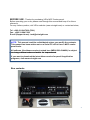
MCP combo panel
USER MANUAL (MEA2 520-5JAN09)
(MEA2.520-5JAN09)
Please read this manual before operating your units and keep it for future reference.
VRinsight
Virtual Reality Insight
Virtual Reality Insight
All stated here is subject to change without advanced notice for improvement.
Tel : +82-31-284-7090~91 Fax : +82-31-284-7092 E-mail : [email protected] Web site : www.vrinsight.com
1
BEFORE USE : Thanks for purchasing VRi’s MCP Combo panel.
Before operating your units, please read through this manual and keep it for future
reference.
For any further question, visit VRi’s web-site (www.vrinsight.com) or contact as below;
Tel : +082-31-284-7090 (7091)
Fax : +082-31-284-7092
E-mail (Support team) : [email protected]
NOTE : This manual could be redistributed unless you modify the contents.
This manual has been written out on a Serial FP v2/Jet Liner’s MCP combo
panel basis.
All software (& software versions) stated here (MEA2.520-5JAN09) is subject
to change without advanced notice for improvement.
improvement
If you want to download the latest driver version for panel & application
programs, visit www.vrinsight.com
Box contents
2
VRinsight
MCP combo panel
The MCP combo panel of VRinsight features various types of aircrafts’ panel with
full control complement ; default aircrafts of MSFS, most freeware and commercial
add-on
add
on aircraft (Wilco’s
(Wilco s B737 Classic,
Classic PMDG
PMDG’s
s B737NG & 744,
744 Level-D’s
Level D s B767B767
300 and PSS’ A319,320,330,340). It is completely interfaced with MSFS9 and
MSFSX through add-on software *SerialFP2” which enables MCP combo panel to
perform full simulation with simple connection your computer through USB.
Package including universal power supply adaptor (DC 5V).
The MCP combo panel is comprised of EFIS, MCP & COM (Instrument Radio)
part to understand advanced flight
p
g controls for beginners
g
and less advanced users
starting flight simulation games at a first step.
Each control part; EFIS, MCP & COM has push buttons, rotary knobs, toggle
S/Ws and/or 2 line character type LCDs offers actual flight circumstance with full
control complement.
•SerialFP2 software supports all functions to MCP combo panel
• MCP combo panel consumes high power. To avoid malfunction , do not use many other
USB interfacing devices. We recommend using external power supply (DC 5V adaptor)
• If you want to use a USB hub, be sure that the USB hub must compliant with USB 2.0
standard. Otherwise it may cause a malfunction.
3
EFIS part
MCP part
COM part
The MCP combo panel features the following controls:
EFIS part :
- Toggle S/Ws for VOR1,2/ADF1,2 .
- Knob S/Ws for MINS, BARO, CTR ; ND mode selector and TFC.
- Push buttons for FPV, MTR, WXR, NAVAID, WPT, ARPT, DATA
- All buttons and rotary knobs are user-programmable
MCP part :
- 2 line character type LCD displaying SPD, HDG, ALT and Pitch & Bank
at Autopilot
p
Status
- On/Off toggle S/Ws for F/D, A/T
- Thrust mode selection buttons: N1, SPD, FLCH
- Push buttons for HDG SEL & HOLD, ALT HOLD, V/S SEL, TOGA, CRZ,
VNAV, LNAV, CMDA, CMDB, CMDC, LOC, CWSA(Y/D), CWSB(BCRS),
APP
- On/Off toggle switch for DISENGAGE.
COM(Instrument Radio) and 8-User programmable control part :
- 2 line character type LCD displaying COM & NAVAID Frequencies,
DME distance, speed, VOR ID & CRS, Squawk code
- 5 push buttons for Instrument radio function selector
(COM, NAV, ADF, DME, TRANSPONDER)
- Rotary knob for NAVAID’s frequency change, CRS/OBS, Squawk Code
- TFR button for activating stand-by frequency
- 8 User programmable control buttons
4
Features
• Integrated unit with full radio stack function : EFIS part, MCP part, COM
part
• All necessary buttons, switches and LCD panel to input SPD, VOR, HDG
and all other functions for getting close to real flight.
• Offer actual flight circumstance via MCP combo panel with full control
complement
• Full metal cases
• One year warranty
Technical specifications
• USB interface type to computer
• External power requirement : DC 5V adaptor or USB power supply type to
MCP combo panel. We recommend using DC 5V adaptor.
• 50cm(W) x 14cm(H)
• 4Kg
Compatibility software
• Flight simulator 2004 / FSX by Microsoft
Operating software
• SerialFP2
5
SerialFP2 Installation
With MCP combo
b panel,
l an “I
“Install
t ll DVD” iis iincluded.
l d d Wh
When you iinsertt it iin DVD d
driver
i
of your computer, “VRinsight HTML” document will be shown. Then click “SerialFP2”
(operating software) and install it at a proper folder.
“SerialFP2” is the main operating software of VRinsight used for all VRinsight flight
panels.
SerialFP2 software supports full functions of MCP combo panel and completely
interfaced with MSFS9 and MSFSX enables full simulation with simple connection with
your computer through USB.
Be sure that when installing SerialFP2, “Install USB-Serial Driver” must be
checked.
After installation, you can find “SeiralFP2” in “All programs” of “Start menu”.
USB Connection
The connection between MCP combo panel and your computer is made using a USB
cable that plugs into an USB port on your computer. If you want to use a USB hub,
be sure that the USB hub must compliant with USB 2.0 standard. Otherwise it
may cause a malfunction.
When you connect MCP combo panel to your computer at first, your computer will
detect it and will describe the process step by step.
Power Connection
Power supplying of MCP combo panel is done by universal power supply adaptor DC
5V (Included in package) and/or USB port of your computer. Make sure that before
trying to operate MCP combo panel, you must confirm the USB connection first in
order to prevent malfunction.
Before trying to operate, be sure that LCD displaying is shown.
Run “SerialFP2”
When you confirm all setup processes done; “SerialFP2” installation, “USB connection”
and
d “P
“Power connection”,
ti ” you are ready
d tto operate
t MCP combo
b panel.l
Download & install “FSUIPC”
Refer to “Download & install FSUIPC” at “Download” part of www.vrinsight.com
6
Double click shortcut of “SerialFP2” or find it in “All programs” of “Start menu .
If e
everything
e yt g is
s do
done
ep
properly,
ope y, be
below
o window
do will be sshown.
o
Run MSFS9 / MSFSX and run SerialFP2. Drop down “Select Aircraft” to select aircrafts
and press “Load FS Module” button.
* Before operate MCP combo panel, check “Re-Try”.
7
EFIS part controls explanation
EFIS (Electronic Flight Instrument System) : It is used to control the respective
Primary Flight Display (PFD) and Navigation Display (ND). EFIS panel includes
controls for selecting various modes and ranges on the ND as well as switches to
display NAVAIDS, waypoint, airports and etc. Two toggle S/Ws allow displaying of
the left and right VOR and ADF bearing pointer on the ND. Controls are available to
set barometric altimeter settings for displaying on the PFD.
•The functions of each button and knob can be differed from the explanation according to
the aircraft's
aircraft s implementation
implementation. Also,
Also buttons and knobs are user programmable for another
functionality.
8
L or R VOR / ADF switch : Select NAVAID between VOR or
ADF.
Toggle
S/W
MIN
S
Pushing : Resets or blanks PFD display
Rotating : Adjusts PFD radio or baro minimums altitude
BAR
O
Pushing : Displays preselected barometric setting
Rotating : Adjusts barometric reference
CTR
Pushing : Displays full compass rose for APP, VOR and
MAP modes. Subsequent pushing alternates between
expanded and centered displays
Rotating : Changes ND(Navigation Display) mode among
APP, VOR, MAP, PLN.
APP : Approach mode, displays ILS, localizer and glide
slop information in heading up format. Reference ILS
receiver ILS frequency or identification
receiver,
identification, course and DME
Rotate &
Push
VOR : VOR mode, displays VOR navigation information in
heading up format. Reference VOR receiver, VOR
frequency or identification, course and DME and
TO/FROM information
MAP : Map mode, displays FMC-generated route and
map information airplane position,
position heading and track in
tracking-up format. Displays waypoints, including the
active waypoint within the selected range. Also displays
VNAV deviation
PLN : Plan mode, displays a stationary true north-up route
depiction. Route may be reviewed selecting “STEP” at
using the CDU legs
TFC
Pushing : Displays TCAS information on the ND
Rotating : Selects the desired ND nautical miles range
scale
9
FPV
MTRS
Displays
p y flight
g p
path vectors on PFD
Displays PFD altitude meters indications
MAP buttons : Selects or removes ND information. More than
one displayed may be selected at a time
WXR
Displays weather radar information
STA
Displays high and low altitude navigation aids in the 10, 20 or
40 NM range and high altitude navigation aids only if range is
selected above 40 NM
WPT
Displays waypoints if range selector is set to 10, 20 or 40 NM
ARPT
Di l
Displays
airports
i
t iinformation
f
ti ; ID
ID, di
distance
t
and
d etc
t
DATA
Displays the FMC estimated time of arrival and altitude at
each waypoint
Push SW
POS
TERR
Displays ADIRU and both GPS positions and VOR raw data
radials extended from the nose of the airplane to the stations.
Displays the Enhanced Ground Proximity Warning System
terrain data on the ND. The data is mutually exclusive of
WXR data, so selecting one deselects the other.
priorities are :
Between WXR and TERR the p
•Terrain warning
• Predictive wind shear warning
• Terrain caution
• PWS caution
10
MCP part controls explanation
MCP (Mode Control Panel) : It provides control of the Autopilot
Autopilot, Flight Director,
Director
Altitude alert and Auto-throttle System. The MCP is used to select and activate
Autopilot Flight Director System, (AFDS) modes and establish altitudes, speeds and
climb/descent profiles.
11
A/T
Toggles
gg
Auto-Throttle Mode On/Off
F/D
Activates or Deactivate Flight Director(F/D)
The commands bar on the PFD annunciated when activated.
DISEN
GAGE
CRS
Controls autopilot engagement
Rotating : Decides the course (OBS) to NAVAID(VOR)
SPD
Rotating : Decides the speed of airplane to fly
HDG
Rotating : Decides the heading of airplane to fly
ALT
Rotating : Decides the altitude of airplane to fly
V/S
Rotating : Decides the vertical speed of airplane to fly
12
TOGA
CRZ
N1
SPD
In takeoff / go-around / Cruise : Generates certain
t
torque
with
ith A/T is
i On.
O
FLCH
Changes the flight level to the altitude indicated on LCD
p y on PFD p
pitch flight
g mode annunciator as p
pitch
Displayed
mode and auto-throttle automatically engaged.
HDG
SEL
HDG
HLD
Autopilot heading mode: Heading Select(HDG
SEL), Heading Hold (HDG HLD)
HDG SEL sets heading on LCD, PFD and ND
HDG HLD holds heading established at wings level.
ALT
HLD
Engages Altitude as a pitch mode and displays it PFD pitch
flight mode annuniciator. AFDS commands pitch to maintain
Altitude
VNAV
Takes over and controls the pitch and airspeed in accordance
with
ith a pre-sett profile(If
fil (If VNAV and
d Auto-throttle
A t th ttl armed).
d) VNAV
engages above 400 feet radio altitude
LVNA
CMDA
LOC
Makes airplane tracking Magenta line on the ND. LNAV
engages if airplane is above 50 feet radio altitude, within 2.5
NM of active leg, and within path capture parameters of ground,
intercept angle and bank angle, to active leg.
CMDB
CMDC
Engages A/P (A,
E
(A B,
B C is
i th
the number
b off
/AP and is different on the type of airplane)
Engages Localizer and AFDS as roll mode to capture and
track inbound on front course
13
V/S
FPA
APP
Y/D
BCRS
Engages
g g vertical speed
p
or flight
g p
path angle
g as p
pitch mode
Engages Localizer as roll mode and glide slop as pitch mode
AFDS captures and tracks localizer in LOC mode and capture
glide slop in glide slop mode. Localizer captures when
intercept track angle is within 120 degrees of localizer course.
Glide slop captures when intercept track angle is within 80
degrees of localizer course.
Yaw Damper
Back-Course Mode
LCD display : It shows SPD, HDG, ALT, V/S and Autopilot Status
or Aircrafts attitude (Pitch & Bank)
14
COM part controls explanation
COM (Instrument Radio) Panel & 8-User Programmable Buttons :
It provides
id radios
di stack
t k ffunction
ti and
d user programmable
bl control
t lb
buttons.
tt
15
Selection buttons : Buttons are used to carry out a pre-defined
f
function
ti that
th t has
h been
b
assigned
i
d tto it b
by th
the currentt menu
GEAR
UP
GEAR
OFF
GEAR
DN
FLAP
UP
FLAP
DN
A.BRK
RTO
A.BRK
DEC
A.BRK
INC
8 User programmable control buttons according to the aircraft. Above
definitions are the example when it’s used with Level-D 767-300ER.
COM
NAV
ADF
DME
TRN
Select one of 5 Radio Panel functions.
Swap COM/NAV’s standby to Active frequency
AUX
AUX button.
Rotate to select COM/NAV/ADF frequency,
frequency Squawk
Pushes to change the digit
LCD display : It shows the information of COM1 &2, NAV1 & 2,
ADF, DME, TRNANSPONDER(SQUAWK CODE)
Converts power source
USB : Supplied the power from USB port
Neutral : Power off
EXT : Supplied the power from external power supplier (DC
5V adaptor)
16
Preparing MCP combo panel before flight
Check installation “SerialFP2”.
Step 1 : Initial check up
As USB cable is plugged into your computer, initial messages are displayed on LCD
screen. MCP combo panel has 2-line character type LCD to display various flight data
and control information.
NOTE : Please check the Serial No & Version.
All software(& software version) stated here are subject to change without
advanced notice for improvement.
Please verify the latest version for panel via www.vrinsight.com
Initial message of MCP part
Initial message of COM part
Initial message of MCP combo panel
panel, firmware version is showed up
up.
LCD blinking is normal. LCD is blinking from time to time until the panel is linked to
application software and flight simulator.
17
Step 2 : Run flight simulator (MSFS9 / MSFSX)
1) Run flight simulator (MSFS9 / MSFSX) before linking USB connected panel to
application software “SerialFP2”.
2) Select flight.
Step 3 : Run panel linking application software “SerialFP2”.
Run application software “SerialFP2” which linking MCP combo panel to flight simulator.
Be sure that flight simulator is already started.
When you run “SerialFP2”, below window will be shown.
1
2
3
4
5
7
6
8
1 : Number of COM(USB) port
2 : Type of panel
3 : Fi
Firm ware version
i
4 : Aircraft selection
5 : Link to game
6 : Software loading sequence change
Original sequence
(MSFS loading first => SerialFP2 running)
New sequence
(MSFS loading / SerialFP2 running first
=> SerialFP2 running / MSFS loading)
7 : Input test for panel
8 : Link test for panel with game
18
Drop down “Select Aircraft” and press “Load FS Module”.
As connection success, LCD display will be also changed as follows.
After connection message of MCP part
After connection message of COM part
Above pictures showing the display on MCP combo panel after successful linking.
Basically It displays SPD, HDG, ALT and aircraft’s attitude; bank and pitch on upper
and lower line of “----“.
MCP combo panel supports various aircrafts (MSFS’s original aircrafts and other
payware aircrafts such as Wilco,
Wilco PMDG,
PMDG Level-D & PSS)
PSS). All of buttons on the panel
are user programmable. Use key-mapping software provided;
“SPF2_MCP_KeyMapper” for MCP-Combo panel. After an aircraft selected, press
“Load FS Module” button.
19
Key-command sticker
key-command sticker is provided with product and enclosed DVD has
“KeyCap_Decal.pdf” file for “LETTERING” based on MSFS9 / MSFSX . Please print it
out and use for your purpose.
Payware aircrafts.
MCP combo panel supports various type of aircrafts including default aircraft of MSFS,
freeware and payware.
payware Supported payware aircrafts are;
MSFS Original Aircraft
Level-D B763-SP3(FS9) Level-D B763-SP2a(FSX)
PMDG-B737/747(FS9) PMDG-B737 Only(FS9) PMDG-B737/747-FS2Crew(FS9)
PMDG-B744(FSX)
Wilco B737 PIC Wilco 777ER Wilco airbus ½ (2D) Wilco airbus ½ (3D) Wilco A380 v2
Wilco embraer-ERJ Wilco embraer-Legacy Wilco Cessna Citation X
PSS A319/320(FS9) PSS A330/340(FS9)
Cooksky Super 80 pro
F1 ATR-72
All of controls on the panel, push buttons and rotary encoders, are programmable using
key-mapping software. Any aircrafts can be supported, if key-commands are known at least
and added on “SerialFP2” software’s aircraft list.
PMDG-737NG/744
PMDG controls aircrafts using key-commands. Many controls are missing in pre-defined
key-commands. Fully defined command files are provided in enclosed DVD. Apply
These files before flight with PMDG’s 737NG and 744 aircraft. To work correctly with
provided definition file and the MCP combo panel, service pack and update patch must
be applied; SP1 and update patch 1.3 for PMDG-737NG and update 1.x for PMDG-744.
Installing Key-Command Definition file
((1)) PMDG’s key-command
y
files are exist at …\Flight
g Simulator 9\PMDG.
It’s 737Kbd.ini for PMDG-737NG and 747400Kbd.ini for PMDG-744.
Replace these files with provided.
(2) If only PMDG-737NG aircraft is installed,
Find key-command definition file named “737Kbd.ini” at \Aircraft support\PMDG_
B737NG_747400\Installed_737_only\ and copy to …\Flight Simulator 9\PMDG\.
20
(3) If PMDG-737NG/744 are installed,
Find two key-command definition file named “737Kbd.ini” and “747400Kbd.ini” at
\
\Aircraft
f support\PMDG_B737NG_747400\
\
G
G
\ and copy to …\Flight
\
S
Simulator
9
\PMDG\.
(4) Confirm key-commands are loaded correctly. Follow MSFS menu, PMDG ->
General->Keyboard Commands and examine the definitions.
Be sure that all commands are defined to Key Combination without blank.
Find matched panel drawing with newly defined key-commands at \Doc\SerialFP2_
MCP_Setting_PMDG.pdf. Now you are ready to fly PMDG’s aircraft with MCP combo
panel.
MCP combo panel application to PMDG’s
(1) Confirm “FSUIPC” and KeyMapper files are installed before running MSFS9.
(2) Follow MCP combo panel running procedure (Panel checking Æ Running MSFS9 Æ
Running SerialFP2)
(3) Default key-map definitions for PMDG are below.
21
Push to MTR
2 . DEC Altimeter
3 . ALT STD
1 . INC Altimeter
Push to FPS
...
1 .UP to F / D On
2 /ADF 2
2 DEC
STA
WPT
CTR
FPS
ARPT DATA
TFC
MTR
JetLiner
POS TERR
ADF 2
VOR 2
BARO
’ s MCP
2/
F/ D
F
A/ T
TOGA
T
1
CRS
SPD
FLCH
MCP
Push to
...
SEL
HDG
- LCD
D
HLD
((FL )
3 . Push to
(FL )
2 . DEC Altitude
HLD
ALT
VNAV
APP
LOC
LNAV
Push to A
/P C
CWSB
CWSB
CMDB
COM
NAV
TRANSPONDER
ADF
RADIO
O
DME 1/ 2 Select
ADF 1 / 2 Select
NAV 1/ 2 Select
COM 1/ 2 Select
DISENGAGE
CMDC
Push to CMDB
...
/ P CMDA
Push to
Push to A
/ P APP On / Off
/ P LOC On / Off
Push to A
Push to A
A /P ENGAGE
CWS
SA
CMD
DA
1 . Up to A / P Engage
2 . Down to A / P Disengage
/P CWSA
FPA
V/ S
Push to A
2 DEC
.
V . Speed (x 100 )
3 . Push to
AV
.NA
Panel
Push too L . NAV
Push to V
737 / 744
1 . INC V . Speed (x100 )
1 .INC Altitude
Push to ALT HOLD
Push to HDG HOLD
Push to HDG SEL
N1
SPD
2 .DEC Heading
3 . Push to
(>100 )
( <999 )
Push to THR FLCH
Push too THR SPD
Push to THR N
3 . Push to
1 . INC Course / OBS
2 . DEC Course / OBS
3 . Push to
1 .INC Speed
2 . DEC Speed
: PMDG
G
1 . INC Heading
Type
DME
- LCD
TRN
< - X ->
MODE
Pussh to TFR
Pow
wer Src
. Select ( USB / Off/ Ext )
5 . TRN : SB 3 Mode - C ( NORM / STBY )
4 . DME :
3 . ADF :
1 . COM :
2 . NAV :
Push to Radio View
Push to THR View
Push to OH View
Push to FMC View
Push to LOC View
Push to APP View
Push to Zoom View
Push to Mail View
* To ru
un SerialFP v2/MCP
P properly at PMDG
G 737NG, set up 60
00/700/800/900 files and update patch
hes.
KeyM
Mapper re-definitio
on can be done using SPF2_MCP_KeyMapper.exe.
Push to TERR
Push to POS
Pussh to DATA
Push to APR
RT
Push to WPT
WX
W
ADF 1
VOR 1
MINS
...
SerialFP v
...
Push to
Push to
P to A / T Engage
1 .UP
2 . Down to A / T Disengage
2 . Down too F / D Off
(BARO )
(BARO )
Push to STA
Push to WX
1 . Up to INC VOR
2 . Down to VOR
2 . CCR to DEC ND range
3 . Push to ND TFC
1 . CR to INC ND range
3 . Push to ND CTR
1 . CR to INC ND mode
2 . CCR to DEC ND mode
1 . Up to INC VOR
1/ ADF 1
2 . Down to DEC VOR
1/ ADF 1
3 . Push to
1 . INC MINS
2 . DEC MINS
22
Level-D 767-300ER
Level-D provides SDK
S
(S f
(Software
Development Kit)) for
f 767-300ER aircrafts.
f External
add-on software or hardware can access Level-D’s controls directly instead of keycommand. This SDK is great for developers. Interfacing DLL module which is
developed with Level-D’s SDK is provided for MCP combo panel. The DLL module
is developed with SP3 of Level-D 767-300ER. Be sure this patch, SP3 is applied.
Find matched panel drawing with interfacing module at
\Doc\SerialFP2_MCP_Setting_LVLD_763.pdf.
N
Now
you are ready
d tto fl
fly L
Level-D’s
l D’ greatest
t t aircraft
i
ft with
ith MCP combo
b panel.l
MCP combo panel application to Level-D’s
(1) All service packs (SP3) must be installed before running MSFS9 2004.
(2) Follow MCP combo panel running procedure (Panel checkingÆ Running MSFS9
2004 Æ Running SerialFP2).
(3) Enjoy your flight
flight. Basic functions of panel are below
below.
23
Push to
(BARO )
(LEFT ) to VOR
(LEFT ) to ADF
...
_ DH
_DH
...
( Right ) to VOR
( Right ) to ADF
FPS
...
...
TFC
MTR
JetLiner
POS
TERR
ADF 2
VOR 2
BARO
1
CRS
Push to THR FLCH
Push tto THR SPD
Push to TH
HR N
F/D
F
A /T
TOGA
...
Push to
N1
...
FLCH
Push to ALT HOLD
SEL
HDG
HLD
ALT
Push to VS Button
HLD
( FL )
(FL )
Y/ D On / Off
APP
LOC
LNAV
/ P LOC On
A / P Left
COM
TRANSPONDER
ADF
RADIIO
NAV
DME 1/ 2 Select
ADF 1/ 2 Select
ILS & VOR / DME (L / R )
COM 1/ 2 Select
B /C On / Off
DISENGAGE
CWSB
A/ P Right
A /P Center
/ Off
/ Off
Push to A / P APP On
Push to A
Panel
A / P ENGAGE
CMDC
CMDB
CW
WSA
CM
MDA
2. Down to A / P Disengage
1. Up to A / P Engage
FPA
V/ S
VNAV
.NAV
Push tto L . NAV
Push to V
- D 767 - 30
00
1 . Increase V . Speed (x100 )
2 . Decrease V . Speed
3 . Push to ...
MCP - LCD
D
3. Push to
1. Increase Altitudee
2. Decrease Altitude
Push to HDG HOLD
...
SPD
SPD
2 . Decrease Heading
3 . Push to HDLSEL
1 . Increase Heading
: LEVEL
DME
- LCD
TRN
< -X ->
MODE
*K
KeyMapper re-de
efinition can be d
done using \bin\SPF2_MCP_Key
yMapper.exe.
Capt / FO Panel Swap
2/
3 . Push ...
1 OBS
1 OBS
3 . Push to
1 . Increase AP SPD
2 . Decrease AP SPD
Ty
ype
1 . Increase NAV
2 . Decrease NAV
V
’ s MCP
SerialFP v
Push to
Push to
WPT ARPT DATA
CTR
GA Switch
EHIS RTE DATA
STA
ADF 1
VOR 1
MINS
WX
W
EHIS APRT
EHIS WPT
EHIS NAVAID
EHIS INOP
1 . RMI knob
2 . RMI knob
2 . Decrease ND Range
3 . Push ND Range Button
1 . Increase ND Range
3 . Push ...
2 . Decrease ND Mode
1 . Increase ND Mode
1 . RMI knob
2 . RMI knob
3 . Push to
(BARO )
1 . INC Altimeter
...
1 . A / T Arm ( Up )
2 . A / T Disarm (Down )
1 . F/ D Onn (Up )
2 . F/D Offf (Down )
2 . DEC Altimeter
3 . ALT STD
Push to
1 . Increase ADI
2 . Decrease ADI
24
...
...
Puush to TFR
Poower Src
...
...
...
...
...
. Select
(USB / Off / Ext )
5 . TRN : SB 3 Mode - C (NORM / STBY )
3 . ADF :
4 . DME :
1 . COM :
2 . NAV :
...
Push to
Push to
Push to
Push to
Push to
Push to
Push to
Puush to
3-3. PSS-A330
PSS’s A330 aircraft is controlled by key-command similar to PMDG’s. Defect to PSS’s
aircraft command definition is “fast rotation”,i.e. SPD, HDG, ALT etc, are missing.
Response to incoming command from the panel is very slow. Newly defined keycommand file is provided and find matched panel drawing at
\Doc\ SerialFP2_MCP_Setting_PSS_A330.pdf.
PSS A-330 aircraft’s configuration file where key-commands are defined exists at
…\Flight Simulator 9\Pss\Airbus A3XX\. Copy provided new configuration file Aircraft
support\PSS_A3XX\
t\PSS A3XX\ config330.pnl
fi 330 l to
t …\Flight
\Fli ht Si
Simulator
l t 9\P
9\Pss\Airbus
\Ai b A3XX\
A3XX\.
Now you are ready to fly PSS A-330 aircraft with MCP combo panel.
25
4. Radio panel
MCP combo panel is incorporated with MCP, EFIS and radio panel. Radio panel used
for all aircrafts features frequency input (COM / NAV / ADF), information display (VOR
/ DME) and Squawk code input to Transponder.
After converting DME screen, input OBS1, OBS2 value with rotary switch.
- COM1,COM2 : Inputs
p
ATC and communication frequency.
q
y
- NAV1, NAV2 : Inputs frequency of radio navigation facility (VOR, ILS/DME).
- ADF : Inputs ADF frequency.
- DME : Displays frequency information of radio navigation facility (VOR,ILS/DME)
inputted by NAV1, NAV2. Also displays ID, distance & deviant speed (from
radio navigation facility) and approaching speed (to radio navigation facility).
- TRN : Inputs Squawk code.
Radio panel has selection buttons (COM/NAV/ADF/DME/TRN).
TFR button for activating stand-by frequency. Rotary-key for changing digit.
26
MODE
RADIO-LCD
RADIO
LCD
<-X->
COM
NAV
ADF
DME
1. COM:
2. NAV:
3. ADF:
4. DME:
5. TRN: SB3 Mode-C (NORM/STBY)
TRN
Power Src. Select (USB/Off/Ext)
Push to TFR
COM1/2 Select
ILS & VOR/DME(L/R)
ADF 1/2 Select
DME 1/2 Select
TRANSPONDER
As pushing each function button, LCD displays various information
Rotating rotary switch changes stand-by frequency (or squawk code).
Pushing rotary switch changes a digit. TFR switch(< - X - >) activates current stand-by
frequency (or squawk code). DME just displays information of radio navigation facility
tuned to navigation.
With SquawkBox3 of VATSIM, TRNsponder offers “MODE-C NORM/STBY” conversion
function.
Power source select switch :
Convert switch when you change power source
27
Trouble shooting
O /O
ON/OFF
trouble - USB
S port and power supply.
MCP combo panel is high power consuming device. Connect the panel to USB port on
your computer directly. When it works incorrectly, using external power supplying AC-toDC adaptor is recommended.
Adaptor 5V, 1A
If DC power adaptor is used, be sure power switch position to EXT.
INITIAL LCD DISPLAY trouble - Link test.
After connection, check the initial messages (MCP & COM part). If no message shown,
confirm whether you have checked “Install USB Serial Driver” of “SerialFP2” setup
wizard. If SerailFP2 can not find COM port for CDU, check Device Manager whether
CDU has been assigned or not.
Aft checking,
After
h ki
lilinkage
k
still
till d
does nott work.
k Th
Then use other
th USB ports.
t S
Some USB portt
is dummy port.
Initial LCD display
MCP part
COM part
28
LCD BRIGHTNESS trouble - LCD contrast
When the panel is plug into your computer, initial messages are displayed on LCD
after power-on selftest. If it’s dimmed or cloudy, tune the contrast.
Tune LCD brightness
dark
bright
PANEL FUNCTION trouble 1 - Panel function test
When MCP combo panel is linked to “SerialFP2” software correctly, control linkage
and functioning of the panel can be tested without starting flight simulator.
(1) Check the check box.
(2) P
Press b
buttons
tt
or rotate
t t rotaryt
encoder of your MCP combo panel.
Commands are transferred to your
computer and result will be displayed
on software.
Some transferred values, i.e. SPD,
HDG, and ALT, are identical to
displayed on LCD
LCD.
29
PANEL FUNCTION trouble 2- FSUIPC check
Download & install FSUIPC is required for MCP combo panel use with Microsoft’s
Flight Simulator. If you didn’t download & install, do it now. Basic function of FSUIPC is
enough to operate. No registration is required.
Also check “FSUIPC.dll” file is in “\Program Files\Microsoft Games\Flight Simulator9
\Modules”. Further information, see “download & install FSUIPC” part.
PANEL FUNCTION trouble 3 – Procedure check
1) Run MSFS first
2) Download & install FSUIPC
3) Setup “SerialFP2”
4) Connect MCP panel to PC
5) Run “SerialFP2”
6) Check “Re-Try” is checked
7) Select your aircraft
30