1
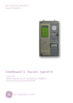
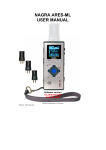
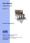
RAIL MOUNTED NETWORK METER TYPE N27P USER’S MANUAL 1 Contents 1. APPLICATION................................................................................... 5 2. METER SET...................................................................................... 6 3. BASIC REQUIREMENTS, SAFETY OF USE................................... 7 4. INSTALLATION................................................................................. 8 4.1 Mounting method...................................................................... 8 4.2 Connections............................................................................. 10 5. OPERATION....................................................................................11 5.1 Description of front panel........................................................11 5.2 Messages after switching the power supply on....................11 6. MENU.............................................................................................. 12 6.1 Display...................................................................................... 12 6.2 Menu structure......................................................................... 15 6.3 Programming the inputs......................................................... 18 6.4 Reseting counters................................................................... 20 6.5 Display settings....................................................................... 21 6.6 Programming the alarms........................................................ 22 6.7 Programming the outputs....................................................... 29 6.8 Service settings....................................................................... 31 7. SERIAL INTERFACES.................................................................... 33 7.1 RS485 – list of parameters...................................................... 33 7.2 USB – list of parameters......................................................... 34 7.3 Map of N27P meter registers.................................................. 34 8. ERROR CODES.............................................................................. 49 9. FIRMWARE UPDATING................................................................. 50 9.1 Software L1 level update........................................................ 50 9.2 Software L2 level update........................................................ 53 10. TECHICAL SPECIFICATION........................................................ 54 11. ordering CODE........................................................................ 59 1. APPLICATION The N27P is a programmable digital device used to measure the parameters of single-phase electrical networks. The meter measures and calculates the following values: phase voltage • 10 minutes’ mean voltage • • current active power • reactive power • apparent power • active power factor • ratio of reactive/active power • mean active power • phase shift • input of active energy • output of active energy • input of reactive energy • output of reactive energy • apparent energy • • frequency 10 seconds’ mean frequency • • time maximum and minimum values of: • - phase-to-neutral voltage; - current; - active power; - reactive power; - apparent power; - active power factor; - tangent φ; - frequency; - average active power; Itispossibletoentertransformerratioofusedexternalcurrent orvoltagetransformerswhichwillbeaccountedforinthemeasurementandcalculationofallvalues.AllvaluesandconfigurationparametersareaccessiblethroughtheRS485andUSB interfaces.The meter output signals are galvanically isolated fromtheinputandpowersupplysignals. Figure 1. Meter for direct measurements (left) Meter for indirect measurements (right) 2. METER SET Themetersetcomprises: N27Pmeter............................. 1pc UserManual............................ 1pc WarrantyCard......................... 1pc CD........................................... 1pc Accessories: ThefollowingaccessoriescanbeorderedfortheN27Pmeter: -USBA/miniUSBcable–1m,black;ordercode:1126-271-028 6 3. BASIC REQUIREMENTS, SAFETY OF USE The symbols used in the manual have the following meaning: Warning! Potentially hazardous situations. Read before connecting the device! Failure to observe recommendations marked with this symbol can result in heavy personal injuries and device damage Caution! Generally useful notes. Read them to make the device use easier. Pay attention to these notes when the device is not working correctly. Possible consequences if the information is disregarded! In terms of safety of use the meter conforms to EN 61010-1. Safety notes: • Electrical connections should be made by a person with required licences to install electrical devices. • Check the correctness of connections before turning the meter on. • Removal of the meter cover during the warranty period makes the warranty null and void. • • The meter is intended for installation and use in industrial electromagnetic environments. The building electrical installation should have a switch or a circuit breaker located near the device, easily accessible and properly marked. 4. INSTALLATION 4.1. Mounting method The N27P meter can be installed in modular distribution boards on the 35 mm rail bracket. The meter enclosure is made of plastic and its dimensions are 53 x 110 x 60.5 mm. On the outside of the meter there are screw terminal blocks to connect the measurement signals using the leads up to 5.3 mm2 in cross section (1 A / 5 A), and up to 16 mm2 (32 A / 63 A) and the remaining signals using the leads up to 2.5 mm2. The meter dimensions are shown in Figure 2. Figure 2. Meter dimensions The meters shall not be installed on the rail in direct contact with other heat emitting devices (e.g. successive N27P meters). Leave the minimum 5-mm space between devices to enable radiation of heat from the enclosure to the ambient air. Otherwise, the temperature in direct vicinity of the meter may exceed the rated operating temperature. 4.2 Connections The meter connections are shown in Figure 3. Range 32 A / 63 A 63 A 1 2 3 4 5 6 a b A B Range 1 A / 5 A Figure 3. N27P wiring diagrams 10 5. OPERATION 5.1 Description of front panel Display USB interface Control buttons Figure 4. Front panel 5.2 Messages after switching the power supply on After switching the power on, the meter shows information about manufacturer, software version and device serial number. Then the meter goes to display the measured values. 11 6. menu 6.1 Display Upper displayed value Alarm indicators USB connection indicator Data transmission indicators R - receiving T - transmitting Energy character: Main displayed value. Selection with use of button „▲”. capacitive inductive consumed produced Additional displayed value. Selection with use of button „▼”. Figure 5. N27P meter display 12 The main displayed value is selected using the UP button in the following sequence: Current Active power Voltage Reactive power Frequency Apparent power Tangent j Power Factor Figure 6. Selecting main displayed value 13 The additional displayed value is selected using the DOWN button in the following sequence: Produced active energy Inductive reactive energy Consumed active energy Capacitive reactive energy Bargraph Apparent energy Figure 7. Selecting additional displayed value The upper displayed value is selected from the meter menu (DISPLAY→UP DISPLAY). 14 6.2 Menu structure The N27P parameters may be modified from the display menu level. and hold it for about 3 seconds. Use the UP and DOWN buttons ( ) and hold it for about 3 seconds. Use the UP and DOWN buttons ( , ), to navigate the menu. To accept choice press ENTER, to cancel or exit press the UP and DOWN buttons simultaneously or wait 15 seconds. Another way to go level up is to select the last position on every submenu (-----). The menu structure is shown in table 1. Note: You can protect the editing of parameters from the display menu with a password. In such case, it is possible only to view the meter settings and not to modify them. To set or change the password use the SERVICE→PASSWORD menu option. If you forgot the password carry out the following procedure to remove it: 1. Turn the meter power off 2. Press simultaneously and hold the UP and DOWN buttons ( , ), 3. Turn the meter power on 4. Wait for about 5 seconds and release the buttons 15 Table 1 INPUT Parameters of input VOLTAGE RANGE CURRENT RANGE VOLTAGE RATIO CURRENT RATIO INPUT SYNCH Voltage range of votalge input Current range of current input Voltage transformer ratio Current transformer ratio Input synchronizing method clr avg power CLEAR clr en count Counters reseting Reseting energy counters DISPLAY upper display bargraph par. bargraph sym. bargraph% Display settings Selection of value displayed on upper line of display Selection of input parameter for bargraph Selection of bargraph style Percent of input parameters as 100% of bargraph ALARM 1 Input value output type low level in high level in delay on Alarm 1 setting Selection of input signal Selection of output type Low level of input signal High level of input signal Delay for alarm 1 turning on ALARM 2 Input value output type low level in high level in delay on Alarm 2 setting Selection of input signal Selection of output type Low level of input signal High level of input signal Delay for alarm 2 turning on OUTPUT Input value output type low level in high level in low lev out Output settings Selection of input signal Selection of output type Low level of input signal High level of input signal Low level of output signal SERVICE default param password time date language Service settings Restore factory settings Menu lock password Time settins Date settings Selection of menu language 16 Reseting average power counter clr 10 min v CRL min-max CRL time cnt Reseting 10-minutes and maximal values counters Reseting minimal and maximal values counters Reseting turningon counter react pw mode react en mode Pw avg synch demand power Reactive power calculation method Reactive energy calculation method Avarage power synchronization method Ordered power delay off lock turn on signal maint Delay for alarm 1 turning off Restart interlock Maintenance of alarm indication delay off lock turn on signal maint Delay for alarm 2 turning off Restart interlock Maintenance of alarm indication high lev out Output mode error value address mode baudrate High level of output signal Output mode Output signal level on error Device address Transmission mode Transmission speed 17 6.3 Programming the inputs The inputs can be programmed from the INPUTS menu according to table 2. Table 2 INPUTS Parameter Parameter symbol Range Remarks/Description Factory value 1 Voltage range VOLTAGE RANGE 100 V, 400 V Selection of input voltage range 400 V 2 Current range CURRENT RANGE 1 A, 5 A (32 A, 63 A)* Selection of input current range 5 A (63 A)* 3 Voltage transformer ratio VOLTAGE RATIO 0,1...4 000,0 1,0 4 Current transformer ratio CURRENT RATIO 1...10 000 1 Input synchronization INPUT SYNCH WITH VOLTAGE WITH CURRENT WITH VOLTAGE (all parametrs are measured) WITH CURRENT (current and frequency only) Reactive power calculation method REACT PW MODE TRIANGLE SINUS-HARMON. TRIANGLE Lp. 5 Q= √S −P 2 2 WITH VOLTAGE TRIANGLE SINUS-HARMON. k 6 Q=∑ U i⋅I i⋅sin (∢U i , I i ) i =1 k – HARMONIC NUMBER (21 FOR 50 Hz, 18 FOR 60 Hz) 7 18 Reactive energy calculation method REACT EN MODE CAPAC-INDUC POSIT-NEGATIVE CAPAC-IINDUC – capacitiv or inductive energy POSIT-NEGATIVE – positive or negative energy CAPACIINDUC Synchronization of average active power PW AVG SYNCH MOVING WINDOW CLK 15 MIN CLK 30 MIN CLK 60 MIN Average active power synchronization: MOVING WINDOW – 15-minutes moving window CLK 15 MIN – measuring synchronized with clock every 15-minutes CLK 30 MIN - measuring synchronized with clock every 30-minutes CLK 60 MIN - measuring synchronized with clock every 60-minutes, MOVING WINDOW Demand power DEMAND POWER -144.0 %...144.0 [%] Demand power to predict power consumption in percent of nominal value 100,0 [%] 8 9 *) - meter for direct measurements 19 6.4 Reseting counters Reseting counters can be done from the CLEAR menu according to table 3. Table 3 CLEAR Lp. Parameter Parameter symbol Range Remarks/Description Factory value Reseting active energy, reactive energy, apparent energy counters, or all of them. NO 1 Reseting energy counters CLR EN COUNT NO ACTIVE REACTIVE APPARENT ALL 2 Reseting average power counters CLR 10 MIN V NO YES NO 3 Reseting 10-minutes average voltage counter CLR MIN MAX NO YES NO 4 Reseting minimal and maximal value counters KASUJ MIN-MAX NO YES NO 5 Reseting powering on counter CLR TIME CNT NO YES NO 20 6.5 Display settings Additional display settings are available on DISPLAY position of menu, according to table 4. Table 4 DISPLAY Lp. Parameter Parameter symbol Range 1 Upper display value UPPER DISPLAY VOLTAGE CURRENT ACTIVE POWER POWER FACTOR TANGENT FREQUENCY CURRENT /3 2 Input signal for bargraph BARGRAPH PAR. table 6 3 Bargraph style BARGRAPH SYM. NO YES Remarks/Description Factory value Selection of parameter to display on upper line of display, see Figure 5. FREQUENCY (see table 6) VOLTAGE Selection of bargraph style. NO – displaying values changing in range from 0 to 120% of input signal YES – displaying values changing in range from -120% to +120% of input signal. If measured value is equal or greater than 120 % of nominal value then bargraph will display with pulsing value 120 %. NO 21 4 Bargraph range BARGRAPH % 0...120 [%] Settings a percentage value of input parameter as a nominal value of bargraph. For example, after selecting BARGRAPH PAR. as VOLTAGE and setting BARGRAPH % to 50.0 % at nominal voltage range as 400 V, you will get the 100 % bargraph reading at measured voltage equal 200 V. 100 [%] 6.6 Programming the alarms The alarms can be programmed from the ALARM 1/ALARM 2 menus according to table 5. Table 5 ALARM 1 / ALARM 2 Lp. 1 22 Parameter Input signal Parameter symbol INPUT VALUE Range table 6 Remarks/Description (see table 6) Factory value ACTIVE POWER Type of alarm output OUTPUT TYPE n-on n-off on off h-on h-off Setting the alarm type. The alarm types n-on, n-off, on and off are presented graphically in Figure 8. The h-on type turns the alarm on permanently, the h-off turns the alarm off permanently. Alarm 1 controls the first meter relay output. Alarm 2 controls the second meter relay output (in case of meter with two relay outputs) or only indicates the alarm occurrence on the display. n-on Low value of input signal LOW LEVEL IN -144,0... 144,0 [%] Low value of the meter-controlled parameter. In Figure 8 this value is marked as AL_L 99.0 [%] High value of input signal HIGH LEVEL IN -144,0... 144,0 [%] High value of the meter-controlled parameter. In Fgure 8 this value is marked as AL_H 101.0 [%] 5 Alarm turn-on delay DELAY ON 0...3600 [s] Alarm lay turn-on dein seconds. 0 [s] 6 Alarm turn-off delay DELAY OFF 0...3600 [s] Alarm lay turn-off dein seconds. 0 [s] Blocking next alarm activation LOCK TURN ON 0...3600 [s] The next activation of the alarm is blocked for the specified time in seconds. Before this time expires, the next alarm will be ignored. 0 [s] 2 3 4 7 23 Keeping the alarm signal indication SIGNAL MAINT NO YES Keeping the alarm signal. If this option is activated, when the alarm condition disappears, the display shows flashing alarm number. This option is particularly useful as a memory of short alarms. To cancel the alarm indication, press and hold simultaneously DOWN and 8 UP buttons ( for about 2 s. , NO ) a) n-on Alarm state on off Measured value 24 Alarm state Measured value b) n-off Alarm state Alarm state on on on off off Measured value Measured value e c) on Alarm state on off off e Measured value d) off Alarm state on on off Measured value Figure 8. Alarm types Alarm state 25 Selecting the output values: Item/ value in the 4024, 4032, 4040 register Displayed parameter 00 OFF Value type Table 6 Value for per cent calculations (100 %) No value /output off/ disabled 01 VOLTAGE Voltage Un [V] * 02 CURRENT Current In [A] * 03 ACTIVE PWR. 04 APPARENT PWR. Active power Reactive power Un x In x sin(90°) [Var] * 05 MOC POZORNA Apparent power Un x In [VA] * 06 POWER FACTOR Power factor PF 1 07 TANGENT 08 FREQUENCY 09 AVG ACTIVE PW Averaged active power 10 10MIN VOLTAGE Averaged 10-minute voltage Un [V] * 11 10SEC FREQ. Averaged 10-second frequency 100 [Hz] 12 CURRENT /3 One third of the current In [A] * 13 DEMAND POWER Demand power 3 x Un x In x cos(0°) [W] * 26 tangent Un x In x cos(0°) [W] * frequency 1 100 [Hz] 3 x Un x In x cos(0°) [W] * Alarm settings, example 1: Set alarm of n-on type for active power, nominal ranges: 5 A, 400 V. Alarm turning-on at 2100 W, turning-off below 1900 W. Calculating: nominal active power: P = 400 V x 5 A = 2000 W 2000 W – 100 % 2000 W – 100 % 2100 W – AL_H % 1900 W – AL_L % So: AL_H = 105.0 % AL_L = 95 % Set: INPUT VALUE: ACTIVE POWER, OUTPUT TYPE: n-on, LOW LEVEL IN: 95.5 %, HIGH LEVEL IN: 105 % Alarm settings, example 2: Set early warning of the possibility ordered power equal 1MW on the level with 15 minutes. Current transformer nominal voltage 400 V. Maximal momentary of exceeding 90 % settled 2500: 5 A, power 1.5 MW. Calculating: nominal active power of N27P meter: P = 400 V x 2500 A (500 x 5 A) = 1 MW (500 x 2000 W) – 100 %; 90.0 % of demand power / nominal power = 90.0 % x 1 MW / 1 MW = 90.0 % of nominal range; Ordered power (power to use): 1 Mwh / 4 quarters of the hour = 900 Mws, 90 % - 810 Mws, the remaining 10 % at maximal power consumption would be used in time: 900 MWs / 1.5 MW = 10 % x 900 MWs / 1.5 MW = 60 s. Figure 9 shows example of using demand power parameter to turn on the alarm. Delay is set to 0 seconds. In the example above for remaining 10 % of demand power at maximal power consumption, a device could operate 60 s without exposing the recipient to penalties. With alarm turn on delay set to 60 seconds, alarm would not be turned on. 27 Imported power Ordered power (energy) Time Relay enabled Relay disabled State of contacts Ordered power AL_H = 90.0 % AL_L = 89.9 % CTime of delay AL_dt_on = 0 sec Figure 9. Measurement of demand active power, synchronized with the clock for 15 minutes, with alarm set at 90 % of utilization Set: U INPUT VALUE: DEMAND POWER, OUTPUT TYPE: n-on, LOW LEVEL IN: 90.0 %, HIGH LEVEL IN: 89.9 %, CURRENT RATIO: 500, PW AVG SYNCH: MOVING WINDOW or CLK 15 MIN, DELAY ON: 0 s or 60 s. 28 6.7 Programming the outputs The outputs can be programmed in the OUTPUT menu according to table 7. Table 7 OUTPUT Factory value Item Parameter symbol Parameter 1 Input parameter of analogue output INPUT VALUE table 6 (code acc. to table 6) ACTIVE POWER 2 Type of analogue output OUTPUT TYPE 0..20 mA 4...20 mA The output range can be selected 0...20 mA 3 Low value of input parameter LOW LEVEL IN -144.0... 144.0 [%] Low value of input parameter (LV in fig. 9). Corresponds to LOW LEVEL in the analogue output. 0.0 [%] 4 High value of input parameter HIGH LEVEL IN -144.0... 144.0 [%] High value of input parameter (HV in fig. 9). Corresponds to HIGH LEVEL in the analogue output. 100.0 [%] 5 Low level of analogue output LOW LEV OUT 0,00... 22,00 [mA] Low signal on analogue output (LL in fig. 9). 0.00 [mA] 6 High level of analogue output HIGH LEV OUT 0,00... 22,00 [mA] High signal on analogue output (HL in fig. 9). 20.00 [mA] Range Remarks/Description 29 7 Manual settings MAN SETTING NORMAL REG. 4044 REG. 4045 Manual control of analogue output. The NORMAL option controls the output on the basis of the perfformacne specified by the values set in LOW VALUE, HIGH VALUE, LOWE LEVEL, HIGH LEVEL (fig. 9). In REG. 4044 or REG. 4045 options the analogue output is permanently controlled by the value set in LOW LEVEL or HIGH LEVEL respectively. NORMAL 8 Value at error ERROR VALUE 0,00... 22,00 [mA] Value set at the analogue output in case of error occurrence. 22.00 [mA] 9 Device address ADDRESS 1...247 Device address in the MODBUS protocol 1 10 Transmission mode MODE RTU 8n2 RTU 8e1 RTU 8o1 RTU 8n1 Selection of transmission mode for the RS485 interface RTU 8n2 11 Baudrate BAUDRATE 4800 [bit/s] 9600 [bit/s] 19200 [bit/s] 38400 [bit/s] 57600 [bit/s] 115200 [bit/s] Speed of the RS485 interface 9600 [bit/s] 30 Iout WP NP GW DW Controlled value Figure 10. Control of the analogue output 6.8 Service settings The service settings can be programmed in the SERVICE menu according to table 8. Table 8 Item SERVICE 1 Parameter Restore default settings Parameter symbol DEFAULT PARAM Modification range NO YES Remarks/Description Option to restore the default factory settings for the meter configuration parameters acc. to table 1. Factory settings NO 31 2 Access password PASSWORD 0... 30000 Password preventing access to modify the meter settings. When this option is activated, any attempt to access the meter menu results in the password request. When an incorrect password is entered the user may use the menu in the read-only mode. Clearing the password is described in section 6.2. The 0 setting means that the password protection is disabled. 3 Time Time GG – 00...23 MM – 00...59 Set the time in the HH: MM format. When you confirm the time, the seconds will zero. 4 Date DATE DD – 01..31 MM – 01...12 RRRR – 2000...2099 Set the date in the DD:MM:YYYY format. 5 Language Language ENGLISH POLSKI 32 Set menu language 0 ENGLISH 7. SERIAL INTERFACES 7.1 • • • • • • • • RS485 – list of parameters Identifier: device address: baud rate: transmission mode: unit of information: maximal time to start response: maximal registers amount to read in one query: implemented functions 209 (0xD1) 1..247 4.8, 9.6, 19.2, 38.4, 57.6, 115.2 kbit/s Modbus RTU 8N2, 8E1, 8O1, 8N1 100 ms when reading 1000 ms when writing 56 x 4-bytes registers 105 x 2-bytes registers 03 – read registers 04 – read input registers 06 – write 1 register 16 – write n registers 17 – device identification Factory settings: address 1, baud rate 9600, mode RTU 8N2. Broadcasting address: 253 33 7.2 USB – list of parameters Interface USB is dedicated only for meter configuration. Identifier: device address: baud rate: transmission mode: unit of information: maximal time to start response: maximal registers amount • to read in one query: implemented functions • Broadcasting address: 253 • • • • • • 209 (0xD1) 1 9.6 kbit/s, Modbus RTU, 8N2 100 ms when reading 1000 ms when writing 56 x 4-bytes registers 105 x 2-bytes registers 03 – read registers 04 – read input registers 06 – write 1 register 16 – write n registers 17 – device identification 7.3 Map of N27P meter registers In the N27P meter, the data are placed in 16-bit and 32-bit registers. The process variables and meter parameters are placed in the address space of registers in the method which depends on the variable type. Bits in the 16-bit registers are numbered from the least significant to the most significant bits (b0-b15). The 32-bit registers include the float-type numbers in the IEEE-754 standard. The registers ranges are presented in table 9. The 16-bit registers are shown in table 10. 34 The 32-bit registers with their equivalent 2x16-bit registers are presented in table 11. The registers addresses in tables 10 and 11 are physical addresses. Table 9 Address range Value type Description 4000 - 4083 Integer (16 bits) Meter lue is 6000 - 6143 Float (2x16 bits, byte order 3210) The value placed in two successive 16-bit registers. The registers contain the same data as the 32-bit registers from the 7500 area. Read-only registers. 7000 – 7143 Float (2x16 bits, byte order 1032) The value placed in two successive 16-bit registers. The registers contain the same data as the 32-bit registers from the 7500 area. Read-only registers. 7500 – 7571 Float (32 bits) The 32-bit configuration. placed in one value register. The va16-bit register. placed in one Read-only registers. Read/Write Range Description Default Table 10 RW 0..30000 Password 0 4001 RW 0,1 Input voltage range: 0 – range 100 V 1- range 400 V 1 4002 RW 0,1 Input current range 0 - range 1 A/32 A* 1 - range 5 A/63 A* 1 4003 RW 1..40000 Voltage transformer ratio x 10 10 Register address 4000 35 4004 RW 1..10000 Current transformer ratio 1 4005 RW 0,1 Input synchronization: 0 – measurement of all values 1 – measurement of current only 0 4006 RW 0,1 0 – triangle 0 Q= √S 2−P 2 k 1 – sine Q=∑ U i⋅I i⋅sin (∢U i , I i ) i =1 k – harmonic number (21 for 50 Hz, 18 for 60 Hz) 36 4007 RW 0,1 Reactive energy calculation method: 0 – inductive and capacitive 1 – positive and negative 0 4008 RW 0..3 Synchronization of averaged power 0 – 15 minutes walking window 1 – 15 minutes 2 – 30 minutes 3 – 60 minutes 0 4009 RW -1440...1440 Demand power x10 1000 4010 RW 4011 RW 4012 RW 4013 RW Reserved 0..4 Reseting energy counters: 0 – no change 1 – active energy 2 – reactive energy 3 – apparent energy 4 – all energy counters 0,1 Reseting average power counter 0 – no change 1 – reset 0 Reserved 0 4014 RW 0,1 Reseting 10-minutes average voltage 0 – no change 1 – reset 0 4015 RW 0,1 Reseting minimal and maximal values 0 – no change 1 – reset 0 4016 RW 0,1 Reseting turning-on counter 0 – no change 1 – reset 0 4017 RW 0,1 Reseting alarm indications 0 4018 RW 0...5 Upper displayed value 0 – voltage 1 – current 2 – active power 3 – Power Factor 4 – tangent φ 5 - frequency 0 4019 R 4020 R 4021 RW 0...13 Bargraph – input signal 0 – off 1 – voltage 2 – current 3 – active power 4 – reactive power 5 – apparent power 6 – Power Factor 7 – tangent φ 8 – frequency 9 – average active power 10 – 10-minutes average voltage 11 – 10-seconds average frequency 12 – current /3 13 – demand power 1 4022 RW 0,1 Bargraph – bargraph style 0 – normal (0...120 %) 1 – symmetrical (-120 %...120 %) 0 Reserved Reserved 37 38 4023 RW 0...1200 Bargraf – procent wejścia bargrafu (1000 – 100 %) 1000 4024 RW 0...13 Alarm 1 output – input signal 0 – off 1 – voltage 2 – current 3 – active power 4 – reactive power 5 – apparent power 6 – Power Factor 7 – tangent φ 8 – frequency 9 – average active power 10 – 10-minutes average voltage 11 – 10-seconds average frequency 12 – current /3 13 – ordered power 3 4025 RW 0...5 Alarm 1 output – output type 0 – n-on 1 – n-off 2 – on 3 – off 4 – h-on 5 - h-off 0 4026 RW -1440...1440 Alarm 1 output - low input value x10 990 4027 RW -1440...1440 Alarm 1 output - high input value x10 1010 4028 RW 0...3600 Alarm 1 output - turning-on delay [s] 0 4029 RW 0...3600 Alarm 1 output – turning-off delay [s] 0 4030 RW 0...3600 Alarm 1 output - next turning-on blocking time[s] 0 4031 RW 0,1 Alarm 1 output - indication keeping 0 – no 1 – yes 0 4032 RW 0...13 Alarm 2 output – input signal 0 – off 1 – voltage 2 – current 3 – active power 4 – reactive power 5 – apparent power 6 – Power Factor 7 – tangent φ 8 – frequency 9 – average active power 10 – 10-minutes average voltage 11 – 10-seconds average frequency 12 – current /3 13 – ordered power 3 4033 RW 0...5 Alarm 2 output – output type 0 – n-on 1 – n-off 2 – on 3 – off 4 – h-on 5 - h-off 0 4034 RW -1440...1440 Alarm 2 output – low input value x10 990 4035 RW -1440...1440 Alarm 2 output - high input value x10 1010 4036 RW 0...3600 Alarm 2 output – turning-on delay [s] 0 4037 RW 0...3600 Alarm 2 output – turning-off delay [s] 0 4038 RW 0...3600 Alarm 2 output – next turning-on blocking time [s] 0 4039 RW 0,1 Alarm 2 keeping 0 – no 1 – yes output – indication 0 39 40 4040 RW 0...13 Analogue output 1 – input signal ** 0 – off 1 – voltage 2 – current 3 – active power 4 – reactive power 5 – apparent power 6 – Power Factor 7 – tangent φ 8 – frequency 9 – average active power 10 – 10-minutes average voltage 11 – 10-seconds average frequency 12 – current /3 13 – demand power 3 4041 RW 0,1 Analogue output 1 – output type ** 0 – 0...20 mA 1 – 4...20 mA 1 4042 RW -1440...1440 Analogue output 1 – low input value x10 0 4043 RW -1440...1440 Analogue output 1 – high input value x10 1000 4044 RW 0...2200 Analogue output 1 – low output value x100 0 4045 RW 0...2200 Analogue output 1 – high output value x100 2000 4046 RW 0...2 Analogue output 1 – output mode 0 – normal 1 – register 4044 2 – register 4045 0 4047 RW 0...2200 Analogue output 1 – value at error 2200 4048 RW 1...247 Device address 1 4049 RW 0...3 Transmission mode 0 – 8N2 1 – 8E1 2 – 8O1 3 - 8N1 0 4050 RW 0...5 Baud rate 0 – 4800 bit/s 1 – 9600 bit/s 2 – 19200 bit/s 3 – 38400 bit/s 4 – 57600 bit/s 5 – 115200 bit/s 1 4052 RW 0,1 Update transmission parameters 0 – no changes 1 – update 4053 RW 0,1 4054 RW 0,1 4055 RW 0...59 Time - seconds - 4056 RW 0...2359 Time (hh*100 + mm) - 4057 RW 101...1231 Date (mm*100 + dd) - 4058 RW 2000...2099 Date yyyy - 4060 R 0..65535 Active energy consumed 2 most significant bytes 4061 R 0..65535 Active energy consumed 2 least significant bytes 4062 R 0..65535 Active energy supplied 2 most significant bytes 4051 Reserved 4059 Language 0 – english 1 - polish Set default values 0 – no changes 1 – set default values 0 0 0 Reserved 41 4063 R 0..65535 Active energy supplied 2 least significant bytes 4064 R 0..65535 Reactive energy inductive 2 most significant bytes 4065 R 0..65535 Reactive energy inductive 2 least significant bytes 4066 R 0..65535 Reactive energy capacitive 2 most significant bytes 4067 R 0..65535 Reactive energy capacitive 2 least significant bytes 4068 R 0..65535 Apparent energy 2 most significant bytes 4069 R 0..65535 Apparent energy 2 least significant bytes 4070 R Reserved 4071 R Reserved 4072 R Reserved 4073 R Reserved 4074 R Reserved 4075 R 4076 R 0..65535 Status 1 register 4077 R 0..65535 Status 2 register 4078 R 0..65535 Serial number 2 most significant bytes 4079 R 0..65535 Serial number 2 least significant bytes 4080 R 0..65535 Software version (x100) 4081 R 0..65535 Reserved 4082 R 0..65535 Reserved 4083 R 0..65535 Reserved Reserved *) version for direct measurement **) version with analogue output 42 Energy values are in kilowatt-hours (kilo VAR-hours) in double 16-bit registers, so the values from relevant registers need to be divided by 10, as follows: Active energy consumed = (value of register 4060 x 65536 + value of register 4061) / 10 [kWh] Active energy supplied = (value of register 4062 x 65536 + value of register 4063) / 10 [kWh] Inductive reactive energy = (value of register 4064 x 65536 + value of register 4065) / 10 [kVarh] Capacitive reactive energy = (value of register 4066 x 65536 + value of register 4067) / 10 [kVarh] Apparent energy = (value of register 4068 x 65536 + value of register 4069) / 10 [kVA] Status 1 register (address 4076, R): Bit 15 - „1” - non-volatile memory failure Bit 14 - „1” - inputs calibration error Bit 13 - „1” - analogue output calibration error Bit 12 - „1” - parameters error Bit 11 - „1” - energy value error Bit 10 - „1” - reserved Bit 9 - „0” - version with 2 relays „1” - version with 1 relay and 1 analogue output Bit 8 - „0” - 1 A/5 A~ current range „1” - 32 A/63 A~current range Bit 7 - „1” - reserved Bit 6 - „1” - reserved Bit 5 - „1” - reserved Bit 4 - „1” - USB connected Bit 3 - „1” - measured voltage value is out of range for frequency measurement 43 Bit 2 - „1” - frequency averaging time in progress Bit 1 - „1” - voltage averaging time in progress Bit 0 - „1” - active power averaging time in progress Status 2 register (address 4077, R) Bits 15..7 – reserved Bit 8 - „1” - result of active power substraction is positive Bit 7 - „1” - result of reactive power substraction is positive Bit 6 - „1” - capacitive reactive power max Bit 5 - „1” - capacitive reactive power min Bit 4 - „1” - capacitive reactive power Bit 3 - „1” - alarm 2 indication Bit 2 - „1” - alarm 1 indication Bit 1 - „1” - alarm 2 active Bit 0 - „1” - alarm 1 active 44 6000/7000 7500 R Voltage U V 6002/7002 7501 R Current I A 6004/7004 7502 R Active power P W 6006/7006 7503 R Reactive power Q var 6008/7008 7504 R Apparent power S VA 6010/7010 7505 R Active power factor - 6012/7012 7506 R Active/reactive power ratio 6014/7014 7507 R Frequency Hz 6016/7016 7508 R Average active power PAV 15, 30, 60-minute W 6018/7018 7509 R Reserved 6020/7020 7510 R Reserved 6022/7022 7511 R Cosine of angle between U and I - 6024/7024 7512 R Angle between U and I o 6026/7026 7513 R Consumed active energy (number of register overflows 7514, zeroed after 99999999,9 kWh is exceeded) 100 MWh 6028/7028 7514 R Consumed active energy (meter measuring up to 99999,9 kWh) kWh 6030/7030 7515 R Supplied active energy (number of register overflows 7516, zeroed after 99999999,9 kWh is exceeded) 100 MWh Description Unit Address of 16-bit registers Read/Write Table 11 Address of 32-bit registers - 45 6032/7032 7516 R Supplied active energy (meter measuring up to 99999,9 kWh) kWh 6034/7034 7517 R Inductive reactive power (number of register overflows 7517, zeroed after 99999999,9 kvarh is exceeded) 100 Mvarh 6036/7036 7518 R Inductive reactive power (meter measuring up to 99999,9 kvarh) kvarh 6038/7038 7519 R Capacitive reactive power (number of register overflows 7520, zeroed after 99999999,9 kvarh is exceeded) 100 Mvarh 6040/7040 7520 R Capacitive reactive power (meter measuring up to 99999,9 kvarh) kvarh 6042/7042 7521 R Apparent energy (number of register overflows 7522, zeroed after 99999999,9 kVAh is exceeded) 100 MVAh 6044/7044 7522 R Apparent energy (meter measuring up to 99999,9 kVAh) kVAh 6046/7046 7523 R Reserved 6048/7048 7524 R Reserved 6050/7050 7525 R Reserved 6052/7052 7526 R Reserved 6054/7054 7527 R Reserved 6056/7056 7528 R Reserved 6058/7058 7529 R Control current for continuous output 1 6060/7060 7530 R Bargraph reading - 6062/7062 7531 R Energy consumption in % in the “Power Guardian” mode % 6064/7064 7532 R 1/3 of the current A 6066/7066 7533 R Time – seconds - 46 mA 6068/7068 7534 R Time – hours, minutes - 6070/7070 7535 R Date – month, day - 6072/7072 7536 R Date – year - 6074/7074 7537 R Reserved 6076/7076 7538 R Status 1 6078/7078 7539 R Status 2 6080/7080 7540 R Time when U >0 and / or I > 0 hours 6082/7082 7541 R Time of work hours 6084/7084 7542 R Number of power activations - 6086/7086 7543 R Minimum voltage V 6088/7088 7544 R Maximum voltage V 6090/7090 7545 R Minimum current A 6092/7092 7546 R Maximum current A 6094/7094 7547 R Minimum active power W 6096/7096 7548 R Maximum active power W 6098/7098 7549 R Minimum reactive power var 6100/7100 7550 R Maximum reactive power var 6102/7102 7551 R Minimum apparent power VA 6104/7104 7552 R Maximum apparent power VA 6106/7106 7553 R Minimum active power factor - 6108/7108 7554 R Maximum active power factor - 6110/7110 7555 R Minimum active/reactive power ratio - 6112/7112 7556 R Maximum active/reactive power ratio - 6114/7114 7557 R Minimum frequency Hz 6116/7116 7558 R Maximum frequency Hz - 47 6118/7118 7559 R Minimum average active power 15, 30, 60-minute W 6120/7120 7560 R Maximum average active power 15, 30, 60-minute W 6122/7122 7561 R Reserved 6124/7124 7562 R Reserved 6126/7126 7563 R Reserved 6128/7128 7564 R Reserved 6130/7130 7565 R Minimum cosine φ - 6132/7132 7566 R Maximum cosine φ - 6134/7134 7567 R Minimum φ shift angle 6136/7136 7568 R Maximum φ phase angle 6138/7138 7569 R Minimum 1/3 current A 6140/7140 7570 R Maximum 1/3 current A 6142/7142 7571 R Reserved In case of values below the lower limit the value is -1e20; in case of values above the upper limit or errors it is 1e20. 48 8. ERROR CODES After turning the meter on some error codes can appear on display. Error reasons are described as follow. Following error codes means: Error Calibration – loss of meter calibration values. Please contact your service provider. Error Memory – non-volatile memory failure. Please contact your service provider. Error Parameters – invalid configuration values. Pressing ) button disables the error message. Please restoENTER ( re factory settings. Error Energy – invalid energy values. Pressing ENTER ( button disables the error message. Values will be reset. ) Error Intercommunication – firmware update finished with error. Please try again, if error remains – please contact your service provider. During normal operation some error messages can appear. Error reasons are described as follow: ^^^^^ - exceeding the upper programmed value of the measuring range. In addition, this message may appear when the voltage and/or current is too low or too high to measure: - Power factor, tangentgφ – bellow 5 % Un, 1 % In, or over 120 % Un, In - f – bellow 5 % Un, or over 120 % Un vvvvv – exceeding the lower programmed value of the measuring range. 49 9. FIRMWARE UPDATING The implemented functions of N27P meter allows software updates from a PC with the software eCon. Free software eCon and update files are available on www.lumel.com.pl. Updating is done via the USB interface of N27P meter. N27P meter’s software consists of two layers: L1 and L2. The update can be performed for one or both levels. 9.1 Software L1 level update Figure 11. eCon main window 50 Figure 12. Main window of firmware updating software Attention! After the firmware is updated, the factory configuration is set, so it is recommended to save actual configuration to file using eCon application. When eCon is started (Figure 11), set the communication parameters on the left side of application main window and then click Connect. The meter will be automatically recognized. In N27P – configuration region the meter configuration should be read and save to file for later restoration. Then, from the menu at the top of the application, select Update Firmware. Application LUMEL UPDATER (LU) will appear (Figure 12). In this application, select the correct serial port on which N27P meter is installed and press the Connect button. In the Message window actual infor- 51 mations are posted. After successful connecting to the meter message Port opened will appear. The meter displays UPDATE message and a progress bar on its display. When LU properly detected the meter the application show information about software version and bootloader version. At this point you must specify the correct firmware file by clicking […] button. When file is corrected LU posts message File opened. Then press the Send button. During the software update, both, LU and the meter shows the progress bar. After a successfull finishing the meter reboots, sets factory settings and goes to normal operation. LU post message DONE and duration of updating process. In the next step the previously saved configuration should be restored from eCon menu. Caution! Turning off the meter during update process may cause permanent damage of the meter! 52 9.2 Software L2 level update Software L2 level update can be done via USB interface. To perform follow the procedure: 1. Turn off N27P meter 2. Plug USB cable to meters connector and to the PC on other side 3. Press and hold ENTER button and then turn the meter on 4. Release the button and wait till new removable disk drive, named CRP2 ENABLD, appear 5. Click left mouse button twice to open the disk drive and show its content 6. Remove existing file named firmware.bin 7. Copy the new file in place of prevoiusly deleted 8. Reboot the meter. Actual firmware version is displayed on the meters display while the meter is booting. Caution! Turning off the meter during update process may cause permanent damage of the meter! 53 10. technical data Measuring ranges and admissible basic errors for indirect measurement version (table 12) and for indirect measurement version (table 13) Table 12 Measured value Measuring range Basic error Current In 1 A 5 A 0.005 .. 1.200 A~ 0.025 .. 6.000 A~ 0.2 % of range Voltage L-N 100 V 400 V 5.0 .. 120.0 V 20.0 .. 480.0 V 0.2 % of range 45.0 .. 66.0 … 100.0 Hz 0.2 % of measured value -2.88 kW ..1.00 W .. 2,88 kW 0.5 % of range Reactive power -2.88 kvar ..1.00 var .. 2.88 kvar 0.5 % of range Apparent power 1.00 VA .. 2.88 kVA 0.5 % of range -1 .. 0 .. 1 0.5 % of range Frequency Active power Power Factor Tangent φ -1.2 .. 0 .. 1.2 1 % of range -180 .. 180° 1 % of range Active energy 0 .. 9 999 999.9 kWh 0.5 % of measured value Reactive energy 0 .. 9 999 999.9 kvarh 0.5 % of measured value Angle φ 54 Table 13 Measured value Measuring range Basic error Curren In 32A 63A 0.160 .. 38.40 A~ 0.315 .. 75.60 A~ 0.2 % of range Voltage L-N 100 V 400 V 5.0 .. 120.0 V 20.0 .. 480.0 V 0.2 % of range 45.0 .. 66.0 … 100,0 Hz 0.2 % of measured value -36.28 kW...1.00 W...36.28 kW 0.5 % of range Reactive power -36.28 kvar...1.00 var...36.28 kvar 0.5 % of range Apparent power 1.00 VA .. 36.28 kVA 0.5 % of range -1 .. 0 .. 1 0.5 % of range -1,2 .. 0 .. 1,2 1 % of range Frequency Active power Power Factor Tangent φ Angle φ -180 .. 180° 1 % of range Active energy 0 .. 9 999 999,9 kWh 0.5 % of measured value Reactive energy 0 .. 9 999 999,9 kvarh 0.5 % of measured value Typical processing time: 1.2 s Maximum processing time: 2.2 s Power consumption: in power supply circuit in voltage circuit in current circuit ≤ 5 VA ≤ 0.2 VA ≤ 0.05 VA for 1 A/5 A version ≤ 2.5 VA for 32 A/63 A version 55 Relay outputs: NO type contacts load capacity 250 V~/0.5 A~ number of cycles 1x10⁵ Analog output programmable: current (maximal range) 0..+22 mA load resistance: 0...250 Ω disposable voltage: 15V basic error: 0.2 % of range resolution: 0.05 % of range Serial interfaces Voltage transformer ratio Ku RS485: address 1..247; mode: 8N2, 8E1, 8O1,8N1; baud rate: 4.8, 9.6, 19.2, 38.4, 57.6, 115.2 kbit/s, USB for configuration: 1.1 / 2.0, address 1; tryb 8N2; baud rate 9.6 kbit/s, maximal USB wire length USB 3m 0.1 .. 4000.0 Current transformer ratio Ki 1 .. 10000 broadcasting address: 253 transmission protocoll: modbus RTU time to start response: 100 ms (read) 1000 ms (write) Test voltages: power supply, alarm outputs 2.1 kV d.c. measurement inputs 3.2 kV d.c. RS485 and USB interfaces, analogue output 0.7 kV d.c. 56 Protection grade ensured by the casing: from the frontal side from the terminal side Weight < 0.2 kg Dimensions 53 X 110 X 60 mm Mounting on rail 35 mm IP 50 IP 00 Reference and rated operating conditions - supply voltage 85..253 V a.c. 40..400 Hz; 90..300 V d.c. - input signal 0...0.005...1.2 In; 0.05...1.2 Un for current, voltage 0...0.01...1.2 In; 0..0.05..1.2 Un for power factors Pfi , tgφi frequency 45..66..100 Hz sinusoidal (THD < 8 %) - power factor -1...0...1 - analog output 0...+20...22 mA - ambient temperature -10...23...+55 °C - ambient temperature - 25 .. +85 °C - relative humidity < 95% (without condensation) - admissible peak factor: - current 2 - voltage 2 - external magnetic field 0..40 ..400 A/m - short overload (1 s) - voltage input 2 Un (max.1000 V) - current input 10 In - operating position vertical - preheating time 15 minutes 57 Additional errors: in % of the basic error - from frequency of input signals - from ambient temperature changes < 50 % < 100 % / 10°C Electromagnetic compatibility: - noise immunity acc. to EN 61000-6-2 - noise emissions acc. to EN 61000-6-4 Safety requirements: according to EN 61010-1 standard isolation between circuits: basic, • installation category III (for voltage above 300 V – cat. II), • pollution level: 2, • maximal phase-to-earth voltage: • - for supply circuit 300 V - for measuring circuits 600 V - cat. II (300 V – cat. III) - for remaining circuits 50 V altitude above sea level < 2000 m. • 58 11. ordering code n27P- X Current measurement range: 1 A/5 A a.c. 1 32 A/63 A a.c. 2 outputs: 2 relay otputs 1 relay output and 1 analog output 0/4...20 mA Version: standard custom-made* Language: Polish English other* Acceptance tests: without extra requirements with an extra quality inspection certificate acc. to customer’s request* Table 14 X XX X X 1 2 00 XX P E X 0 1 X * must be agreed with the manufacturer 59 ORDER EXAMPLE: The code N27P-1100E0 means: N27P - N27P meter, 1 - for indirect measurements in the 1 A/5 A range, 1 - two relay outputs, 00 - standard version, E - English version, 0 - without extra requirements. 60 61 62 63 LUMEL S.A. ul. Słubicka 1, 65-127 Zielona Góra, Poland Export Department: Tel.: (48-68) 45 75 302 Fax: (48-68) 32 54 091 e-mail: [email protected] 64 N27P-09A Tel.: (48-68) 45 75 100 Fax: (48-68) 45 75 508 e-mail:[email protected] http://www.lumel.com.pl