1
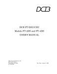
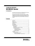
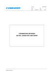
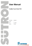
RENSSELAER
POLYTECHNIC
INSTITUTE‐
ECSE
4790
MICROPROCESSOR
SYSTEMS
(MPS)
Controller
Area
Network
National
Instruments
Manual
LabVIEW
Team:
Albert
Barsa
Carlos
Cao
Cao
Paul
Kwoni
Update
version
AUGUST
20,
2012
Manual
for
ECSE
4790
MPS
Course
lab
experiment
dealing
specifically
with
the
National
Instruments
USB
CAN
Hardware
1
CAN
USB:
The
demo
box
provided
by
Lesley
Yu
helped
us
greatly
understand
the
functionality
and
limitation
of
the
NI
USB‐
8473
Hardware.
The
CAN
USB
does
not
support
Channel
API
because
USB
devices
lack
this
function.
This
manual
will
also
detail
other
topics
using
the
National
Instrument’s
(NI)
equipment.
It
will
start
off
by
covering
the
CAN
USB,
it
will
then
cover
the
DAQ
card
and
finally
will
cover
CAN
to
DAQ
data
synchronization.
Hardware
Required:
Figure
1:
Termination
Cable
Figure
2:
NI
CAN
USB‐8473
Figure
3:
NI
CAN
Demo
Box
Procedure:
Installing
LabVIEW
Software
•
LabVIEW
is
already
installed
on
the
lab
desktops,
however
you’ll
need
it
on
your
laptop
to
be
able
to
run
the
example
VIs
for
this
demonstration
on
your
laptop.
This
takes
quite
a
bit
of
time
if
you
are
going
to
install
the
latest
version.
So
far
NI‐HWS,
NI‐IMAQ,
NI‐IMAQdx,
NI‐IMAQ
for
IEEE
1394,
NI‐IMAQ
IO,
NI‐
Motion,
and
NI‐RIO
are
not
required
to
be
installed.
Download
the
latest
version
of
LabVIEW
from
RPI.
Instructions
on
how
to
get
a
license
and
download
are
on
the
help
desk
site.
2
•
Follow
the
install
instruction
on
the
RPI
web
page
Installing
NI‐CAN
Software
•
The
examples
that
you
need
have
to
be
installed
separately
for
NI‐CAN
(2.7.3)
that
comes
with
NI
USB‐
8473.
It
contains
specific
examples
that
utilize
CAN.
It
also
installs
the
drivers
that
are
required
to
enable
the
NI
USB
modules
to
properly
communicate
with
your
computer.
Install
NI‐CAN
2.7.3
from:
http://joule.ni.com/nidu/cds/view/p/id/2646/lang/en
•
When
prompted
for
a
LabVIEW
Version,
choose
LabVIEW
2011,
unless
you
have
an
older
version.
Install
all
subfeatures.
•
You
can
disable
Visual
Basic/Visual
C/Borland
C
support.
It
is
not
needed
for
the
CAN
viewer.
Figure
4:
NI‐CAN
2.7.3
Examples
You
are
done
with
the
LabVIEW
install
and
may
open
any
CAN
VI
that
you
wish
to
use.
Installing
Measurement
&
Automation
Explorer
Software
•
The
hardware
demo
comes
with
another
disk
labeled
“NI
CAN
Demo
Box”
that
has
a
user
manual
and
a
couple
of
files
on
it.
You
need
to
copy
the
content
of
this
disk
to
the
National
Instruments
folder
that
is
located
at
C:\Program
Files\National
Instruments.
3
h
Figure
5:
NI‐CAN
Demo
Box
CD
After
you
are
done
copying
you
need
open
Measurement
&
Automation
Explorer
that
can
be
found
either
on
your
Desktop
or
in
program
files
under
the
National
Instruments
folder.
Figure
6:
NI
MAX
(Measurement
&
Automation
Explorer)
Icon
Once
it
loads
expand
the
Data
Neighborhood
by
selecting
the
+
sign
on
its
left
side.
Left
click
on
CAN
Channels.
Select
Load
Channel
Configuration.
Figure
7:
Explorer
Welcome
Window
•
Open
CAN
Demo
Box.ncd
from
its
location
which
should
be
in
the
directory
you
copied
the
content
of
the
CD
in.
Select
“Add
All
Messages
and
Channels.”
Click
Load,
and
then
click
Done.
4
Figure
8:
Loading
Channel
Configuration
•
It
should
load
13
message
files
into
the
explorer.
Figure
9:
Message
Files
Loaded
Setting
up
Hardware
• Connect
the
NI
USB‐8473
to
you
computer
via
the
USB
port.
5
•
•
•
In
the
demo
box
you
are
provided
with
a
termination
cable.
This
cable
will
be
used
to
connect
the
male
DB9
terminal
of
the
NI
USB
hardware
to
the
male
DB9
terminal
of
the
demo
box
labeled
“CAN.”
Connect
a
jumper
wire
between
the
Function
Generator
Gen
terminal
and
the
Analog
In
To
CAN
Ch0
terminal.
(National
Instruments,
2006)
Connect
a
second
jumper
wire
between
the
Function
Generator
Gen
terminal
and
the
Analog
In
To
CAN
Ch1
terminal.
(National
Instruments,
2006)
Figure
10:
Wiring
(National
Instruments,
2006)
•
•
Connect
the
DC
power
supply
to
the
box.
At
power
up,
the
box
will
begin
transmitting
the
WAVEFORM0_SAW0_SWITCHES_FROM_CDB
and
WAVEFORM1_SAW1_FROM_CDB
messages
at
the
NI‐CAN
default
baud
rate
of
125
K.
(National
Instruments,
2006)
This
is
what
your
final
setup
should
look
like.
Figure
11:
Properly
Connected
Hardware
•
You
can
verify
that
the
CAN
messages
are
being
transmitted
by
running
the
Bus
Monitor
in
the
Measurement
&
Automation
Explorer
(MAX).
To
run
the
Bus
Monitor,
right‐click
the
port
connected
to
the
Port
connector
on
the
NI
CAN
Demo
Box
and
select
Bus
Monitor.
(National
Instruments,
2006)
6
Figure
12:
Bus
Monitor
LabVIEW
• Start
LabVIEW
and
it
will
open
a
window
labeled
“Getting
Started.”
Click
on
“Find
Examples.”
Figure
13:
LabVIEW
Welcome
Window
•
It
will
open
another
window
“NI
Example
Finder”
in
which
there
is
a
search
field
on
the
top
left
corner.
Search
for
“CAN.”
Double
click
the
search
results
in
the
field
below.
Select
CAN
Receive.vi
from
the
list
given
in
the
center.
7
Figure
14:
NI
Example
Finder
•
This
will
open
the
CAN
Receive.vi,
make
sure
you
select
CAN0
in
the
interface
window
and
change
the
Baudrate
to
500000
before
hitting
run
(the
right‐pointing
arrow).
Figure
15:
CAN
Receive.vi
Example
8
Figure
16:
Demo
Setup
with
CAN
Receive.vi
running
on
the
laptop
Sending
a
Frame
to
the
CAN
bus
with
LabVIEW:
Hardware
Required:
Figure
17:
Termination
Cable
Figure
18:
NI
CAN
USB‐8473
Procedure:
Hardware
Connections
•
•
The
connection
between
the
NI
USB‐8473
and
CAN
bus
requires
a
termination
cable.
It
is
an
essential
component
to
getting
the
data
from
the
CAN
bus
to
your
PC.
The
termination
cable
will
act
as
a
male‐
male
converter
between
the
NI
USB‐8473
and
CAN
bus
DB9
terminals.
The
NI
USB‐8473
will
connect
to
your
PC
through
the
USB
port.
9
•
•
You
will
connect
the
male
DB9
terminal
of
your
NI
USB‐8473
to
one
of
the
female
terminals
on
your
termination
cable.
The
other
female
terminal
of
the
termination
cable
will
be
connected
to
the
male
DB9
terminal
of
the
CAN
bus.
LabVIEW
•
Start
LabVIEW
and
it
will
open
a
window
labeled
“Getting
Started.”
Click
on
“Find
Examples.”
Figure
19:
LabVIEW
Welcome
Window
[Use
latest
version
available]
•
It
will
open
another
window
“NI
Example
Finder”
in
which
there
is
a
search
field
on
the
top
left
corner.
Search
for
“CAN.”
Double
click
the
search
results
in
the
field
below.
Select
CAN
Transmit
–
event
based.vi
from
the
list
given
in
the
center.
10
Figure
20:
NI
Example
Finder
•
This
will
open
the
CAN
Transmit
–
event
based.vi
with
its
default
input
values.
Figure
21:
CAN
Transmit
‐
event
based.vi
•
This
step
is
the
most
important
and
it
needs
to
be
followed
carefully.
The
interface
needs
to
be
changed
to
CAN0,
the
Baudrate
must
be
500000
or
you
will
not
be
able
to
communicate
with
the
CAN
bus
on
the
car
at
all.
11
Figure
22:
CAN
Transmit
‐
event
based.vi
with
interface
and
Baudrate
changed
•
After
changing
the
values
of
interface
and
Baudrate,
you
need
to
change
the
data
length
and
Arbitration
Id.
The
changes
in
these
two
values
depend
on
which
feature
you
want
to
control.
The
following
table
will
assist
you
in
selecting
these
values.
CAN
Demo
Box
Functions
Changes
may
be
observed
directly
for
most
items
if
the
display
is
already
showing
the
affected
menu
item.
Function
Arbitration
ID
[decimal
val]
Data
bytes
Data
Ch0
Data
out
&
Switches
(Read
only)
0x710
[1808]
3
2
bytes
of
analog
data,
3rd
byte:
X
X
S3
S2
S1
S0
X
X
Ch1
Data
out
(Read
only)
0x720
[1824]
3
2
bytes
of
analog
data,
3rd
byte:
0x00
StringRequest
0x730
[1840]
StringResponse
(Read
only)
0x740
[1856]
6
6‐byte
string
with
ASCII
“NI‐CAN”
codes;
reply
to
StringRequest
command.
TransmitType
0x760
[1888]
1
0‐Disable
all
1‐Waveform0,
Sawtooth0,
Switches
only
2‐Waveform1,
Sawtooth1
only
3‐Enable
all
DelayMultiplier
0x763
[1891]
2
Delay
between
analog
samples:
DelayMultiplier
x
200
ns
Range:
0
–
65535
Default:
50,000
(10ms)
BaudRateType
(Can
change
but
can’t
change
back
without
using
Box
menu
buttons)
0x765
[1893]
1
2‐125
Kbps
3‐250
Kbps
4‐500
Kbps
5‐1
Mbps
0
Ignored,
but
make
sure
RTR
is
not
set.
(ignored)
Box
replies
with
next
message.
12
FunctionGeneratorOutput
0x766
[1894]
1
0‐Sine
1‐Square
2‐Triangle
FunctionGeneratorFrequency
0x767
[1895]
1
0
to
9‐0.1
to
1
Hz
in
0.1
Hz
increments
9
to
18‐1
to
10
Hz
in
1
Hz
increments
18
to
117‐10
Hz
to
1
kHz
in
10
Hz
incr.
LCDContrast
0x768
[1896]
1
0‐Decrease
contrast
1‐Increase
contrast
LCDMenu
(Displays
selected
menu
on
Demo
Box
LCD
panel)
0x769
[1897]
1
0‐CAN
baud
rate
1‐CAN
transmit
status
2‐CAN/DAQ
3‐Function
generator
output
4‐Function
generator
frequency
5‐LCD
contrast
6‐
(clear
screen)
7‐“High
Speed
CAN”
message
•
It
is
highly
recommended
that
you
start
off
with
the
simplest
feature
to
control.
It
would
be
recommended
that
you
try
changing
the
displayed
function
generator
frequency
at
Id
0x767.
As
an
example,
to
send
a
single
data
byte
(byte
value
of
1)
to
a
device
whose
Arbitration
ID
is
0x30
the
setting
would
be:
Figure
23:
Changing
Arbitration
Id
and
Data
Length
[New
Arbitration
Id
should
be
04]
•
The
Data
has
8
inputs
but
when
you
set
the
Data
length
to
be
1,
it
will
take
only
the
first
input
and
ignore
the
rest.
Now
you
can
click
the
button
with
the
white
arrow
on
it
that
will
make
the
VI
run.
The
device
at
0x30
can
be
activated
when
you
set
the
first
input
to
1
and
click
Write.
To
turn
it
off
you
need
to
change
the
input
to
0
and
click
Write
once
more.
13
Figure
24:
Running
VI
and
Changing
Data
input
[New
Arbitration
Id
should
be
04]
Getting
the
DAQ
card
talking
to
DAQ
assist:
[This
section
can
only
be
completed
if
a
DAQCard‐6062E
is
available,
otherwise
it
should
be
skipped.
This
part
of
the
procedure
requires
the
use
of
Frame
API
for
the
CAN
interface
rather
than
Channel
API.
So
far,
only
Channel
API
has
been
implemented.
The
USB‐8473
converters
do
not
support
Frame
API.
Continue
with
Using
LabVIEW
With
the
CAN
Demo
Box
and
Analog
Signals
on
page
23.]
In
order
for
the
computer
to
recognize
the
DAQ
card,
we
need
to
insert
the
DAQ
card
first
and
install
the
driver
for
it.
At
this
time
of
installation,
I
am
using
LabVIEW
8.5.1
to
talk
to
the
DAQ
card.
The
driver
version
that
worked
well
talking
to
LabVIEW
8.5.1
was
NI‐DAQmx
8.8,
which
can
be
downloaded
from:
http://ftp.ni.com/support/softlib/multifunction_daq/nidaqmx/8.8/nidaq880f2_downloader.exe
14
Use
the
defaults
setting
to
install
this
driver.
Once
the
driver
is
finished
installing,
you
can
check
by
clicking
(NI
MAX
icon),
click
on
“Devices
and
Interfaces
‐>
Ni‐DAQmx
Devices
‐>
NI
DAQCard‐
6062E:
“Dev1”,
and
choose
“Test
Panels”
at
the
upper
corner:
And
you
can
test
the
functionality
of
the
DAQ
card:
15
You
can
also
go
to
“Software”
to
check
if
the
driver
is
correctly
installed,
and
you
will
see
the
following:
Once
it
is
verified,
you
can
make
the
DAQ
talking
to
the
DAQ
assist.
The
following
steps
are
followed:
1)
2)
3)
4)
Open
LabVIEW
Press
Ctrl
+
N
to
create
a
“New
VI”
Then
press
CTRL
+
E,
(Window‐>
Show
Block
Diagram),
to
bring
the
Block
Diagram
Right
click
anywhere
on
the
blank
space,
and
pick
the
first
icon
on
the
list
and
you
will
see
the
DAQ
assist
icon:
5) Choose
“DAQ
Assist”,
and
you
need
to
place
the
DAQ
Assist
and
will
see
an
Initializing
dialog.
16
6) Finally,
you
will
have
the
following:
7) Then
you
select
either
“Acquire
Signals”
or
“Generate
Signals”
to
choose
the
tool
you
need
like
Voltage,
temperature,
Resistance,
etc.
8) Click
on
Finished
once
you
are
done.
And
you
will
see
another
window
of
the
kind
of
tool
you
have
selected.
In
my
case:
I
have
chose:
Acquire
Signals
‐>
Analog
Input
‐>
Voltage
‐>
ai0
to
get
the
following
windows:
17
CB‐68LP
To
investigate
further
the
useful
feature
of
the
DAQ
card,
we
can
use
an
Unshielded
Screw
Terminal
Blocks,
CB‐68LP
that
has
68
pins
to
simulate
different
I/O
signals
with
the
DAQ
card.
To
connect
correctly
with
the
pins,
we
can
look
at
the
reference
table
below:
The
important
pins
that
are
needed
to
make
this
terminal
connector
and
the
DAQ
card
work
are
indicated,
and
you
can
use
the
Test
Panel
to
simulate
the
signals
with
different
input
numbers.
18
TOPIC:
CAN
DEMO
BOX,
USB‐8473s,
and
DAQ
CARD
SYNCHRONIZATION
Before
we
start:
In
order
to
accomplish
the
goal
of
this
guide,
we
need
the
following
equipments:
CAN
demo
box,
NI
USB‐8473s,
DAQCard‐6062E,
and
cables
that
allowing
connection
between
computer
CAN
demo
box,
and
NI
USB‐8473s.
Special
setup
on
NI
USB‐8473s:
To
make
this
device
to
work,
we
need
to
put
some
wires
between
the
demo
box
and
itself.
The
wires
configuration
is
followed:
19
Next,
we
go
to
to
test
if
the
DAQ
card
is
fuctioning
correcting.
This
is
important
because
sometimes
the
computer
does
not
recognize
the
DAQ
card
and
cause
problems
to
happen.
20
Once
we
know
that
the
DAQ
card
is
working
correctly.
We
now
can
launch
LabVIEW
8.5,
at
this
stage
if
testing
LabVIEW
8.6
DOES
NOT
work.
Click
on
“Find
Examples
‐>
Search
‐>
Enter
keyword”,
and
write
“CAN”,
then
click
on
“CAN
Frame
API
Input
DAQmx
Input.VI”.
And
you
will
see
the
following
without
any
problems:
If
you
can’t
see
the
picture
above,
the
following
are
the
possible
causes
that
we
have
encountered:
21
1) The
LabVIEW
version
should
be
the
latest
available
2) The
correct
wiring
between
CAN
USB
and
Demo
box
3) The
DAQ
card
should
be
inserted
and
working
properly
When
we
go
back
to
our
LabVIEW,
we
only
need
to
click
“RUN”
or
“CLT
+
R”,
we
can
see
that
LabVIEW
is
reading
data
from
the
devices.
We
also
noted
the
different
times
frames
that
the
data
was
acquired:
You
can
click
on
“Window
‐>
Show
Block
Diagram”
or
CLT
+
E
to
see
how
the
device
works.
22
Using
LabVIEW
With
the
CAN
Demo
Box
and
Analog
Signals
This
part
of
the
lab
procedure
will
use
NI
LabVIEW
tools
to
observe
and
plot
analog
waveforms
generated
in
the
CAN
Demo
Box
and
sampled
in
the
box.
The
data
samples
are
sent
out
as
CAN
frames
on
the
bus.
A
VI
will
be
used
to
read
the
samples
and
create
a
real‐time
plot
of
the
waveforms.
[The
procedures
and
VIs
supporting
the
analog
signals
generated
by
the
NI
CAN
Demo
Box
and
displaying
them
in
graphical
form
are
not
available
yet.
This
part
of
the
exercise
will
be
implemented
at
a
later
date.]
23
Using
LabVIEW
With
the
Model
Car
The
second
part
of
the
lab
procedure
involves
CAN
communications
with
the
model
car
still
using
the
LabVIEW
tools
and
two
VIs
that
were
developed
to
assist
in
the
process
of
writing
and
debugging
C
code
on
the
C8051F040
EVB.
Use
any
of
the
previous
VIs
as
well
as
two
new
ones
(CAN‐sender‐MPS.vi
and
CAN‐viewer‐MPS.vi).
These
are
stripped
down
versions
that
have
been
simplified
to
be
easier
to
use.
Before
going
back
to
the
lab
to
continue
the
procedure,
some
of
the
functions
may
be
checked
out
here
to
verify
the
correct
operation
of
the
RC
car
and
its
response
to
commands.
The
following
table
summarizes
the
CAN
IDs
to
which
the
car
will
respond.
RC
Car
Functions
Function
Arbitration
ID
Data
length
Data
Headlights
0x01
1
Byte
0:
0=Off,
1=On
Left
turn
signal
0x02
1
Byte
0:
0=Off,
1=On
Right
turn
signal
0x03
1
Byte
0:
0=Off,
1=On
Horn
0x04
1
Byte
0:
0=Off,
1=On
Drive
Motor
DAC
0x05
2
Byte
1,
Byte
0:
12‐bit
value
(0‐
4095/0‐0xFFF)
Steering
Servo
PWM
0x06
2
Byte
1,
Byte
0:
16‐bit
value
(850‐
2150)
(Windshield
wiper)
0x20
1
Byte
0:
0=Off,
1=On
RC
Car
Status
Replies
Function
Arbitration
ID
Data
length
Data
Motor
Temperature
0x07
2
Byte
1,
Byte
0:
12‐bit
value
(0‐
4095/0‐0xFFF)
Wheel
RPM
0x08
2
Byte
1,
Byte
0:
12‐bit
value
(0‐
1400/0‐0x578)
Motor
Current
0x09
2
Byte
1,
Byte
0:
12‐bit
value
(0‐
4095/0‐0xFFF)
Left
Turn
Signal
Status
0x0A
1
Byte
0:
0=Off,
0xFF=On
Right
Turn
Signal
Status
0x0B
1
Byte
0:
0=Off,
0xFF=On
Works
Cited
National
Instruments.
(2006,
October).
NI‐CAN
Hardware
and
Software
Manual.
https://forum.ecse.rpi.edu/index.php?topic=7056.0
24