1
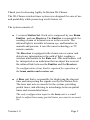
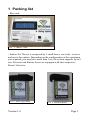
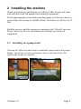
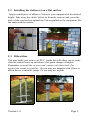
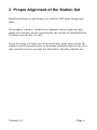
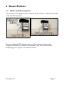
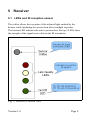
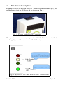
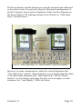
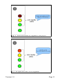
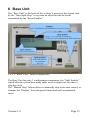
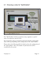
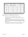
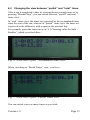
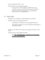
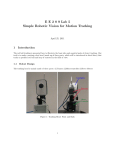
User Manual
Last Update: January 11th, 2009
Version 1.0
Page 1
Thank you for choosing Agility In Motion Wi-Chrono.
The Wi-Chrono wireless timer system was designed for ease of use
and portability while preserving a rich feature set.
The system consists of:
●
1 or more Station Set. Each set is composed by one Beam
Emitter and one Receiver. The Emitter is responsible for
sending a beam of infrared waves to the receiver. The
infrared light is invisible to human eye, and harmless to
animals and persons, it uses the same technology as TV
remote controls.
The Receiver is equipped with a beam waves sensor and
detects any interruption in the path of light, sending a
wireless notification to the Base unit. This notification will
be interpreted as an indication that an object has crossed
the infrared link between the Emitter and the Receiver.
No configuration of any kind is required for operation of
the beam emitter and receiver set.
●
A Base unit that is responsible for displaying the elapsed
time and interpreting the signals sent by the Station Sets.
The base unit acts as console for the system, providing
partial times, and allowing to interchange between partial
times and accumulated times.
The only configuration input to the base unit is a small
knob to adjust how many partial times you want to account
for.
Version 1.0
Page 2
1 Packing list
- Base unit:
Pict. 1: Base Unit
- Station Set. The set is composed by 2 small boxes, one is the receiver
and one is the emitter. Depending on the configuration of the equipment
you acquired, you may have more than 1 set, the system supports up to 8
sets. Receiver and Emitter boxes are equipped with their respective
Elastic Velcro tie.
Pict. 2: Start-Split-Stop
Version 1.0
Pict. 3: Beam Emitter
Page 3
2 Installing the stations
Install each Receiver and Emitter set with the LEDs facing each other,
and with their back flat against their mounted equipment.
The height depends on how high your dog jumps over the bars, but as a
general rule, the set may be installed about 10 inches over the bar (or 25
cm).
Both the receiver and the emitter are equipped with Velcro® tape and
Elastic Velcro tie for easy installation on virtually any surface or
equipment.
2.1 Installing on a jump stand
Unwrap the Velcro tie and wrap it around the jump stand at the proper
height. Install the receiver and emitter boxes with their back flat
against the stands for stability.
Version 1.0
Page 4
2.2 Installing the station set on a flat surface
Apply a small piece of adhesive Velcro to your equipment at the desired
height. Take away the elastic Velcro tie from the receiver and press the
back of the receiver box against the Velcro applied on the equipment. Do
the same with the emitter.
2.3 Other ideas
You may build your own set of PVC stands that will allow you to easily
slide the station boxes up and down a for quick change of heights.
Remember to install the receiver and emitter with their back flat
against the stands for stability. Or you may use magnets with Velcro to
attach the set to metallic jumps. Or you may use tripods.
Version 1.0
Page 5
3 Proper Alignment of the Station Set
Install each Receiver and Emitter set with the LED lights facing each
other.
The height at which to install the set depends on how high your dog
jumps over the bars, but as a general rule, the set may be installed about
10 inches over the bar (25 cm).
If you are using 2 or more sets at the same time, make sure to point the
emitters across from each other so the beam of infrared light of one set is
only sensed by its receiver and not detected by the other stations too.
Version 1.0
Page 6
4 Beam Emitter
4.1 LEDs and IR transmitter
The top two clear lights are the infrared LED emitters. The bottom LED
is the On/Off indicator.
The two infrared LED emitters are very low power devices and
completely harmless for dogs and humans, and they use the same
technology as a regular TV remote control.
Version 1.0
Page 7
5 Receiver
5.1 LEDs and IR reception sensor
The orifice allows the reception of the infrared light emitted by the
beamer while insulating the sensor from direct sunlight exposure.
The bottom LED indicates the unit is powered on, the top 3-LEDs show
the strength of the signal received from the IR transmitter.
Fig. 1: Receiver's lateral view
Version 1.0
Page 8
5.2 LED status description
When the “Power Switch” in the “Off” position as indicated in Fig.2, you
would observe that no LEDs are lit, as shown in Fig.1.
Fig. 2: Power switch in OFF position
When you turn the device on, and provided that the batteries are installed
and charged, you will observe one of the following:
Fig. 3: a) Unit is ON - not able to "see" the Emitter
Version 1.0
Page 9
The Beam Emitter and the Station are carefully designed and calibrated
so they don't need to be perfectly aligned, allowing a misalignment of
about 10 degrees from a perfect alignment. Where perfect alignment is
the Beam Emitter's IR pointing straight to the Station (or “Start-SplitStop”) own IR sensor.
Pict. 4: "Start-Split-Stop" & "Beam Emitter" perfectly aligned
However, in some circumstances, either the vertical alignment (the
“Start-Split-Stop” and the “Beam Emitter” are one higher than the other)
or the directional alignment (the “Start-Split-Stop” and the “Beam
Emitter” are not 'facing' each other, but they are at an angle), in such
situations, the “Link Quality” LEDs will show:
Version 1.0
Page 10
Fig. 4: Yellow also turned on, alignment is not perfect
Fig. 5: IR signal too weak, review alignment
Version 1.0
Page 11
6 Base Unit
The “Base Unit” is the brain of the system, it processes the signals sent
by the “Start-Split-Stop” every time an object breaks the beam
transmitted by the “Beam Emitter”.
Pict. 5: Base Unit - Main components
The Base Unit has only 1 configuration component, the “Split Enabler”
which tells the system how many splits are in a single run, in order to
stop the clock.
The “Manual Stop” button allows to manually stop a run once started, or
changes the “Display” between partial times and total accumulated
times.
Version 1.0
Page 12
6.1 Choosing a value for “Split Enabler”
Pict. 6: Split Enabler set to 3
The “Split Enabler” tells the system how many segments, or partial
times, are required to stop the clock.
The stopwatch is always activated by the first beam that is interrupted,
then it will stop depending on the configuration of the “Split Enabler”
Please refer to the following table for details on how the configuration of
the “Split Enabler” affects the number of split times that will be
considered by the system.
Version 1.0
Page 13
Pict. 7: Effect of "Split Enabler" on number of splits to consider
As an example, assume that the “Split Enabler” is set to 3, as it is
depicted in “Pict. 5', the following events will occur:
–
–
–
–
The first beam is crossed and the clock is started
Next beam is crossed 3.89” later, and the accumulated time is
stored for split #1
Next beam is crossed, and the accumulated time is stored for
split #2 (for example, if the time between crossing the 1st beam
and the 3rd beam is 8.13”, then the accumulated time for split 2,
will be 8.13
Next a beam is crossed at time 13.85”, and being the 3rd beam
crossed after the clock started, the stopwatch is stopped
Version 1.0
Page 14
6.2 Changing the view between “partial” and “total” times
After a run is completed, either by crossing beams enough times or by
pressing “Manual Stop”, you can switch between “partial” and total
times view.
In “total” times view, the times are expressed as the accumulated times
since the start of the run, whereas in “partial” times view, the times are
expressed as the difference with respect to the previous lap.
For example, given the same run as in “6.1 Choosing value for Split
Enabler”, which we refresh here :
Fig. 6: A run with 3 splits - Accumulated Times view
When switching to “Partial Times” view, you'd see :
Fig. 7: A run with 3 splits - Partial Times view
You can switch views as many times as you wish.
Version 1.0
Page 15
7 Troubleshooting and common symptoms
For all components of the system, the “Beam Emitter”, the “Start-SplitStop” or the “Base Unit” the main reason for malfunction is low battery.
Please contact us at [email protected] if you have questions.
7.1 “Beam Emitter”
Symptom: The “power” LED is not on
Possible reasons and suggested actions:
•
The batteries are drained, try replacing the batteries
•
The batteries polarity is reversed, follow the drawings in
the battery holder
7.2 “Start-Split-Stop”
Symptom: The “power” LED is not on
Possible reasons and suggested actions:
•
The batteries are drained, try replacing the batteries
•
The batteries polarity is reversed, follow the drawings in
the battery holder
Symptom: The “Start-Split-Stop” is unable to 'see' the beam from
the “Beam Emitter”
Possible reasons and suggested actions:
•
If no “Link Quality” LED is ON, then the units might be
seriously misaligned, try realigning them
•
If the alignment is correct, but still no link is detected,
try with another “Beam Emitter”.
Symptom: The “Start-Split-Stop” detects the broken beam, but it
Version 1.0
Page 16
does not signal the “Base” unit
Possible reasons and suggested actions:
•
If you see the 3 “Link Quality” LEDs lit for a few
seconds every time you break the beam, but still you
don't see the base acting upon it, try replacing the
batteries in the “Start-Split-Stop”
7.3 “Base Unit”
Symptom: The “display” remains blank after switch on
Possible reasons and suggested actions:
•
The batteries are drained, try replacing the batteries
•
The batteries polarity is reversed, follow the drawings in
the battery holder
Symptom: The “Base Unit” does not recognize a broken- beam
event
Possible reasons and suggested actions:
•
Version 1.0
See The “Start-Split-Stop” is unable to 'see' the beam
from the “Beam Emitter”
Page 17
8 Frequently Asked Questions
•
Question: I want to add another “Start-Split-Stop” and “Beam
Emitter”, is it possible ? Do I need to give you a code or
anything ?
Answer: Yes, you can add up to 8. All the “Beam Emitter” are
the same amongst them and also the “Start-Split-Stop”, so there
is no need to inform us of any code or frequency, since they are
all exactly the same.
•
Question: My friends have a “Agility In Motion Wi-Chrono”
also, can I use their “Start-Split-Stop” and “Beam Emitters” ?
Answer: Yes, you can. The “Base Unit” is not restricted to a set
of components, they are all the same and can be shared.
•
Question: I have 2 sets of “Agility In Motion Wi-Chrono” but
noticed that when I used them together, they get activated at the
same time ?
Answer: Yes, that is correct. If you plan to use both systems at
the same time, but want to preserve their independence, we can
reprogram them. Please contact us.
•
Question: What is the accuracy of the system ?
Answer: The system runs with a high precision clock with a
specified accuracy of 50 PPM, (it is off, at most, by 50 'ticks' per
millions), which actually depends on several physical factors,
like temperature. Expect the system to run about 1/100” plus or
minus per minute.
•
Question: I compared my system to my friends system, we both
were using the same start and stop, but the times are off by
1/100, but only sometimes ?
Answer: The source clock is very accurate, but many factors
affect the time processing, the most important one being that is
“interrupt driven”. When a beam event happen, the system “gets
interrupted” at a 1/100” boundary, that's why 2 systems might
“look” off by 1/100.
Version 1.0
Page 18
9 Technical specifications
•
FCC ID:OUR-XBEE
•
“Start-Split-Stop” to “Base” Range : Up to 100m (110y) with
line of sight (wireless)
•
“Beam Emitter” to “Start-Split-Stop” Range: Up to 5m (IR)
•
Operating Temperature : 0 to 45 degree Celsius
Version 1.0
Page 19