1
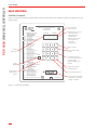
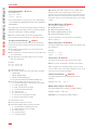
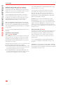
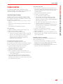
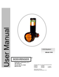
USER GUIDE SINGLE WELL CONTROLLER Contents Basic Operations.............................................................. 2 Pressure-Operation Control Functions........................... 9 Controller’s Faceplate..................................................... 2 Features for Opening the A-Valve................................. 11 Turning the Controller On and Off................................... 3 Features for Closing the A-Valve.................................. 12 Status Display................................................................. 3 Features for Special Circumstances............................. 12 Units of Measurement.................................................... 3 Sales-Line Safeguard Features..................................... 13 Operating the A-Valve and B-Valve Manually................. 3 Reading Reports and Program Functions...................... 3 Setting Program Functions............................................. 3 Using Pressure Operation to Intermit a Well without a Plunger............................................................................ 14 Pressure-Operation Selection Functions...................... 14 Report and Program Function Reference...................... 4 Pressure-Operation Control Functions......................... 14 Reports........................................................................... 4 Features for Opening the A-Valve................................. 14 Program Functions......................................................... 4 Features for Closing the A-Valve.................................. 14 Controller Reports............................................................ 5 How Pressure Operation Works...................................... 7 Features for Special Circumstances............................. 14 Sales-Line Safeguard Features..................................... 14 Troubleshooting.............................................................. 15 Calibrating the Transducers............................................ 8 Controller Display Problems......................................... 15 Calibrate Transducers Wired to the Controller............... 8 Program Cycle Problems.............................................. 16 Calibrate Transducers Reporting Wireless to the Controller........................................................................ 8 Solenoid (Shift Valve) Problems.................................... 19 Turn off a Transducer...................................................... 8 Transducer Problems.................................................... 19 Preventive Maintenance................................................ 19 Creating a Pressure-Operation Plunger Program......... 9 Pressure-Operation Selection Functions........................ 9 ©2008 Production Control Services, Inc. ProductionControlServices.com PCS 4000 SINGLE WELL CONTROLLER PCS 4000 ™ PCS 4000 SINGLE WELL CONTROLLER USER GUIDE Basic Operations Controller’s Faceplate Figure 1 shows the controller’s faceplate with the power on/off switch, status display, keypad, and serial port for local operator input. Time remaining in hrs.:min.:sec. PRODUCTION CONTROL SERVICES, INC. 1-800-619-2241 PCSplungerlift.com OPERATING INSTRUCTIONS Current well status Power On/Off Reads reports and function values READ B 30: Serial Number Read CE: Version Number MANUAL VALVE CONTROL ON Open A Valve (Sales) OFF Close A & B Valves B ON Open B Valve (Vent) PROGRAM AND READ SETTINGS PROGRAM Press: SET, Function Key READ Press: READ, Function Key ON A Valve Open Time OFF Close Time B ON B Valve Open Time #00 Battery And Solar Conditions #02 A Valve Delay (Sales) Time #03 Mandatory Shut In Time #05 Plunger Fall Time #08 Delay Close Time Sensor Status (On or Off) #09 Auxillary Close Delay (On = No Delay or Off = Close Delay) #11 Controller Operating Mode Differential Open Pressure #12 Casing-Tubing or Casing-Line #13 Casing PSI Increase (Casing Dip) Close #14 High Line Pressure Close POWER #15 Low Line Pressure Close Activate and Calibrate Trans #1/Casing #16 #17 Activate and Calibrate Trans #2/Tubing #18 Activate and Calibrate Trans #3/Line ON/OFF #20 Casing Drop Pressure #21 Casing Peak Build Time #24 Load Factor #26 Equalize Time / C Valve #90 Scan / Set Entire Program B VALVE SETTINGS B-0 A Valve Closed When B is Open (Yes or No) B-2 B Valve Display Time B-4 B Valve Plunger and Valve Counts B-7 B Valve Open and Close Times B-8 Line Delay Times PLUNGER HISTORY History Press: READ, Function Key Clear Totals Press: SET, Function Key, CE #04 A Valve Plunger and Valve Counts #06 Plunger Travel Times (Last 25) Avg. Run #07 A Valve Open and Close Times A & B Plunger and Valve Counts #10 Plunger Travel Times (Last 25) #19 Open and Close Times (Last 10) THIS PCS CONTROLLER IS MANUFACTURED BY PCS, INC © 1998 Figure 1 – Controller’s Faceplate 2 DISPLAY STATUS HRS:MIN:SEC CLOSE 0:00:00 C315 T250 L150 1 2 3 ON 4 5 6 OFF 7 8 9 B READ 0 SET CE When A-valve is closed: - Casing pressure - Tubing pressure - Line pressure When A-valve is open: - Casing pressure - Flow rate - Line pressure Opens A-valve Closes A-valve and B-valve Used with other keys to access functions that control B-valve. Example: B ON opens B-valve Clears current entry and backspaces Sets program functions PATENT NO.6,196,324 B1 Local operator input (LOI) serial port for connection to laptop computer USER GUIDE Operating the A-Valve and B-Valve Manually To turn the PCS 4000 Single Well Controller on or off, insert a screw driver into the slot marked POWER ON/ OFF. See Figure 1. Open the A-Valve = ☛ ON Move the toggle switch to the left to turn the controller on. Move the toggle switch to the right to turn the controller off. The plunger program does not run while the controller is off. When you turn the controller on, it closes the A-valve and starts counting down the FALL TIME (see step 1 on page 7). Status Display After you turn the PCS 4000 Single Well Controller on, the status display remains on. The controller never sleeps. The first line of the status display shows the current well status and the time remaining. When the A-valve is closed, the second line of the status display shows the casing pressure, tubing pressure, and sales line pressure. Example: CLOSE 0:00:00 C315 T250 L150 When the A-valve is open, the second line shows the casing pressure, flow rate, and sales line pressure. Example: A-OPEN 0:14:22 C315 F123 L150 Units of Measurement Time is in hours:minutes:seconds. Example: 08:15:00 Pressure is in pounds per square inch (psi). Example: 00100 Depending on the setting of the METRIC function (SET 33), the unit of measurement for flow rate is either thousand cubic feet (mcf) or thousand cubic meters (E3M3). PCS 4000 SINGLE WELL CONTROLLER Turning the Controller On and Off Press ON. ON overrides all programmed functions such as FALL TIME and MANDATORY SHUT-IN TIME. ON does not override safeguard functions such as LOW LINE CLOSE PRESSURE and HIGH LINE CLOSE PRESSURE. Open the B-Valve = ☛ B ON Press B ON. Close the A-Valve (and B-Valve if Used) = ☛ OFF Press OFF. OFF overrides all programmed functions such as OPEN TIME and DELAY TIME (SALES). Reading Reports and Program Functions Read a Report or the Value of a Single Program Function 1 Press READ. The status display shows: READ: 2 Enter the number of the report or function you want to display. Example: 10. Read the Values of All Program Functions = ☛ READ 90 For a list of the program functions, see “READ 90 Program Function List” on page 4. Setting Program Functions Set a Single Program Function 1 Press SET. The status display shows: SET: 2 Enter the number of the function you want to set. Example: 05. 3 Enter the value for the function. See “Units of Measurement” on this page. To exit the function without changing its value, press CE. Set All Program Functions = ☛ SET 90 For a list of the program functions, see “SET 90 Program Function List” on page 4. 3 PCS 4000 SINGLE WELL CONTROLLER USER GUIDE Report and Program Function Reference Program Function The tables in this section cross-reference the reports and program functions described in this User Guide. Reports Report READ Page Software Version Report CE 6 Battery Status Report 00 6 Status of A-Valve when B-Valve Is Open B0 9 A-Valve and Plunger Counts History 04 5 B-Valve and Plunger Counts History B4 5 Plunger Travel Time History 06 5 A-Valve Total Time Report 07 5 B-Valve Total Time Report B7 5 Valve/Plunger Counts History, Total Time Reports, and Plunger Travel Time History 10 Time Open and Closed History Modbus Address Report SET or READ Display Name Page OPEN TIME ON A OPEN TIME 9 CLOSE TIME OFF CLOSE TIME 11 DELAY TIME (SALES) 02 A DELAY TIME 13 MANDATORY SHUT-IN TIME 03 MAND. SHUT-IN 10 B OPEN TIME B ON B OPEN TIME 9 B DELAY TIME B2 B DELAY TIME 13 FALL TIME 05 FALL TIME 9 DELAY CLOSE TIME 08 DELAY CLOSE TIME 10 Sensor Operation 09 SENSOR? 9 SET SENSOR A-Valve Location (local or remote) 60 VALVE A LOCATION none B-Valve Location (local or remote) 61 VALVE B LOCATION none 5 C-Valve Location (local or remote) 62 VALVE C LOCATION none 19 6 Operating Mode 11 6 1. TIME 2. T-L 3. C-T 4. C-L 9 22 DIFFERENTIAL OPEN PRESSURE 12 OPEN PRESSURE 9 DIFFERENTIAL CLOSE PRESSURE (DIP) 13 CLOSE PRESSURE 10 HIGH LINE CLOSE PRESSURE 14 HIGH LINE PRES. 13 DELAY LINE CLOSE TIME B8 LINE DELAY TIME 13 Program Functions LOW LINE CLOSE PRESSURE 15 LOW LINE PRES. 13 READ 90 Program Function List CASING DROP PRESSURE 20 CASING DROP PRS. 12 CASING PEAK TIME 21 CASING TIME 11 LOW FLOW RATE 23 MIN. FLOW RATE 12 LOAD FACTOR 24 LOAD FACTOR 11 CRITICAL FLOW K FACTOR 25 TURNER CRIT FLOW CONSTANT 12 EFM Device Setup 31 READ REMOTE FLOW 9 Clearing Report Values Program Function SET Display Name Clearing Report Values 10 ZERO ALL TOTALS Page 6 Press READ 90 to display the current times, pressures, and flow rate values programmed for all functions listed in the table on the right side of this page. SET 90 Program Function List Press SET 90 to program all functions listed in the table on the right side of this page. Additional Program Function READ ACCUM FLOW To program this function, press SET B 0. To display its current value, press READ B 0. Program Function Status of A-Valve when B-Valve Is Open 4 SET or READ B0 Display Name A OPEN W/ B VAL. SELECT EFM TYPE Page 9 Flow Rate Unit of Measurement 33 METRIC 3 B LOW FLOW RATE 35 B LOW FLOW RATE 12 B LOW FLOW DELAY TIME 36 B LOW FLOW DELAY 12 USER GUIDE Plunger Travel Time History = ☛ READ 06 Example: A PLUNGER= A VALVE = Example: GOOD RUNS: 25 AVE: 0:08:22 In the example: A VALVE = 96 shows that the A-valve opened 96 times. A PLUNGER= 92 shows that the plunger arrived 92 times while the A-valve was open. 96–92=4. The plunger did not arrive 4 times while the A-valve was open. This report provides information about the 25 most recent plunger travel times. The first display shows the number of times the plunger surfaced and the average travel time. Use the READ button to scan through the report. The next 25 displays show the 25 most recent plunger travel times. This example shows the most recent plunger run. The plunger surfaced after 8 minutes and 15 seconds of OPEN TIME. LAST PLUNGER- 0 A 0:08:15 This example shows the 2nd most recent plunger run. LAST PLUNGER- 1 A 0:08:15 This example shows the 25nd most recent plunger run. LAST PLUNGER-24 A 0:08:15 This example shows the most recent plunger run. The plunger surfaced after 10 minutes and 40 seconds of OPEN TIME and B OPEN TIME. LAST PLUNGER- 0 B 0:10:40 This example shows the most recent plunger run. The CASING DROP PRESSURE was reached before the plunger arrived. LAST PLUNGER- 0 C 0:09:26 This example shows the most recent plunger run. The plunger did not surface. LAST PLUNGER- 0 NO PLUNGER To exit the report at any display, press CE. Valve/Plunger Counts History, Total Time Reports, and Plunger Travel Time History = ☛ READ 10 This reporting option displays the 2 Valve and Plunger Counts Histories (READ 04 and READ B4), the 2 Total Time Reports (READ 07 and READ B7), and the Plunger Travel Time History (READ 06). To display the next report, press READ. A-Valve and Plunger Counts History = ☛ READ 04 This report shows how many times the A-valve opened, and how many times the plunger arrived while the A-valve was open. 92 96 Note: If the well has a B-valve, this report shows 2 A-valve counts for each B-valve count in the B-Valve and Plunger Counts History. If the plunger did not arrive 4 times while the A-valve was open, the plunger may have arrived up to 2 times while the B-valve was open. B-Valve and Plunger Counts History = ☛ READ B4 This report shows how many times the B-valve opened, and how many times the plunger arrived while the B-valve was open. Example: B PLUNGER= B VALVE = 2 2 In the example: B VALVE = 2 shows that the B-valve opened 2 times. B PLUNGER= 2 shows that the plunger arrived 2 times while the B-valve was open. A-Valve Total Time Report = ☛ READ 07 This report shows 2 times of up to 999 hrs., 59 min., 59 sec. accumulated since the report was last cleared: Total OPEN TIME and DELAY TIME (SALES). Total time that the controller was closed. MANDATORY SHUT-IN (if any), FALL TIME (if any), and CLOSE TIME are accumulated under TOT CLS time. Example: A TOTAL 16:31:13 TOT CLS 8:12:45 B-Valve Total Time Report = ☛ READ B7 This report shows 2 times of up to 999 hrs., 59 min., 59 sec. accumulated since the report was last cleared: Total B OPEN TIME. Total time that the controller was closed. MANDATORY SHUT-IN (if any), FALL TIME (if any), and CLOSE TIME are accumulated under TOT CLS time. Example: B TOTAL TOT CLS 1:24:32 8:12:45 5 PCS 4000 SINGLE WELL CONTROLLER Controller Reports PCS 4000 SINGLE WELL CONTROLLER USER GUIDE Clearing Report Values = ☛ SET 10 The display shows: ZERO ALL TOTALS ON=YES OFF=NO Press the ON button to clear all of the valve and plunger counts (READ 04 and READ B4) and total times (READ 07 and READ B7). This option does not clear the Plunger Travel Time History (READ 06) and the Time Open and Closed History (READ 19). History information is always available. Note: Press the OFF button to exit the Clearing Report Values function without clearing any of the report values. Time Open and Closed History = ☛ READ 19 This report provides information about the last 10 times the A-valve was open, and the last 10 times the A-valve was closed. OPN-0 and CLS-0 show the most recent open and close information. OPN-1 and CLS-1 show the 2nd most recent open and close information. OPN-9 and CLS-9 show the 10th most recent open and close information. Example: OPN-0 O 00:20:00 CLS-0 C 00:15:00 OPN information shows: How long the A-valve was open. Time Open includes: OPEN TIME DELAY TIME (SALES) DELAY CLOSE TIME (if any) Time Open does not include B OPEN TIME (if any). A letter that explains why the A-valve closed: F = low flow rate input or critical flow K value input G = switch gauge input H = high sales line pressure input L = low sales line pressure input M = manual close O = open time ran out S = increase in casing pressure input U = drop in casing pressure input CLS information shows: How long the A-valve was closed A letter that explains why the A-valve opened: C = CLOSE TIME counted down to zero D = differential open pressure input M = manual open R = load factor input T = casing time input 6 Note: If the A-valve opens because a close input stops, there is no letter. For example, the A-valve closes in response to a close input caused by low or high sales line pressure. When the sales line pressure returns to normal, the A-valve opens. The CLS information does not include a letter. Operating Mode Report = ☛ READ 11 The controller’s operating mode: TIME MODE (mode 1) TUBING-LINE MODE (mode 2) CASING-TUBING MODE (mode 3) CASING-LINE MODE (mode 4) For more information, see “How Pressure Operation Works” on page 7. Battery Status Report = ☛ READ 00 This report displays the current voltage of the battery and the solar panel. Example: BATTERY = SOLAR = 7.00V 9.24V Sensor Status = ☛ READ 09 This report shows whether the sensor is ON or OFF. Note: The sensor must be ON to read the sensor input. When using the Time operating mode, you can set the sensor to OFF. PCS recommends setting the sensor to off only if you are not running a plunger. Software Version Report = ☛ READ CE This report displays the chip and software version numbers. Example: VERSION 138-41 Modbus Address Report = ☛ READ 22 This report displays the controller’s modbus address. Example: MODBUS ADDR:005 Important! Do not change the modbus address. USER GUIDE When set to a pressure operating mode, the controller opens the A-valve based on the difference between 2 pressure values. The pressure values used are: Mode 1: Time only input (no pressure) Mode 2: Tubing pressure minus sales line pressure Mode 3: Casing pressure minus tubing pressure Mode 4: Casing pressure minus sales line pressure Note: When set to Mode 1 or time mode, the controller opens and closes the A-valve and B-valve based on time input. It does not respond to pressure input or flow rate input. Here are the steps in the pressure operation cycle. 1 The controller closes the A-valve and counts down the FALL TIME (SET 05). This gives the plunger time to fall to the bottom of the well. The status display shows CLOSE 0:00:00. Note: CLOSE TIME is normally set to 00:00:00 because the controller opens the A-valve in response to changes in pressure. 2 While the A-valve is closed, the casing pressure and tubing pressure rise. 3 The controller monitors: Tubing pressure minus line pressure differential in Mode 2 Casing pressure minus tubing pressure differential in Mode 3 Casing pressure minus line pressure differential in Mode 4 The controller opens the A-valve when: The difference between the 2 pressures is equal to or greater than the DIFFERENTIAL OPEN PRESSURE (SET 12) value (see “DIFFERENTIAL OPEN PRESSURE” on page 9), and The FALL TIME countdown reaches zero. If the DIFFERENTIAL OPEN PRESSURE value is reached during the FALL TIME countdown, the status display shows the FALL TIME remaining. Note: You can use any “open” function together with or in place of DIFFERENTIAL OPEN PRESSURE. After the FALL TIME countdown has reached zero, the controller opens the A-valve as soon as it receives input from any “open” function. For more information, see “Features for Opening the A-Valve” on page 11. 4 The controller opens the A-valve and counts down the OPEN TIME (SET ON). If the plunger arrives during the OPEN TIME countdown, the controller goes to step 6. If the plunger does not arrive during the OPEN TIME countdown, the controller goes to step 5. 5 The controller opens the optional B-valve and counts down the B OPEN TIME (SET B ON). If the plunger arrives during the B OPEN TIME countdown, the controller goes to step 6. If the plunger does not arrive during OPEN TIME or B OPEN TIME, the controller closes the A-valve and B-valve and counts down the MANDATORY SHUTIN TIME (SET 03). When this countdown reaches zero, the controller goes to step 4. Note: If the well has liquid trailing behind the plunger, you may want to set B DELAY TIME. See “B DELAY TIME” on page 13 for more information. 6 The controller counts down the DELAY TIME (SALES) (SET 02) while monitoring the casing pressure, flow rate, or both. Note: DELAY TIME (SALES) is the maximum time the well is allowed to stay open after the plunger arrives. The controller responds to the first input to close the well. The close input may be: Casing pressure – see step 7. Low flow rate – see page 12. Critical flow K factor – see page 12. DELAY TIME (SALES) countdown reaches zero – see page 13. Another close input unrelated to casing pressure, low flow rate, critical flow K factor, or time. For example: low or high sales line pressure, a manual input to close the well, and so on. 7 Casing pressure normally drops while the plunger rises. When the casing pressure starts to build, the controller monitors the increase in pressure. When the increase equals the DIFFERENTIAL CLOSE PRESSURE (DIP) value, the controller goes to step 8. Usually, a minimal increase in pressure, such as 1 or 2 psi, is desirable. 8 The controller counts down the DELAY CLOSE TIME (SET 08). When the DELAY CLOSE TIME countdown reaches zero, the controller checks the casing pressure again to see if it has still increased by the DIFFERENTIAL CLOSE PRESSURE (DIP) value. If the increase is a brief spike in pressure, the controller continues the DELAY TIME (SALES) countdown. The controller goes back to step 7. If the increase is an actual or solid pressure increase, the controller goes back to step 1. 7 PCS 4000 SINGLE WELL CONTROLLER How Pressure Operation Works PCS 4000 SINGLE WELL CONTROLLER USER GUIDE Calibrating the Transducers Pressure operation uses pressure transducers: Casing transducer (SET 16) Tubing transducer (SET 17) Sales line transducer (SET 18) You must calibrate all pressure transducers being used. Transducers may be wired to the controller and calibrated using the controller, or they may report information to the controller over a wireless connection. Important! Sales line information is available on the electronic flow measurement (EFM) device. Sales line information can also be obtained from a transducer you may want to install. There may be mitigating reasons to install a “Line Pressure” transducer. Calibrate Transducers Wired to the Controller Casing Transducer Calibration 1 Calibrate the casing transducer for the low pressure: With transducer in place, remove pressure. Press SET 16, ON, OFF, OFF, ON. 2 Calibrate the casing transducer for the high pressure: Apply pressure to the transducer. After applying pressure, measure with an accurate pressure gauge to obtain the pressure value for the next step. Press SET 16, ON, OFF, ON, enter the pressure value. For example: if the current casing pressure is 200 psi, enter 00200. Tubing Transducer Calibration 1 Calibrate the tubing transducer for the low pressure: With transducer in place, remove pressure. Press SET 17, ON, OFF, OFF, ON. 2 Calibrate the tubing transducer for the high pressure: Apply pressure to transducer. After applying pressure, measure with an accurate pressure gauge to obtain the pressure value for the next step. Press SET 17, ON, OFF, ON, enter the pressure value. For example: if the current tubing pressure is 200 psi, enter 00200. 8 Sales Line Transducer Calibration If the sales line transducer is wired directly to the controller: 1 Calibrate the sales line transducer for the low pressure: With transducer in place, remove pressure. Press SET 18, ON, OFF, OFF, ON. 2 Calibrate the sales line transducer for the high pressure: Apply pressure to transducer. After applying pressure, measure with an accurate pressure gauge to obtain the pressure value for the next step. Press SET 18, ON, OFF, ON, enter the pressure value. For example: if the current sales line pressure is 50 psi, enter 00050. Calibrate Transducers Reporting Wireless to the Controller Casing Transducer and Tubing Transducer Calibration 1 Set the transducer for remote operation: Casing transducer: Press SET 16, ON, ON. Tubing transducer: Press SET 17, ON, ON. 2 Calibrate the transducer at the remote device. Sales Line Transducer Calibration 1 Set the sales line transducer for remote operation: Press SET 18, ON, ON. 2 Calibrate the sales line transducer at the remote device. Important! If you are using an EFM device, follow the instructions for calibrating the sales line transducer in the manual for setting up your EFM device. Turn off a Transducer If you are not using a transducer, you can turn it off. To turn off the casing transducer, press SET 16, OFF. To turn off the tubing transducer, press SET 17, OFF. To turn off the sales line transducer, press SET 18, OFF. When you turn off a transducer, it appears on the status display with a pressure value of 0. USER GUIDE Pressure-Operation Control Functions The fastest way to program the time, pressure, and flow functions is to press SET 90. See “SET 90 Program Function List” on page 4. FALL TIME guarantees a minimum shut-in time for the plunger to fall to the bottom of the well. Pressure-Operation Selection Functions DIFFERENTIAL OPEN PRESSURE is the pressure value that must be reached before the controller opens the A-valve. See step 3 on page 7. Operating Mode = ☛ SET 11 Set the operating mode, which specifies the 2 pressures that the controller uses for the DIFFERENTIAL OPEN PRESSURE set point: Mode 2: tubing pressure minus sales line pressure Mode 3: casing pressure minus tubing pressure Mode 4: casing pressure minus sales line pressure Sensor Operation = ☛ SET 09 1 Set SENSOR to ON. 2 Specify local (OFF) or remote (ON) operation of sensor. Transducer Calibration = ☛ SET 16, SET 17, and SET 18 See “Calibrating the Transducers” on page 8. EFM Device Setup = ☛ SET 31 If you are using an electronic flow measurement (EFM) device: 1 Select ON=YES for READ REMOTE FLOW. 2 Select ON=YES for READ ACCUM FLOW if you want the controller to display Yesterday’s Gas Volume and Today’s Accumulated Volume. The controller will store the daily volumes for 30 days. If you select OFF=NO, the controller will not store this information. 3 Select the type of EFM device you are using: ON=CMI for an EFM device provided by PCS OFF=TR485 for a third-party EFM device connected to the controller through a TR485 circuit board FALL TIME = ☛ SET 05 DIFFERENTIAL OPEN PRESSURE = ☛ SET 12 The 2 pressures that determine the DIFFERENTIAL OPEN PRESSURE vary depending on the mode of operation: Mode 2, tubing pressure minus sales line pressure Mode 3, casing pressure minus tubing pressure Mode 4, casing pressure minus sales line pressure Choose an appropriate value for your well by adjusting the DIFFERENTIAL OPEN PRESSURE based on the plunger travel time. The optimal plunger speed is between 500 and 1000 feet per minute. If the plunger is running fast, lower the DIFFERENTIAL OPEN PRESSURE. If the plunger is running slow, increase the DIFFERENTIAL OPEN PRESSURE. OPEN TIME = ☛ SET ON OPEN TIME is when the well is first opened and gas is flowing through the A-valve (motor valve). During OPEN TIME, the plunger starts to surface and the well sells its initial head gas. B OPEN TIME = ☛ SET B ON Optional B OPEN TIME is after the well has sold its initial head gas, but the plunger has not arrived. During B OPEN TIME, the plunger surfaces with the liquid load it is carrying. Typically, gas during B OPEN TIME is vented to the low side of the separator or to a tank. If you are not using a B-valve, set B OPEN TIME to 00:00:00. Status of A-Valve when B-Valve Is Open = ☛ SET B0 The controller works on wells that require the A-valve to be either open or closed when the B-valve is open. To keep A-valve open when B-valve is open, press ON. To close A-valve when B-valve is open, press OFF. 9 PCS 4000 SINGLE WELL CONTROLLER Creating a Pressure-Operation Plunger Program PCS 4000 SINGLE WELL CONTROLLER USER GUIDE MANDATORY SHUT-IN TIME = ☛ SET 03 Optional This time is used when a plunger does not surface. Usually, after the A-valve and B-valve are opened, but a plunger does not surface, a well likely needs more time to rebuild pressure for the next plunger attempt. Set the MANDATORY SHUT-IN TIME to at least twice the time required to build enough pressure to surface the plunger. For example, if a well usually takes 2 hours to build enough pressure to surface the plunger, set MANDATORY SHUT-IN TIME to 4 hours or more. Note: The MANDATORY SHUT-IN TIME must be greater than FALL TIME (and CLOSE TIME, if any). If the plunger does not surface, MANDATORY SHUT-IN TIME replaces FALL TIME. MANDATORY SHUT-IN TIME is not in addition to FALL TIME. If you are not using MANDATORY SHUT-IN TIME, set it to 00:00:00. DIFFERENTIAL CLOSE PRESSURE (DIP) = ☛ SET 13 Optional After the plunger surfaces, the casing pressure falls and then levels off. The casing pressure then starts to build as liquids accumulate at depth. The higher you set the DIFFERENTIAL CLOSE PRESSURE (DIP), the longer the well attempts to sell gas. Example: During an operation cycle, the controller records the well’s minimum casing pressure at 150 psi. If the DIFFERENTIAL CLOSE PRESSURE (DIP) is 3 psi, the controller stops the sale of gas and closes the well when the casing pressure rises to 153 psi. If the DIFFERENTIAL CLOSE PRESSURE (DIP) is 10 psi, the controller stops the sale of gas and closes the well when the casing pressure rises to 160 psi. 10 A good DIFFERENTIAL CLOSE PRESSURE (DIP) setting for many wells is 1, 2, or 3 psi. The casing pressure flutters up and down as it falls. For example, the casing pressure may go: 160, 159, 160, 159, 158, 159, 158, 157, 158, 157, 156 psi. To keep the controller from closing the well too soon, use DIFFERENTIAL CLOSE PRESSURE (DIP) together with DELAY CLOSE TIME (see below). Important! A good minimum DIFFERENTIAL CLOSE PRESSURE (DIP) is 1 psi. If you set the DIFFERENTIAL CLOSE PRESSURE (DIP) to 0 psi and the DELAY CLOSE TIME (see below) to 00:00:00, the controller closes the well as soon as the casing pressure flutters up. Because the casing pressure is still falling, the controller has closed the well too soon. DELAY CLOSE TIME = ☛ SET 08 This time ensures that the casing pressure increase is not a brief spike in pressure. During the level period before the casing pressure starts to build, the pressure may flutter up and down. The controller delays closing the A-valve to make sure that the casing pressure has not dropped again. If you set DIFFERENTIAL CLOSE PRESSURE (DIP) to 1, 2, or 3 psi, set DELAY CLOSE TIME to 10, 20, or 30 seconds. Important! Don’t set the DELAY CLOSE TIME to 00:00:00. If you do, the controller may close the well too soon, while the casing pressure is still falling. A good minimum DELAY CLOSE TIME is 10-30 seconds. USER GUIDE CLOSE TIME = ☛ SET OFF CLOSE TIME is normally set to 00:00:00 because the controller opens the A-valve in response to changes in pressure. If you want to open the A-valve after a period of time, regardless of pressure changes, you can set the CLOSE TIME. If you do program a CLOSE TIME, make sure to set the time no lower than your FALL TIME. This will ensure that the plunger has time to reach the bottom of the tubing before the controller opens the A-valve. If the controller opens the well when the CLOSE TIME countdown reaches zero, you are using the controller to operate the well based on time instead of pressure. CASING PEAK TIME = ☛ SET 21 Note: You can use both DIFFERENTIAL OPEN PRESSURE and CASING PEAK TIME to control the well. If you want to use only CASING PEAK TIME to open the well, set the DIFFERENTIAL OPEN PRESSURE to a high value that will never be reached. LOAD FACTOR = ☛ SET 24 LOAD FACTOR is a feature used with Mode 2 (tubing pressure minus line pressure) or Mode 4 (casing pressure minus line pressure). Load Factor helps insure that the liquid load in the tubing is less than the energy needed to lift the load to surface. When Load Factor is enabled, the controller will not open the well until 2 set points are met: The controller compares the line pressure to the tubing pressure (Mode 2) or the casing pressure (Mode 4). In both modes, the controller compares casing, tubing, and line pressures as a ratio to determine the net lifting energy. See the calculation below. CASING PEAK TIME is normally set to 99:00:00 when the feature is not used. When both set points and all other “open” criteria are met, the controller opens the well to production. When you use this feature, the controller opens the A-valve after the casing pressure peaks. The controller monitors the casing pressure independently of the DIFFERENTIAL OPEN PRESSURE. The controller counts down the CASING PEAK TIME. It restarts the countdown whenever the casing pressure increases by 1 psi. A well’s load factor is the ratio of casing pressure minus tubing pressure to casing pressure minus line pressure. For example, the CASING PEAK TIME is 10 minutes. When the A-valve closes, the controller counts down the CASING PEAK TIME. If the casing pressure builds 1 psi within 10 minutes and the FALL TIME has reached zero, the controller restarts the CASING PEAK TIME countdown. If the casing pressure does not build 1 psi within 10 minutes, the controller counts down the CASING PEAK TIME to zero. It then checks the FALL TIME countdown. It opens the A-valve when both the CASING PEAK TIME and FALL time countdowns have reached zero. Note: While the controller counts down the CASING PEAK TIME, the display shows CLOSE 0:00:00. LOAD FACTOR = Casing Pressure - Tubing Pressure Casing Pressure - Line Pressure If you set the LOAD FACTOR to 50, the controller opens the A-valve when the ratio is 50% or lower (and the other “open” criteria have been met). Example: Casing Pressure - Tubing Pressure = 100 psi Casing Pressure - Line Pressure = 500 psi 100/500 = 20% If the LOAD FACTOR is set to 20% or a lower value, the controller opens the A-valve. Normal values for LOAD FACTOR range from 40% to 60% depending on the well’s individual characteristics. If you are not using LOAD FACTOR, set it to 00 percent. Typical CASING PEAK TIME values for a well with casing pressure that builds fast are 10-12 minutes. For a well with casing pressure that builds slowly, a typical value is 30 minutes. 11 PCS 4000 SINGLE WELL CONTROLLER Features for Opening the A-Valve PCS 4000 SINGLE WELL CONTROLLER USER GUIDE Features for Closing the A-Valve LOW FLOW RATE = ☛ SET 23 If you want the controller to close the A-valve when the sales line’s flow rate falls below a specified value, set the LOW FLOW RATE. For example, if you set the LOW FLOW RATE to 300, the controller closes the A-valve when the flow rate falls below 300 mcf. This function keeps the flow rate from dropping to the point where liquids fall back into the tubing. You can use this function by itself or together with CRITICAL FLOW K FACTOR. PCS provides a Microsoft® Windows® critical flow calculator program to help calculate LOW FLOW RATE and CRITICAL FLOW K FACTOR values for your well. For more information, call your PCS sales and service representative. Note: If you have metric (SET 33) on, the flow rate unit of measurement is thousand cubic meters (E3M3). CRITICAL FLOW K FACTOR = ☛ SET 25 If you want the controller to close the A-valve when the sales line’s flow rate falls below a critical flow rate computed with Turner’s equation, you can set both the LOW FLOW RATE and the CRITICAL FLOW K FACTOR. The K factor is a gas constant that allows for fluctuating sales line pressures. These 2 functions together keep the flow rate – in combination with fluctuating sales line pressure – from dropping to the point where liquids fall back into the tubing. B LOW FLOW DELAY TIME = ☛ SET 36 If you are using B LOW FLOW RATE, you can use B LOW FLOW DELAY TIME to keep the controller from opening the B-valve if there is a brief drop in flow rate. Typical settings for B LOW FLOW DELAY TIME are 1 to 2 minutes. Features for Special Circumstances CASING DROP PRESSURE = ☛ SET 20 CASING DROP PRESSURE is used in these 3 situations: The wellhead configuration affects the plunger travel into the lubricator. The plunger arrives but the plunger arrival sensor can’t sense the plunger arrival every time. Use CASING DROP PRESSURE as a backup. A well is intermitted without a plunger. CASING DROP PRESSURE allows the well to flow if it unloads. The plunger arrival sensor malfunctions, and the operator does not have an immediate replacement. Use CASING DROP PRESSURE as a temporary fix. Note: If the arrival sensor malfunctions, the CASING DROP PRESSURE function prevents the B-valve from opening if the well is unloading. This may save wear and tear on the plunger. If the casing pressure drops by the specified value, the controller starts the DELAY TIME (SALES) countdown even if it does not receive an input from the arrival sensor. 1 Note the casing pressure at the moment when the A-valve opens, for example, 400 psi. Example: Set the CRITICAL FLOW K FACTOR to 65506. Set the LOW FLOW RATE to 300 mcf. The controller closes the A-valve when the flow rate falls below 300 mcf or the critical flow K factor falls below 65506. 2 Note the casing pressure when the plunger surfaces, for example, 300 psi. B LOW FLOW RATE = ☛ SET 35 The additional 10-15 psi makes sure the plunger surfaces before the CASING DROP PRESSURE is reached. If the CASING DROP PRESSURE replicates a plunger arrival too closely, it may be reached before the plunger surfaces. The Plunger Travel Time History then shows a C when the CASING DROP PRESSURE is reached. If you want the controller to open the B-valve during A OPEN TIME when flow rate falls below a specified value, set the B LOW FLOW RATE. Example: Set the B LOW FLOW RATE to 50. The controller opens the B-valve when the flow rate falls below 50 mcf. 12 3 Set the CASING DROP PRESSURE to the difference between these 2 values (400 – 300 = 100). Add an additional 10-15 psi, for example, 115 psi. Example: LAST PLUNGER- 0 C 0:10:20 USER GUIDE If you are not using CASING DROP PRESSURE, set it to 0 psi. B DELAY TIME = ☛ SET B2 B DELAY TIME is normally set to 00:00:00. For those few wells that have liquid trailing behind the plunger, you may want to set a few seconds of B DELAY TIME to let the liquid clear out of the dump valve on the separator. When the B DELAY TIME is set and when the plunger arrives during the B OPEN TIME countdown, the controller delays closing the B-valve by starting the B DELAY TIME countdown. When the countdown reaches zero, the controller closes the B-valve and starts the DELAY TIME (SALES) countdown. Sales-Line Safeguard Features LOW LINE CLOSE PRESSURE = ☛ SET 15 If the sales line pressure reaches this low value, the controller prevents the A-valve from opening and closes the A-valve if it is open. If you don’t want the controller to monitor low sales line pressure, set LOW LINE CLOSE PRESSURE to 0 psi. HIGH LINE CLOSE PRESSURE = ☛ SET 14 If the sales line pressure reaches this high value, the controller prevents the A-valve from opening and closes the A-valve if it is open. You can use HIGH LINE CLOSE PRESSURE to shut-in the well when the line pressure increases to the point where the plunger will not surface. Venting: If the HIGH LINE CLOSE PRESSURE is reached during B OPEN TIME, which is used to vent the well, the controller does not close the B-valve. DELAY LINE CLOSE TIME = ☛ SET B8 If you are using HIGH LINE CLOSE PRESSURE, LOW LINE CLOSE PRESSURE, or both, you can use DELAY LINE CLOSE TIME to keep the controller from shutting in the well if there is a brief spike or drop in sales line pressure. Brief spikes in pressure often occur when the controller opens the well after an extended shut-in period. When the controller opens the A-valve, it does not monitor the sales line pressure during the DELAY LINE CLOSE TIME period. Example: DELAY LINE CLOSE TIME is set at 6 minutes. When the controller opens the well and starts to count down the OPEN TIME, there is a 3 to 5 minute spike in line pressure. For the first 6 minutes of the OPEN TIME countdown, the controller does not shut-in the well even if the HIGH-LINE CLOSE PRESSURE is reached. After 6 minutes, the controller shuts in the well if the high line condition still exists. DELAY TIME (SALES) = ☛ SET 02 DELAY TIME (SALES) sells gas through the A-valve after the plunger has arrived. Set DELAY TIME (SALES) to the maximum time that you want to sell gas. Example: A well normally sells gas for 5 hours. Set DELAY TIME (SALES) to 6 hours. If you want to limit how long the well flows after a plunger arrival for any reason, program DELAY TIME (SALES). Important! You must set the DELAY TIME (SALES). The controller closes the A-valve in response to the first “close” input: DIFFERENTIAL CLOSE PRESSURE (DIP), LOW FLOW RATE, CRITICAL FLOW K FACTOR, or DELAY TIME (SALES). If DELAY TIME (SALES) is 00:00:00, the controller closes the A-valve when the plunger arrives. In pressure operation, you want the controller to close the A-valve in response to pressure or flow rate input. 13 PCS 4000 SINGLE WELL CONTROLLER The C in the example above shows that the CASING DROP PRESSURE was reached after 10 minutes and 20 seconds of OPEN TIME (and B OPEN TIME, if any). The plunger did not surface during that time or the arrival sensor malfunctioned. Test the sensor. If it is OK, the CASING DROP PRESSURE may need to be increased. PCS 4000 SINGLE WELL CONTROLLER USER GUIDE Using Pressure Operation to Intermit a Well without a Plunger The fastest way to program the time and pressure functions is to press SET 90. See “SET 90 Program Function List” on page 4. Pressure-Operation Selection Functions Features for Closing the A-Valve In addition to the basic functions for intermitting a well with pressure operation, you can use any of the features for closing the A-valve. For more information, see: “Features for Closing the A-Valve” on page 12. Features for Special Circumstances Follow the plunger instructions for “Pressure-Operation Selection Functions” on page 9 to program these functions: Operating Mode = SET 11 Sensor Operation = SET 09 Transducer Calibration = SET 16, SET 17, and SET 18 EFM Device Setup = SET 31 Status of A-Valve when B-Valve Is Open = SET B0 CASING DROP PRESSURE = ☛ SET 20 Note: Make sure the SENSOR (SET 09) is ON. Don’t turn it off. To specify the CASING DROP PRESSURE, follow these instructions. Pressure-Operation Control Functions FALL TIME = ☛ SET 05 Set FALL time to 00:00:00. FALL TIME is not needed because there is no plunger. MANDATORY SHUT-IN TIME = ☛ SET 03 Set MANDATORY SHUT-IN TIME to 00:00:00. MANDATORY SHUT-IN TIME is not needed because there is no plunger. Other Functions Because the well does not have a plunger, the controller can’t start the DELAY TIME (SALES) when the plunger surfaces during OPEN TIME or B OPEN TIME. Instead, the controller monitors the casing pressure. When the casing pressure drops by the CASING DROP PRESSURE value, the controller starts the DELAY TIME (SALES) countdown. 1 Note the casing pressure at the moment when the A-valve opens. Example: A well, intermitting without a plunger into a 100 psi sales line and trying to produce 1 barrel of water each cycle, should have a beginning casing pressure near 400 psi. 2 Note the casing pressure when the fluid hits surface. Example: 300 psi. 3 Set the CASING DROP PRESSURE to the difference between these 2 values. Example: 100 psi. The Plunger Travel Time History shows a C when the CASING DROP PRESSURE is reached. Follow the plunger instructions for “Pressure-Operation Control Functions” on page 9 to program these functions: DIFFERENTIAL OPEN PRESSURE = SET 12 OPEN TIME = SET ON B OPEN TIME = SET B ON DIFFERENTIAL CLOSE PRESSURE (DIP) = SET 13 DELAY CLOSE TIME = SET 08 Example: LAST PLUNGER- 0 C 0:10:20 Features for Opening the A-Valve Sales-Line Safeguard Features In addition to the basic functions for intermitting a well with pressure operation, you can use any of the features for opening the A-valve. For more information, see: “Features for Opening the A-Valve” on page 11. Follow the plunger instructions for “Sales-Line Safeguard Features” on page 13 to program these functions: LOW LINE CLOSE PRESSURE = SET 15 HIGH LINE CLOSE PRESSURE = SET 14 DELAY LINE CLOSE TIME = SET B8 DELAY TIME (SALES) = SET 02 Tip! CASING PEAK TIME works great in this situation. See “CASING PEAK TIME” on page 11. 14 The C in the example above shows that the CASING DROP PRESSURE was reached after 10 minutes and 20 seconds of OPEN TIME (and B OPEN TIME, if any). USER GUIDE If you have a problem with the controller, try these troubleshooting tips. If they don’t solve the problem, call your PCS sales and service representative. Controller Display Problems Controller won’t turn on or controller’s display is blank The controller never sleeps. The display should never be blank while the controller is on. 1 With a screwdriver, move the power switch to off (see page 3). 2 Wait a few seconds and then move the power switch back to on. If the display remains blank, go to Test 1. Test 1: Check fuse. 1 With a screwdriver, move the power switch to off. 2 Remove the controller’s faceplate. 3 Remove the fuse from its yellow casing. If the fuse is defective, replace it with a 5 amp, 250 volt fuse. The controller’s box contains 1 extra fuse. When you are done, replace the controller’s faceplate and move the power switch to on. If the fuse is OK, go to Test 2. Test 2: Check battery and wire connection. The battery life is approximately 1 to 3 years. The controller has a safety feature. If the battery voltage is low, the controller closes the motor valve and shuts in. 1 Check the battery voltage with a volt meter. Replace the battery if it is below 6 volts. 2 Check the battery wire connection. 3 Replace the controller’s faceplate. 4 With a screwdriver, move the power switch to on. If the display is still blank, call your PCS sales and service representative. 5 If the controller’s display is now working and if you replaced the battery, check the manufacture date on the battery. If the battery is less than 3 years old, check the solar panel. Go to Test 3. Test 3: Check solar panel. 1 Disconnect the solar panel from the terminals. Use a volt meter to obtain the voltage and amperage. A good solar panel reading in full sun exposure is 10.7 volts and 350-430 mA. 2 If the solar panel is defective, change it. 3 Check the solar panel installation. The solar panel should face south. The tilt of the solar panel should be the latitude of the location plus 15 degrees. Example: if the latitude is 45 degrees, tilt the solar panel 60 degrees with respect to the horizon. The element should be free from dirt, oil, and so on. Check for cracks in the solar panel. Check whether the solar panel is shaded during any part of the day. If it is, position it so it receives the most sunlight each day. 4 Check the solar panel wire connection. 5 Make sure the power switch is on. The controller’s display should be on. 6 If the solar panel tests good, but the batteries are not lasting as long as they should, call your PCS sales and service representative. Controller’s display is scrambled Static electricity may have made the controller lose its place in the program cycle. 1 Reset the controller: With a screwdriver, move the power switch to off (see page 3). Wait a few seconds and then move the power switch back to on. 2 If the display is still scrambled after this test, call your PCS sales and service representative. 15 PCS 4000 SINGLE WELL CONTROLLER Troubleshooting PCS 4000 SINGLE WELL CONTROLLER USER GUIDE Program Cycle Problems Controller won’t run program cycle or won’t open motor valve 1 Press READ 14 to check the HIGH LINE CLOSE PRESSURE. Make sure the pressure is set above the well’s: Expected casing peak pressure and Normal high line pressure 2 Go to Test 1. Test 1: Check transducer and transducer wire. The controller’s display must show values for the 2 pressures specified by the operating mode. 1 Check the transducers’ calibration. If necessary, re-calibrate the transducers. See “Calibrating the Transducers” on page 8. 2 If a transducer won’t hold the calibration: Change the controller to Time Mode. Press SET 11 and enter 1. Call your PCS sales and service representative. Test 2: Check battery and wire connection. The battery life is approximately 1 to 3 years. The controller has a safety feature. If the battery voltage is low, the controller closes the motor valve and shuts in. 1 With a screwdriver, move the power switch to off (see page 3). 2 Remove the controller’s faceplate. 3 Check the battery voltage with a volt meter. Replace the battery if it is below 6 volts. 4 Check the battery wire connection. 5 Replace the controller’s faceplate. 6 With a screwdriver, move the power switch to on. 7 Check whether the controller is operating properly. If the controller is now operating properly and if you replaced the battery, check the manufacture date on the battery. If the battery is less than 3 years old, check the solar panel. Go to Test 3. If the controller still won’t run the program cycle or open the motor valve, go to Test 4. 16 Test 3: Check solar panel. 1 Disconnect the solar panel from the terminals. Use a volt meter to obtain the voltage and amperage. A good solar panel reading in full sun exposure is 10.7 volts and 350-430 mA. 2 If the solar panel is defective, change it. 3 Check the solar panel installation. The solar panel should face south. The tilt of the solar panel should be the latitude of the location plus 15 degrees. Example: if the latitude is 45 degrees, tilt the solar panel 60 degrees with respect to the horizon. The element should be free from dirt, oil, and so on. Check for cracks in the solar panel. Check whether the solar panel is shaded during any part of the day. If it is, position it so it receives the most sunlight each day. 4 Check the solar panel wire connection. 5 Make sure the power switch is on. The controller’s display should be on. 6 If the solar panel tests good, but the batteries are not lasting as long as they should, call your PCS sales and service representative. Test 4: Check solenoid (shift valve). 1 Press ON. 2 If the solenoid won’t open, clean the supply hoses and puck inside the solenoid valve. 3 Retest. 4 If they are good, replace the puck or the entire solenoid. Test 5: Check gas supply pressure, filter, and regulator(s). 1 Check the gas supply pressure to the motor valve. The recommended supply pressure is 25-35 psi. If the pressure is too low or too high, it will not open the motor valve. 2 Check the filter and regulator(s) for debris and ice. 3 If the controller is still not working properly, call your PCS sales and service representative. USER GUIDE Press READ 06 to check the Plunger Travel Time History. If the display shows a few seconds of plunger travel time, such as A 0:00:03, the controller went through the opening and closing part of the program even though the plunger did not arrive. Test 1: Check the sensor wire connections. 1 If a wire was spliced in because of the distance between the controller and the sensor, check the connection where the wire was spliced. The wire may be corroded and causing a short. 2 If the sensor wire connections are good, go to Test 2. Test 2: Check controller by disconnecting the sensor. 1 Disconnect the sensor from the sensor and ground terminals on the inside of the controller’s faceplate. 2 Press ON. The controller should count down the OPEN TIME. If the controller goes from OPEN TIME to DELAY TIME (SALES), the controller’s circuit board is not working properly. Call your PCS sales and service representative. If the controller does not go to DELAY TIME (SALES), continue with the next step. 3 Use a wire to short the sensor and ground terminals. The controller is OK if it goes to DELAY TIME (SALES). 4 Reconnect the sensor to the terminals. Make sure the wires are put back in correctly. Test 3: Check plunger. 1 Check whether the plunger is stuck in the lubricator. 2 If the plunger is not stuck in the lubricator, go to Test 4. Test 4: Check the sensor. 1 Remove the sensor from the wellhead. 2 Press ON. If the controller counts down the OPEN TIME, go to step 3. If the controller goes straight into DELAY TIME (SALES), there is a short. Either the wire going to the controller is bad, or the sensor must be replaced. Go to step 5. 3 Hold the sensor in your hand, and move a steel wrench through the sensor band. If the controller goes to DELAY TIME (SALES), the problem may be a wellhead electrical current. Go to step 4. 4 Possible causes of a wellhead electrical problem: The sensor or sensor wire may be defective, or The well may need PCS newest style 2-coil sensor. This sensor is available in 2-wire or 3-wire connections. 5 Call your PCS sales and service representative. Short-term fix for the sensor problem: Use the CASING DROP PRESSURE feature (see page 12). Plunger has surfaced, but OPEN TIME does not go to DELAY TIME (SALES) Make sure sensor is turned on: Press READ 09. The controller’s display should show SENSOR: ON. If the display shows SENSOR: ON, go to Test 1. If the display shows SENSOR: OFF, press SET 09 and then press ON. Go to Test 2, step 2. Test 1: Check controller by disconnecting the sensor. 1 Disconnect the sensor from the sensor and ground terminals on the inside of the controller’s faceplate. 2 Press ON. The controller should count down the OPEN TIME. If the controller goes from OPEN TIME to DELAY TIME (SALES), the controller’s circuit board is not working properly. Call your PCS sales and service representative. If the controller does not go to DELAY TIME (SALES), continue with the next step. 3 Use a wire to short the sensor and ground terminals. The controller is OK if it goes to DELAY TIME (SALES). 4 Reconnect the sensor to the terminals. Make sure the wires are put back in correctly. Test 2: Check sensor. 1 Press ON. 2 Run a steel wrench along the back of the sensor. If the controller goes to DELAY TIME (SALES), the sensor is OK. If the controller does not go to DELAY TIME (SALES), call your PCS sales and service representative. Test 3: Check sensor alignment. 1 Realign the sensor by 90 degrees. Example: If the sensor is aligned on the north or south side, realign it on the east or west side. 2 If realigning the sensor does not solve the problem, call your PCS sales and service representative. Short-term fix for the sensor problem: Use the CASING DROP PRESSURE feature (see page 12). 17 PCS 4000 SINGLE WELL CONTROLLER After CLOSE TIME has counted down to zero, controller goes directly to DELAY TIME (SALES) PCS 4000 SINGLE WELL CONTROLLER USER GUIDE Plunger has surfaced, but Plunger Travel Time History (READ 06) shows NO PLUNGER instead of a travel time Plunger has surfaced, but Plunger Travel Time History (READ 06) shows C instead of A or B Make sure sensor is turned on: Press READ 09. The controller’s display should show SENSOR: ON. If the display shows SENSOR: ON, go to Test 1. If the display shows SENSOR: OFF, press SET 09 and then press ON. Go to Test 2, step 2. Make sure sensor is turned on: Press READ 09. The controller’s display should show SENSOR: ON. If the display shows SENSOR: ON, go to Test 1. If the display shows SENSOR: OFF, press SET 09 and then press ON. Go to Test 3, step 2. Test 1: Check controller by disconnecting the sensor. 1 Disconnect the sensor from the sensor and ground terminals on the inside of the controller’s faceplate. 2 Press ON. The controller should count down the OPEN TIME. If the controller goes from OPEN TIME to DELAY TIME (SALES), the controller’s circuit board is not working properly. Call your PCS sales and service representative. If the controller does not go to DELAY TIME (SALES), continue with the next step. 3 Use a wire to short the sensor and ground terminals. The controller is OK if it goes to DELAY TIME (SALES). 4 Reconnect the sensor to the terminals. Make sure the wires are put back in correctly. Test 1: Check CASING DROP PRESSURE. 1 Press READ 20. 2 Make sure the CASING DROP PRESSURE is high enough that the plunger surfaces before the pressure is reached. For instructions, see page 12. If the CASING DROP PRESSURE is set correctly, go to Test 2. Test 2: Check sensor. 1 Press ON. 2 Run a steel wrench along the back of the sensor. If the controller goes to DELAY TIME (SALES), the sensor is OK. If the controller does not go to DELAY TIME (SALES), call your PCS sales and service representative. Test 3: Check sensor alignment. 1 Realign the sensor by 90 degrees. Example: If the sensor is aligned on the north or south side, realign it on the east or west side. 2 If realigning the sensor does not solve the problem, call your PCS sales and service representative. Short-term fix for the sensor problem: Use the CASING DROP PRESSURE feature (see page 12). 18 Test 2: Check controller by disconnecting the sensor. 1 Disconnect the sensor from the sensor and ground terminals on the inside of the controller’s faceplate. 2 Press ON. The controller should count down the OPEN TIME. If the controller goes from OPEN TIME to DELAY TIME (SALES), the controller’s circuit board is not working properly. Call your PCS sales and service representative. If the controller does not go to DELAY TIME (SALES), continue with the next step. 3 Use a wire to short the sensor and ground terminals. The controller is OK if it goes to DELAY TIME (SALES). 4 Reconnect the sensor to the terminals. Make sure the wires are put back in correctly. Test 3: Check sensor. 1 Press ON. 2 Run a steel wrench along the back of the sensor. If the controller goes to DELAY TIME (SALES), the sensor is OK. If the controller does not go to DELAY TIME (SALES), call your PCS sales and service representative. Test 4: Check sensor alignment. 1 Realign the sensor by 90 degrees. Example: If the sensor is aligned on the north or south side, realign it on the east or west side. 2 If realigning the sensor does not solve the problem, call your PCS sales and service representative. Short-term fix for the sensor problem: Use the CASING DROP PRESSURE feature (see page 12). USER GUIDE Solenoid (shift valve) does not operate at any time or does not operate at night If the solenoid does not operate at night, the solar panel may be powering the controller during the day. 4 Check the solar panel wire connection. 5 Make sure the power switch is on. The controller’s display should be on. 6 If the solar panel tests good, but the batteries are not lasting as long as they should, call your PCS sales and service representative. Test 1: Check fuse. 1 With a screwdriver, move the power switch to off (see page 3). 2 Remove the controller’s faceplate. 3 Remove the fuse from its yellow casing. If the fuse is defective, replace it with a 5 amp, 250 volt fuse. The controller’s box contains 1 extra fuse. When you are done, replace the controller’s faceplate and move the power switch to on. If the fuse is OK, go to Test 2. Test 4: Check solenoid (shift valve). 1 Press ON. 2 If the solenoid won’t open, clean the supply hoses and puck inside the solenoid valve. 3 Retest. 4 If they are good, replace the puck or the entire solenoid. Test 2: Check battery and wire connection. The battery life is approximately 1 to 3 years. The controller has a safety feature. If the battery voltage is low, the controller closes the motor valve and shuts in. 1 Check the battery voltage with a volt meter. Replace the battery if it is below 6 volts. 2 Check the battery wire connection. 3 Replace the controller’s faceplate. 4 With a screwdriver, move the power switch to on. 5 Check whether the solenoid is operating properly. If the solenoid is now operating properly and if you replaced the battery, check the manufacture date on the battery. If the battery is less than 3 years old, check the solar panel. Go to Test 3. If the solenoid still does not operate, go to Test 4. The surge protector or transducer may be defective, or the transducer wire may have been completely cut. 1 Re-calibrate the transducer. See “Calibrating the Transducers” on page 8. 2 If the transducer won’t hold the calibration, change the controller to Time Mode. Press SET 11 and enter 1. 3 Call your PCS sales and service representative. Test 3: Check solar panel. 1 Disconnect the solar panel from the terminals. Use a volt meter to obtain the voltage and amperage. A good solar panel reading in full sun exposure is 10.7 volts and 350-430 mA. 2 If the solar panel is defective, change it. 3 Check the solar panel installation. The solar panel should face south. The tilt of the solar panel should be the latitude of the location plus 15 degrees. Example: if the latitude is 45 degrees, tilt the solar panel 60 degrees with respect to the horizon. The element should be free from dirt, oil, and so on. Check for cracks in the solar panel. Check whether the solar panel is shaded during any part of the day. If it is, position it so it receives the most sunlight each day. Transducer Problems Display shows transducer reading of 0 psi Display shows fluctuating or false transducer reading The transducer wire may be defective. 1 Re-calibrate the transducer. See “Calibrating the Transducers” on page 8. 2 If the transducer won’t hold the calibration, change the controller to Time Mode. Press SET 11 and enter 1. 3 Call your PCS sales and service representative. Preventive Maintenance Battery Always replace the controller’s battery when it is 3 years old. 19 PCS 4000 SINGLE WELL CONTROLLER Solenoid (Shift Valve) Problems PCS 4000 SINGLE WELL CONTROLLER USER GUIDE You can get more information about the PCS products at: ProductionControlServices.com 3771 Eureka Way Frederick, CO 80516 1.800.619.2241 Warranty: Production Control Services, Inc. warrants all PCS manufactured equipment to be free of defects in material and workmanship for ONE YEAR from date of purchase by original buyer only. Warranty is completely void if abuse, neglect, misuse or misapplication is the cause of the malfunction. Determination of abuse or damage to be made solely by PCS. PCS 4000™ is a trademark of Production Control Services, Inc. Copyright ©2008 Production Control Services, Inc. All rights reserved. 5/22/08