1
GR8BIT knowledge base article #KB0009
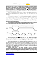
8µs (depends on the VDP command phase and operation requested). At CPU
clock speed of 3.58Mhz, 8µs equals to 28.5 T-cycles. To compare, one NOP
command takes 4 T-cycles, two EX (SP),HL command takes 38 cycles.
Therefore, increasing GR8BIT system clock frequency decreases length of
T-Cycle, and thus effective time dedicated for VDP data sampling and processing,
and at some critical value VDP stops working correctly. First it exhibits as small
artifacts on the screen, and as speed increases makes machine stop working
properly.
With GR8BIT you have flexibility to adjust length of the active phase of the
control signal using its slowdown circuit, but it has limitation of 15 additional wait
states, and does not allow lengthening time of signal inactivity.
Option #1: varying GR8BIT global speed with CPU board’s crystal
This option allows to slightly increase the processing speed of the machine.
No major hardware/design modifications are required. Here’re the steps to
achieve the results:
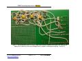
1. De-solder video board’s SMD jumper SJ1 to stop VDP supplying system
clock from its CPUCLK output. Note that VDPCLK will still be present on
the GR8BUS and can be used as a reference or source clock for your
devices;
2. Ensure SJ2 of the video board is soldered so that every VDP access would
activate slowdown circuit and you are able to tune number of VDP waitstates;
3. Ensure SJ1 and SJ7 are soldered on the CPU board, supplying clock signal
from XTAL1-based circuit to the GR8BUS as well as to the CPU;
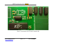
4. Solder CPU board’s clock circuit components: socket for IC1, R1, C1 and
C2, and R2’
5. Solder 3.579545Mhz crystal as XTAL1 (supplied within GR8BOX);
6. Put IC1 in (supplied within your GR8BOX), install CPU board into GR8BIT,
and start it to ensure that it works.
The drawback of this implementation that global clock frequency changes,
leading to changed pitch of PSG and SCC music.
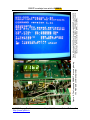
Your homework: try different crystals to see at which its nominal you notice
artifacts on the screen/GR8BIT does not start, varying number of wait-states
inserted using SW1 main board’s switch. Also ensure that this switch has position
#5 turned off (for modified slowdown circuit – turned on), and position #6
turned on (so that additional wait-states would apply also to PPI and RTC access
cycles).
© 2012 Eugeny Brychkov
http://www.gr8bit.ru
Page 3 / 17
Status: Released