1
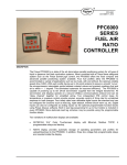
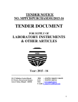
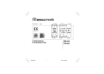
170.IU0.TMS.000
4.3-99/D
r USER MANUAL
TMS
INDEX
MOUNTING REQUIREMENTS .......................... 1
DIMENSIONS AND PANEL CUT OUT ............... 2
WIRING GUIDE LINES ....................................... 3
PRELIMINARY HARDWARE SETTINGS ........... 8
CONFIGURATION PROCEDURE ...................... 9
OPERATIVE MODE .......................................... 14
SMART function ........................................ 14
Output power OFF ..................................... 15
Heater break down alarm .......................... 15
Direct access to the set point .................... 16
Lamp test ................................................... 16
OPERATIVE PARAMETERS ............................ 16
ERROR MESSAGES ........................................ 19
GENERAL INFORMATIONS ............................ 21
DEFAULT PARAMETERS ............................... A.1
I
5) Make sure you cannot move the case within
the cut out otherwise you do not have a NEMA
4X/IP65 protection.
MOUNTING REQUIREMENTS
Select a mounting location having the following
characteristics:
1) it should be easy accessible also on the rear
side.
2) there is no vibrations or impact
3) there are no corrosive gases (sulphuric gas,
ammonia, etc.).
4) there are no water or other fluid (i.e. condense)
5) the ambient temperature is in accordance with
the operative temperature of the instrument
(from 0 to 50 °C).
6) the relative humidity is in accordance with the
instrument specifications ( 20% to 85 % non
condensing).
The instrument can be mounted on a panel up to
15 mm thick with a square cutout of 45 x 92 mm.
For outline and cutout dimensions refer to Fig. 2.
The surface texture of the panel must be better
than 6,3 µmm.
The instrument is shipped with rubber panel
gasket (50 to 60 Sh).
To assure the IP65 and NEMA 4 protection, insert
the panel gasket between the instrument and the
panel as shown in fig. 1.
screw
bracket
panel
screw
While holding the instrument against the panel
proceed as follows:
1) insert the instrument through the panel gasket,
2) insert the instrument, with the panel gasket,
through the panel cut out,
3) while pressing the instrument firmly against the
panel, insert the mounting bracket and slide it
up to the end of the case,
4) with a screwdriver, turn the screws with a
torque between 0.3 and 0.4 Nm,
gasket
Fig. 1
GB
1
DIMENSIONS AND PANEL CUT OUT
Fig. 2
GB
2
A) MEASURING INPUT
NOTE: Any external components (like zener
barriers etc.) connected between sensor and
input terminals may cause errors in measurement
due to excessive and/or not balanced line
resistance or possible leakage currents.
WIRING GUIDELINES
Connections are to be made with the instrument
housing installed in its proper location.
THERMOCOUPLE INPUT
+ 1
_ 3
Shield
+ 1
Fig. 3.A TERMINAL BLOCK (for 100/240 V AC
models)
_ 3
Shield
Fig. 4 THERMOCOUPLE INPUT WIRING
NOTE:
1) Don’t run input wires together with power cables.
2) For TC wiring use proper compensating cable
preferably shielded
3) If shielded cable is used, it should be grounded
at one point only.
Fig. 3.B TERMINAL BLOCK (for 24 V AC/DC
models)
GB
3
B) CURRENT TRANSFORMER INPUT
RTD INPUT
RTD
RTD
6
7
Current
transformer
4
3
1
4
3
1
Load
Fig. 5
RTD INPUT WIRING
NOTE:
1) Don’t run input wires together with power cables.
2) Pay attention to the line resistance; a high line
resistance (higher than 20 Ω/wire) may cause
measurement errors.
3) If shielded cable is used, it should be grounded
at one point only.
4) The resistance of the 3 wires must be the
same.
GB
Fig. 6
CURRENT TRANSFORMER INPUT
WIRING
Note:
1) The input impedance is equal to 10 Ω.
2) the maximum input current is equal to 50 mA
(50 / 60 Hz).
4
3) Use copper conductors only.
4) Don’t run input wires together with power cables.
5) Relay output and SSR drive output are both
available. When a relay output is desired it is
necessary to enable the SSR output and
viceversa (see chapter "Preliminary hardware
settings").
C) RELAY OUTPUTS
AL2/HBD
(OUT 3)
10
11
AL1/COOL
(OUT 2)
C - OUT 3
NO - OUT 3
NO/NC
[see Fig.11 (J303)] OUT 2
The following recommendations avoid serious
problems which may occur, when using relay
output for driving inductive loads.
16
17
C - OUT 2
INDUCTIVE LOADS
High voltage transients may occur when switching
inductive loads.
Through the internal contacts these transients
may introduce disturbances which can affect the
performance of the instrument.
The internal protection (varistor) assures a correct
protection up to 0.5 A of inductive component but
the OUT 1 NC contact and out 3 are not
protected.
The same problem may occur when a switch is
used in series with the internal contacts as shown
in Fig. 8.
C
OUT 1
20
NO
21
NC
22
Fig. 7
RELAY OUTPUT WIRINGS
The output 2 and the NO contact of the output 1 are
protected, by varistor, from inductive load with an
inductive component up to 0,5 A.
The rating of the out 1 contact is equal to 3A/250
V AC on resistive load.
The rating of the out 2 and 3 contacts is equal to
2A/250 V AC on resistive load.
The number of operations is 1 x 10⁵ at specified
rating.
NOTES:
1) To avoid electric shock, connect power line at
the end of the wiring procedure.
2) For power connections use No 16 AWG or larger
wires rated for at last 75 °C.
GB
Fig. 8 EXTERNAL SWITCH IN SERIES WITH
THE INTERNAL CONTACT
5
In these cases it is recommended to install an
additional RC network across the external contact
(or close to the non protected contact of the
instrument) as shown in Fig. 8.
The capacity (C) and resistive (R) values are
shown in the following table.
LOAD
(mA)
C
(µF)
R
(Ω)
P.
(W)
OPERATING
VOLTAGE
<40 mA 0.047 100
<150 mA 0.1
22
<0.5 A
0.33 47
1/2
2
2
260 V AC
260 V AC
260 V AC
D) LOGIC OUTPUT FOR SSR DRIVE
_
18
OUT 1
19
+
_
+
Solid state relay
_
14
OUT 2
(AL1/Cool.)
The cable involved in relay output wiring must be
as far away as possible from input or communication cables.
15
+
_
+
Solid state relay
Fig. 9
SSR DRIVE OUTPUT WIRING.
These are time proportioning outputs.
Logic level 0: Vout < 0.5 V DC.
Logic level 1:
- 14 V + 20 % @ 20 mA
- 24 V + 20 % @ 1 mA.
Maximum current = 20 mA.
NOTES:
1) These outputs are not isolated.
A double or reinforced isolation between instrument output and power supply must be assured
by the external solid state relay.
2) Relay output and SSR drive output are both
available. When a SSR output is desired it is
necessary to enable the relay output and
viceversa (see chapter "Preliminary hardware
settings").
GB
6
E) POWER SUPPLY
- It shall be in close proximity to the equipment
and within easy reach of the operator;
- it shall be marked as the disconnecting
device for the equipment.
NOTE: a single switch or circuit-breaker can drive
more than one instrument.
9) When a neutral line is present, connect it to
terminal 12.
N
R (S,T)
N
13
Power line
from 100 V to 240 V AC (50/60Hz)
or 24 V AC/DC
R (S,T)
12
Fig. 10 POWER LINE WIRING
NOTE:
1) Before connecting the instrument to the power
line, make sure that line voltage corresponds
to the description on the identification label.
2) To avoid electric shock, connect power line at
the end of the wiring procedure.
3) For supply connections use No 16 AWG or larger
wires rated for at last 75 °C.
4) Use copper conductors only.
5) Don’t run input wires together with power cables.
6) For 24 V AC/DC power supply, the input polarity
is a do not care condition.
7) The power supply input has no fuse protection.
Please, provide a fuse type T, 1 A, 250 V
externally.
When fuse is damaged, it is advisable to verify
the power supply circuit, so that it is necessary to
send back the instrument to your supplier.
8) The safety requirements for Permanently
Connected Equipment say:
- a switch or circuit-breaker shall be included in
the building installation;
GB
7
OPEN INPUT CIRCUIT
PRELIMINARY HARDWARE
SETTINGS
These device are capable to detect leads break
for TC and RTD inputs. For RTD input it shows
this status as an overrange condition.
For thermocouple input only, it is possible, to
select the overrange indication (standard) by
closing CH2 and opening SH2 or underrange
indication by closing SH2 and opening CH2.
SH2 and CH2 are located on the soldering side of
the CPU card (see fig.12).
1) Remove the instrument from its case.
2) For out 1 and 2 it is possible to select the
desired output type by setting the J304 and J305
jumpers.
J304 (AL1, Cool.)
1-2 = SSR 2-3 = Relay
J305 (OUT 1)
1-2 = SSR 2-3 = Relay
3) For out 2 it is possible to select the used relay
contact (NO or NC) by setting J303 jumper.
J303 (AL1, Cool.) 1-2 = Out NO
2-3 = Out NC
Note : J303 is a soldering jumper and it is located
on the soldering side of the card.
CH2
SH2
1
J 303
1
3
J304
J305
J3 0 5
PZ22
R 3 01
1
R 3 03
1
4
3
Q 304
1
2
1
R 312
Q 303
L 30 1
C 301
K 3 01
PZ20
R 30 2
5
R 304
PZ21
L 30 4
J3 04
C 3 05
Q 301
4
3
C3
C312
PZ17
C 309
R30 9
C 3 08
7
+
1
C 306
I
05
B
4
TR301
J302
D3
3
U 30 1
-
+
C 3 07
C 310
PZ15
C 314
PZ16
L3 03
C
E
1 Q 302
R 310
3
2
PZ13
R 30 6
D307
R308
R 307
D306
D301
C 30 2
I
L 30 2
04
C 303
D304
U 302
R 3 05
C 31 1
D310
PZ18
2
PZ14
1
Q305
C 313
2
K 30 2
R314
R3 1 1
3
PZ19
5
J303
R 3 13
D302
Fig. 12
J301
1
1
4
D308
X Y 00
L305
PZ12
Y3 0 1
Fig 11
GB
8
3) Re-insert the instrument..
4) Switch the instrument “ON”.
The display will show COnF.
NOTE : If “CAL” indication is displayed, press
immediately the s push-button to return to the
configuration procedure.
5) Push the FUNC push-button.
The instrument will show on the lower display
the parameter code and on the upper display
the actual parameter value.
GENERAL NOTES for configuration.
FUNC =
This will memorize the new value of
the selected parameter and go to the
next parameter (increasing order).
SMRT = This will scroll back the parameters
without memorization of the new value.
s
= This will increase the value of the
selected parameter
t
= This will decrease the value of the
selected parameter.
P1 - Input type and standard range
0 = TC type L
range 0 / +800 °C
1 = TC type J
range 0 / +800 °C
2 = TC type K
range 0 / +999 °C
3 = TC type N
range 0 / +999 °C
4 = RTD type Pt 100 range -199 / +500 °C
5 = RTD type Pt 100 range -19.9 /+99.9 °C
6 = TC type T
range 0 / +400 °C
8 = TC type L
range 0 / +999 °F
9 = TC type J
range 0 / +999 °F
10 = TC type K
range 0 / +999 °F
11 = TC type N
range 0 / +999 °F
12 = RTD type Pt 100 range -199 / +999 °F
13 = TC type T
range 0 / +752 °F
CONFIGURATION PROCEDURE
1) Remove the instrument from its case.
2) Set the internal switch V2 in open condition
P2 = Initial scale value
Not present when P1 = 5
Initial scale value used by the PID algorithm to
calculate the input span.
P2 is programmable within the input span
selected by P1.
When P2 has been modified, the instrument
assignes to the rL parameter the new P2 value.
Fig.13
V2
GB
9
P3 = Full scale value
Not present when P1 = 5
Full scale value used by the PID algorithm to
calculate the input span.
P3 is programmable within the input span
selected by P1.
When P3 has been modified, the instrument
assignes to the rH parameter the new P3 value.
NOTE: the minimum input span (P3 - P2) is
- 300 °C or 600 °F for TC input
- 100 °C or 200 °F for RTD input.
P4 = Output configuration
H = heating
HC = heating/cooling
P5 = Main output type
rEL = Relay output.
SSr = SSR output.
NOTE:
Setting P5 = rEL,
the C parameter will be
automatically set to 20 s.
Setting P5=SSr,
the C parameter will be
automatically set to 2 s.
P6 = Cooling output type
Available only when P4 = HC
AIr = air
OIL = oil
H2O = water
NOTE:
Setting P6 = Air,
the C2 parameter will be
automatically set to 10 s
and rC parameter will be
set to 1.00.
Setting P6=OiL,
the C2 parameter will be automatically set to 4 s and rC
parameter will be set to 0.80.
GB 10
Setting P6=H2O,
the C2 parameter will be automatically set to 2 s and rC
parameter will be set to 0.40.
P7 = Alarm 1
Available only when P4 = H.
0 = Not provided
1 = Process alarm
2 = Band alarm
3 = Deviation alarm
P8 = Alarm 1 operative mode
Available only when P7 is different from 0 and
P4 = H.
H.A = high alarm (outside band) with automatic
reset
L.A = low alarm (inside band) with automatic reset
H.L= high alarm (outside band) with manual reset
L.L= low alarm (inside band) with manual reset
P9 = Stand by (mask) of the alarm 1
Available only when P7 is different from 0 and
P4 = H.
OFF = stand by (mask) disabled
ON = stand by (mask) enabled
NOTE: the alarm stand by function allows to
disable the alarm indication at instrument start up
or, for band and deviation alarms, after a set point
modification.
The alarm will be automatically reactivated when
the initial alarm condition disappears.
P10 = Alarm 2
0 = Not provided
1 = Process alarm
2 = Band alarm
3 = Deviation alarm
Alarm 2 and HBD functions are in OR condition
on the output 3 (see P16 parameter).
P11 = Alarm 2 operative mode and reset of the
HBD alarm.
Available only when P10 is different from 0 or P16
is different from OFF.
H.A = high alarm (outside band) with
automatic reset
L.A = low alarm (inside band) with automatic reset
H.L= high alarm (outside band) with manual reset
L.AL= low alarm (inside band) with manual reset
NOTE: The HBD alarm is a low alarm but it
assumes the same reset type selected for
alarm 2.
P12 = Stand by (mask) of the alarm 2
Available only when P10 is different from 0.
OFF = stand by (mask) disabled
ON = stand by (mask) enabled
For other details see P9 parameter.
P13 = Type of OFFSET applied to the
measured value
P13 = 0
the OFFSET (P14) is
constant all over the range.
P13 different from 0P13 is the application point of
the OFFSET selected by P14
parameter.
NOTE: the P13 and P14 parameters do not
modify the measuring or read-out limits of the
instrument so that when one of this limit has been
exceeded, the instrument will show an out of
range condition.
GB 11
P14 = OFFSET value
When P13 = 0,
P 14 is programmable, in
engineering units, from -20% to
+ 20% of the input span (see
P1).
When P13 ≠ 0
P14 is programmable, in
engineering units, from -20% to
+ 20% of the P13 value.
NOTE: the P14 parameter can not be set lower
than -199 units.
Readout.
Real
curve
Readout.
Real
curve
P14
P14
Adjusted
curve
Input
P13 = 0
Adjusted
curve
P13
Input
P15 = Threshold of the “Soft Start” function.
Threshold value, in engineering units, used by the
instrument for automatic enabling of the "soft
start" function (timed output power limiting).
At instrument start up, if the measured value is
lower than the programmed threshold value, the
instrument will automatically enable the output
power limiter (see OLH parameter) and it
maintains this limit for a time programmed by tOL
parameter.
At instrument start up, if the tOL parameter is
equal to "InF", the P15 setting has no effect.
P16 = Measure of the current consumed by
the load driven by the main output
(HBD)
OFF = measure disabled
n.O. = measure enabled during the ON period
(logic status 1 for SSR output or contact
NO for relay output)
n.C. = measure enabled during the OFF period
(logic status 0 for SSR output or contact
NC for relay output)
P17 = Full scale of the current transformer.
Available only when P16 is different from OFF.
10 = 10 A (resolution: 0.1 A)
25 = 25 A (resolution: 1 A)
50 = 50 A (resolution: 1 A)
100 = 100 A (resolution: 1 A)
P18 = Safety lock
0 = device unlocked. All the parameters can be
modified
1 = device locked. No one parameters can be
modified exception made for SP.
From 2 to 499 = during operative mode, SP
parameter can be modified and
this number allows to enable/
disable the modification of all the
other parameters.
From 500 to 999 = SP, A1 and A2 parameters
can be modified and this number
allows to enable/disable the
modification of all the other
parameters.
NOTE: After FUNC push-button pressure it will be
impossible to display this value again. If you don't
remember the old key, set a new value.
GB 12
The configuration procedure is completed and the
" on both displays.
instrument will show "
When it is desired to end the configuration
procedure push the FUNC push-button; the
display will show "COnF".
-.-.-.
When it is desired to access to the advanced
configuration parameter, proceed as follows:
1) using s and t push-button set the 217 code.
2) push the FN push-button; the instrument will
start the auxiliary configuration procedure and
it will show the following additional parameters.
P19 - Main output action
Available only when P4 = H.
r = Reverse (heating)
d = direct (cooling)
Note : when P4 = HC, this parameter is
equal to "r".
Reverse
Direct
Input
Input
t
Output
t
Output
t
t
P21 - Alarm 1 output action
Available only when P7 is different from 0 and P4
is equal to H.
r = reverse (relay de-energized in alarm
condition).
d = Direct (relay energized in alarm condition)
P22 - Alarm 2 output action
Available only when P10 is different from 0 and
P16 is different from "OFF".
r = reverse (relay de-energized in alarm
condition).
d = Direct (relay energized in alarm condition)
P23 - Automatic modification of the "relative
cooling gain"
Available only when P4=HC.
OFF = The SMART function will NOT modify
the "relative cooling gain" parameter
value.
ON = The SMART function will modify the
"relative cooling gain" parameter value.
P24 - Control output maximum rate of rise
This parameter allows to set the maximum rate of
rise of the control output.
It is programmable from 1 to 10 % of the output
signal per second.
Setting a value greater then 10%/s the upper
display will blank and no limit is applied.
P25 - Display of the protect parameter
enabling/disabling.
Available only when P18 is different from 0.
OFF = protected parameter cannot be displayed
ON = protected parameter can be displayed
P26 - SMART function enabling/ disabling
0=
The SMART function is disabled
1=
The SMART function enabling/disabling
is NOT protected by the safety key.
2 =
The SMART function enabling/disabling
is protected by the safety key.
GB 13
P27 - Maximum value of the proportional band
settable by the SMART function
Available only when P26 is different from 0.
This parameter may be programmed from P28 or
P29 value to 99.9.
P28 - Minimum value of the proportional band
settable by the SMART function
Available only when P4=H and P26 is different
from 0.
This parameter may be programmed from 1.0 %
to P27 value.
P29 - Minimum value of the proportional band
settable by the SMART function in heating/
cooling control only
Available only when P4=HC and P26 is different
from 0.
This parameter may be programmed from 1.5 %
to P27 value.
P30 - Minimum value of integral time settable
by SMART function.
Available only when P26 is different from 0.
This parameter may be programmed from 00.1
(mm.s) to 02.0 (mm.s).
P31 - Extension of the anti-reset-wind up
Range: from -30 to +30 % of the proportional
band.
NOTE: a positive value increases the high limit of
the anti-reset-wind up (over set point) while a
negative value decreases the low limit of the antireset-wind up (under set point).
The auxiliary configuration is finished and the
instrument will show "CnF" on the upper display.
OPERATIVE MODE
SMART function
1) Remove the instrument from its case.
2) Set the V2 jumper (see fig. 13) in close
condition.
3) Re-insert the instrument.
4) Switch on the instrument.
The SMART algorithm is a NEW self-tuning
function of the instrument. It is used by the
instrument to calculate and set automatically the
control parameters.
The SMART algorithm may be ever operative; in
this case it will adapt continuously the control
parameter in order to perform the best control
action.
To start "SMART" function, depress the SMRT
push-button for more than 1.5 seconds when the
instrument is in NORMAL DISPLAY MODE, the
SMRT indicator will start blinking or lighting
according to the special function performing.
When it is desired to disable the SMART function,
push the SMRT push-button again, the SMRT
indicator will turn to OFF.
NOTES:
1) During the SMART function operation, the
relative cooling gain (if present) is limited within
the following ranges:
Cooling element
range
Air
0.85 to 1.00
OIL
0.80 to 0.90
0.30 to 0.60
H2O
2) The SMART function use a derivative action
equal to 1/4 of the integral action.
3) The limits of the proportional band and of the
integral time settable by the SMART function
are programmed by P27, P28, P29 and P30
parameter.
4) The enabling/disabling of the SMART function
may be under safety key protection.
5) When SMART function is enabled, it is
impossible to modify the Pb, ti and td
parameter; for rC parameter see P23
parameter.
The upper display will show the measured value
while the lower display will show the programmed
set point (we define this display condition as
“normal display mode”).
Note: When a ramp is applied to the set point value
(see rP parameter), the displayed set point
value may be different from the operative set
point.
When the HBD function is configured, the control
output is enabled and the instrument is in normal
display mode, pushing the s push-button the
lower display will show the current, followed by
the "A" symbol, consumed by the load driven by
the main output.
NOTE: the time out has no effect on this
indication.
When it is desired to come back to the normal
display mode, push the s push-button again.
GB 14
OUTPUT POWER OFF
The TMS allows to turn OFF manually the output
signal in order to stop the control (the instrument
will operate as an indicator only).
To turn OFF the output signal proceed as follows:
1) push and maintain the pressure on the s
push-button
2) push FUNC push-button.
3) Maintaining the pressure on both push-buttons
for more than 3 seconds; the lower display will
show "OFF" and the output signal will be
inhibited.
When it is desired to come back to the normal
control, repeat the actions 1, 2 and 3; the
instrument goes automatically to the NORMAL
DISPLAY MODE.
NOTE: 1)The instrument memorizes the output
status.
2) If the output is turned OFF when the
SMART function was performing the first
part of the algorithm (LED SMRT is
flashing), the SMART function will be
aborted and when the instrument comes
back to the normal control, the SMART
function will be disabled.
If the output is turned OFF when the
SMART function was performing the
adaptive part of the algorithm (LED
SMRT is lit), the SMART function will be
stopped and, when the instrument
comes back to the normal control, the
smart function also will be activated.
GB 15
HEATER BREAK DOWN ALARM
This alarm allows to verify, continuously, the
current consumed by the load driven by the main
output and generates an alarm condition when
this current is lower than a programmable
threshold.
To display the main load consumption, push the
s push-button when the instrument is in
NORMAL DISPLAY MODE.
The upper display will show the measured value
while the lower display will show the main load
consumption (in Ampere) followed by the
engineering unit (A).
To come back to the normal display mode, push
the s push-button.
When an alarm condition is detected, the LED
AL2/HB will be flashing and the relay of the out 3
(alarm 2 OR heater break down alarm) will be
activated.
DIRECT ACCESS TO THE SET POINT
MODIFICATION
The instrument allows to modify the set point
value without to use the FUNC push-button.
When a rapid set point modification is required,
proceed as follows:
1) Pushing, for more than 3 seconds, the s or
t push-button; the set point value, shown on
the lower display, will start to change.
2) Using the s and t push-buttons, it is
possible to set the desired value.
3) When the desired value is reached, do not
push any push-button for more than 3
seconds, the new set point will become
operative after 3 seconds from the last pushbutton pressure.
If, during this procedure, it is desired to lose the
new value, push the FUNC push-button; the
instrument automatically returns to the normal
display mode without to memorize the new set
point.
LAMP TEST
When it is desired to verify the display efficiency,
push t and FUNC push-buttons. The instrument
will turn ON, with a 50 % duty cycle, all the LED
of the display (we define this function "LAMP
TEST").
No time out is applied to the LAMP TEST.
When it is desired to come back to the normal
display mode, push t and FUNC push-buttons
again.
No other keyboard function is available during
LAMP TEST.
GB 16
OPERATIVE PARAMETERS
Operative parameter modification
Push the FUNC push-button, the lower display
will show the code while the upper display will
show the value or the status (ON or OFF) of the
selected parameter.
By s or t push-button it is possible to set the
desired value or the desired status.
Pushing the FUNC push-button, the instrument
memorizes the new value (or the new status) and
goes to the next parameter.
A pressure of the SMRT push-button allows to come
back to the previous parameter without to memorize
the new set of the actual parameter.
Some parameters may be not visualized according
to the specific instrument configuration.
NOTE: 1)
If, during operative parameter
modification, no push-button is
pressed for more than 10 seconds,
the instrument reverts automatically
to the “normal display mode” without
to memorize the last parameter
setting.
2) The instrument do not display all
parameter but it select the
parameter in accordance with:
a) the instrument configuration
b) P25 setting
c) the proportional band setting.
Param.Description
SP
n.rS
nnn
A1
A2
H1
Main set point
Range: from rL to rH.
Manual reset of the alarms
This parameter is available only when one
alarm with manual reset has been
programmed.
Set ON and push the FUNC push-button
to reset the alarms.
Software key for parameter protection.
This parameter is skipped if P18 = 0 or 1.
The instrument will shows the safety key
status:
ON = the instrument is in LOCK condition
OFF = the instrument is in UNLOCK
condition
When it is desired to switch from LOCK to
UNLOCK condition, set a value equal to
P18 parameter
When it is desired to switch from UNLOCK
to LOCK condition, set a value different
from P18 parameter.
Alarm 1 threshold value
This parameters is present if the alarm 1
is configured only.
Ranges:
- From P2 to P3 for process alarm.
- From 0 to 500 units for band alarm.
- From -199 to 500 units for deviation
alarm.
Alarm 2 threshold value
For other details see A1 parameter.
Alarm 1 hysteresis
This parameters is present if the alarm 1
is configured only.
Range: From 0.1% to 10.0% of the input
span or 1 LSD.
GB 17
H2
Pb
HS
ti
td
Note: If the hysteresis of a band alarm is
larger than the alarm band, the instrument
will use an hysteresis value equal to the
programmed band minus 1 digit.
Alarm 2 hysteresis
For other details see H1 parameter.
Proportional band.
Range: from 1.0 % to 99.9 % of span for
heating output.
From 1.5 % to 99.9 % of span for heating/
cooling output.
When Pb parameter is set to 0, the
instrument performs an ON-OFF control;
the ti, td, IP, C, C2, rC, OLP, OLH and
tOL parameters are skipped and SMART
function is disabled.
Note: When SMART is enabled, the Pb
parameter range is limited by P27, P28 and
P29 parameters.
Hysteresis for ON/OFF control action
It is available only when Pb=0.
Range: from 0.1% to 10.0% of the input
span.
Integral time
"ti" is skipped if Pb=0 (ON/OFF action).
Range: from 00.1 to 20.0 [mm.ss]. Above
this value the display blanks and integral
action is excluded
Note: When SMART is enabled, the minimum value of the integral time is limited by
P30 parameter.
Derivative time
"td" is skipped if Pb=0 (ON/OFF action).
Range: from 0.01 to 9.59 m.ss. Setting the
0 value the derivative action is excluded.
Note: When SMART is enabled the td
value will be equal to 1/4 of the integral
time.
IP
C
C2
rC
OLP
rL
rH
Integral pre-load
"IP" is skipped if Pb=0 (ON/OFF action).
Ranges:
- from 0 to 100 % when P4 = H
- from -100 to 100 % when P4 = HC
Output 1 cycle time
C is available if Pb parameter is different
from 0 only.
Range: from 1 to 200 s.
Output 2 cycle time
C2 is available only if P4 = "HC" and Pb is
different from 0 only.
Range: from 1 to 200 s.
Relative Cooling gain .
"rC" is skipped if Pb=0 (ON/OFF action)
or P4 = H.
Range: from 0.20 to 1.00
Note: When SMART function is enabled,
the "rC" parameter is limited in accordance to the selected coolant:
- from 0.85 to 1.00 when P6 = AIr
- from 0.80 to 0.90 when P6 = OIL
- from 0.30 to 0.60 when P6 = H2O
Dead band/Overlap between H/C
outputs
"OLP" is skipped if Pb=0 (ON/OFF action)
or P4 = H.
A negative OLAP value shows a dead
band while a positive value shows an
overlap.
Range: from -20 to 50.
Set point low limit
Range: from min. range value (P2) to rH.
Note: When P2 has been modified, rL will
be realigned to it.
Set point high limit
Range: From rL to full scale value (P3).
Note: When P3 has been modified, rH will
be realigned to it.
GB 18
rP
OLH
tOL
Hbd
Ramp applied to the set point changes
Range: from 1 to 100 digit/min.
Above this value the display shows "inf"
and the transfer will be a step transfer.
Control output high limit
"OLH" is skipped if Pb=0 (ON/OFF action).
Range:
- from 0 to 100 % when P4 = H
- from -100 to 100 % when P4 = HC
Time duration of the output power
limiter
"tOL" is skipped if Pb=0 (ON/OFF action).
Range: from 1 to 100 min.
Above this value the display shows "inf"
and the limit will be ever enabled.
Note: The tOL can be modified but the
new value will become operative only at
the next instrument start up.
Threshold of the heater break down
alarm
"Hbd" is available only when P16 is
different from OFF.
Range: within the current transformer
range (see P17).
ERROR MESSAGES
OVERRANGE, UNDERRANGE AND BURNOUT
INDICATIONS
The instrument shows the OVERRANGE
condition with the following indication on the
upper display:
OFF and OUT 2 turn ON.
- The instrument is set for one output only and an
UNDERRANGE is detected, the OUT 1 turns
ON (if reverse action) or OFF (if direct action).
- The instrument is set for heating/cooling action
and an UNDERRANGE is detected, OUT 1
turns ON and OUT 2 turns OFF.
ERRORS
Diagnostics are made at instrument switch-on
and during normal mode of operation.
If a fault condition (error) is detected, the lower
display will show the message "Er" while the
upper display shows the relative error code.
The instrument shows the UNDERRANGE
condition with the following indication on the
upper display:
The sensor leads break can be signalled as:
- for TC input : OVERRANGE or
UNDERRANGE selected by a
solder jumper (see Fig. 12).
- for RTD input : OVERRANGE
Sensor leads short circuit detection:
On RTD input, a special test is provided to signal
OVERRANGE when input resistance is less than
15 ohm (Short circuit sensor detection).
NOTE: When:
- The instrument is set for one output only and an
OVERRANGE is detected, the OUT 1 turns
OFF (if reverse action) or ON (if direct action).
- The instrument is set for heating/cooling action
and an OVERRANGE is detected, OUT 1 turns
GB 19
ERROR LIST
100
Write EEPROM error.
150
General hardware error on the CPU card.
200
Tentative to write on protected memory.
201 - 2xx Configuration parameter error. The two
less significant digit’s shown the number
of the wrong parameter (ex. 209 Err show
an Error on P9 parameter)
301
RTD input calibration data error
305
TC input calibration data error
307
RJ calibration data error
310
Current transformer input calibration data
error
400
Control parameters error
500
Auto-zero error.
502
RJ error.
510
Error during calibration procedure.
NOTE
1) When a configuration parameter error is
detected, it is sufficient to repeat the configuration procedure of the specify parameter.
2) If an error 400 is detected, push contemporarily the t and s push-buttons for loading the
default parameters then repeat control
parameter setting.
3) For all the other errors, contact your supplier.
GB 20
GENERAL INFORMATIONS
GENERAL SPECIFICATIONS
Case: PC-ABS black color; self-extinguishing degree: V-0 according to UL 94.
Front protection - designed and tested for IP 65 (*)
and NEMA 4X (*) for indoor locations (when panel
gasket is installed).
(*) Test were performed in accordance with CEI 701 and NEMA 250-1991 STD.
Installation: panel mounting by means of mounting
bracket. Instrument removable from case.
Rear terminal block: 21 screw terminals ( screw
M3, for cables from φ 0.25 to φ 2.5 mm2 or from
AWG 22 to AWG 14 ) with connection diagrams
and safety rear cover.
Dimensions: 48 x 96 mm, depth 89 mm (DIN
43700).
Weight: 600 g.
Power supply:
- 100V to 240V AC 50/60Hz (-15% to + 10% of
the nominal value).
- 24 V AC/DC (+ 10 % of the nominal value).
Power consumption: 6 VA max.
Insulation resistance: > 100 MΩ according to
IEC 1010-1.
Dielectric strength: 1500 V rms according to IEC
1010-1.
Sampling time: 500 ms.
Resolution: 30000 counts.
Accuracy (@ 25 °C): +0.2% of the input span +1 °C.
Common mode rejection: 120 dB at 50/60 Hz.
Normal mode rejection: 60 dB at 50/60 Hz.
Electromagnetic compatibility and safety
requirements: This instrument is marked CE.
Therefore, it is conforming to council directives
89/336/EEC (reference harmonized standard
EN 50081-2 and EN 50082-2)and to council
directives 73/23/EEC and 93/68/EEC
GB 21
(reference harmonized standard EN 61010-1).
Installation category: II
Temperature drift: (RJ excluded)
< 400 ppm/°C for RTD input with -19.9/99.9 °C
range and TC type T.
< 200 ppm/°C for all the other ranges.
Operative temperature: from 0 to 50 °C.
Storage temperature : -20 to +70 °C
Humidity: from 20 % to 85% RH, non condensing.
Protections:
1) WATCH DOG circuit for automatic restart.
2) DIP SWITCH for protection against tampering
of configuration and calibration parameters.
INPUTS
A) THERMOCOUPLE
Type: L, J, K, N, T programmable by front pushbuttons.
Line resistance: max. 100 Ω with error <+0.1%
of the input span.
Burnout: Up or down scale selectable by
soldering jumpers.
Reference junction: automatic compensation
from 0 to +50 °C.
Reference junction drift: 0.1 °C/°C.
Input impedance: > 1 MΩ
Calibration: according to IEC 584-1 and DIN
43710 - 1977 (TC L)
STANDARD RANGE TABLE
TC
Type
L
J
K
T
N
Measuring ranges
0/
0/
0/
0/
0/
+ 800
+ 800
+ 999
+ 400
+ 999
°C
°C
°C
°C
°C
0 / + 999
0 / + 999
0 / + 999
0 / + 752
0 / + 999
°F
°F
°F
°F
°F
B) RTD (Resistance Temperature Detector)
Type: Pt 100 3 wires connection.
Current: 135 µA.
Line resistance: automatic compensation up to
20 Ω/wire with :
- error <+0.1% of the input span for range -19.9 a
99.9 °C.
- not measurable error for the other ranges.
Engineering units: °C or °F programmable.
Burnout: up scale. NOTE: a special test is
provided to signal OVERRANGE when input
resistance is less than 15 Ω.
Calibration: according to DIN 43760.
STANDARD RANGE TABLE
RTD
Measuring range
Type
RTD Pt 100
-199 - +500 °C
-199 - +999 °F
RTD Pt 100
-19.9 - +99.9 °C
-----
C) CURRENT TRANSFORMER INPUT
Input current: 50 mA AC.
Read-out: selectable among 10, 25, 50 or 100 A.
Resolution:
- 0.1 A for 10 A range.
- 1 A for all the other ranges.
Active period:
- for relay output: NO or NC programmable
- for SSR drive output: logic level 1 or 0
programmable.
Minimum time duration of the active period:
50 ms.
GB 22
CONTROL ACTIONS
Control actions: PID + SMART
Proportional band: from 1.0 % (for heating
action) or 1.5 % (for heating and cooling action)
to 99.9 % of the input span.
Setting Pb = 0 an ON/OFF control is performed.
Hysteresis (for ON/OFF control action): from 0.1
% to 10.0 % of the input span.
Integral time: from 10 seconds to 20 minutes;
resolution 10 second. Setting a value upper than
20 minutes the integral action will be excluded.
Derivative time: from 0 to 9' 59''.
Integral preload:
- from 0 to 100% for one control output.
- from -100 to 100% for two control outputs
Main output cycle time: from 1 to 200 s.
Cooling cycle time: from 1 to 200 s
Relative cooling gain: from 0.20 to 1.00
NOTE: the Pb, ti, td and rCG parameter may be
limited when the SMART function is enabled.
Overlapping/dead band: from - 20 % to 50 %
CONTROL OUTPUTS
Type: time proportioning
Output updating time: 500 ms.
Output resolution: 1% of the output span.
Action: direct or reverse programmable.
Output power limiter:
- from 0.0 to 100.0 % for one control output.
- from -100.0 to +100.0% for two control outputs
This function may be operative at instrument power
up for a programmable time (to avoid thermal shock
or to pre-heat the plant).
OUTPUT 1
a) Relay output with SPDT contact;
contact rating 3A / 250 V AC on resistive load.
b) Logic voltage for SSR drive.
Logic status 1: 24 V +20% @ 1 mA.
14 V +20% @ 20 mA
Logic status 0: <0.5 V
Output action: direct/reverse programmable.
The relay or SSR output selection is made by
internal jumper and configuration parameter.
OUTPUT 2 - cooling / alarm 1
a) Relay output with SPST contact;
contact rating 2A / 250 V AC on resistive load
b) Logic voltage for SSR drive.
Logic status 1: 24 V +20% @ 1 mA.
14 V +20% @ 20 mA
Logic status 0: <0.5 V
The relay or SSR output selection is made by
internal jumper and configuration parameter.
ALARMS
The instrument may accommodate up to 2
independent alarms.
The alarm 1 is a standard features of the
instrument while the alarm 2 is an option.
Each alarm can be programmed as follows:
Process alarm:
Operative mode: High or low programmable.
Threshold: Programmable in engineering units
within the input span (P3 - P2).
Band alarm
Operative mode: inside or outside band.
Threshold: programmable from 0 to 500 units.
GB 23
Deviation alarm
Operative mode: upper or lower the programmed
value.
Threshold: programmable from - 500 to +500
units.
Action: direct or reverse programmable
Threshold resolution: 1 digit.
Alarm hysteresis: programmable from 0.1 % to
10.0 % of the input span.
Alarm reset: automatic or manual programmable
Stand by (mask) alarm: Each alarm can be
programmed with or without mask function.
This function allows to delete not desired alarm
indication at instrument power up or after a set
point modification.
Alarm indications: the AL1/COOL LED lit when the
alarm 1 is in ON condition.
The AL2/HBD LED operate as follows:
HBD
AL2
LED
status status
AL2/HBD
0
0
OFF
0
1
ON
1
0
flashing at slow rate
1
1
Flashing at high rate
Alarm outputs:
1) Alarm 1 : relay output with SPST contact;
Contact rating 3A/250V AC on resistive load
2) Alarm 2 : relay output with SPST contact;
Contact rating 2A/250V AC on resistive load
NOTE: Alarm 2 and HBD alarm are in OR
condition on the output 2 relay.
HEATER BREAK DOWN ALARM
This alarm allows to verify, continuously, the
current consumed by the load driven by the main
output and to generate an alarm condition when
this current is lower than a programmable
threshold.
Resolution: 1 digit.
Alarm hysteresis: 1 % of the selected range.
Alarm indication: ’AL2 HB" LED flash when the
alarm is in ON condition.
SPECIAL FUNCTION
Output power OFF
This function allows to turn OFF manually the
output signal and to inhibit the control algorithm
and the alarm functions.
In this way the controlled element is turned OFF
and the instrument operate as an indicator.
When the control restart, the instrument operates
as follows:
- the integral action will be set to 0.
- the soft start function and alarm masking will be
reactivated.
LAMP TEST
This function allows to verify the correct LED
operativity.
GB 24
MAINTENANCE
1) REMOVE POWER FROM THE POWER
SUPPLY TERMINALS AND FROM RELAY
OUTPUT TERMINALS
2) Remove the instrument from case.
3) Using a vacuum cleaner or a compressed air
jet (max. 3 kg/cm2) remove all deposit of dust
and dirt which may be present on the louvers
and on the internal circuits trying to be careful
for not damage the electronic components.
4) To clean external plastic or rubber parts use
only a cloth moistened with:
- Ethyl Alcohol (pure or denatured) [C2H5OH]
or
- Isopropil Alcohol (pure or denatured)
[(CH3)2CHOH] or
- Water (H2O)
5) Verify that there are no loose terminals.
6) Before re-inserting the instrument in its case,
be sure that it is perfectly dry.
7) re-insert the instrument and turn it ON.
This means that the loading procedure has been
initiated. After about 3 seconds the loading
procedure is terminated and the instrument
reverts to NORMAL DISPLAY mode.
DEFAULT PARAMETERS
DEFAULT OPERATIVE PARAMETERS
The control parameters can be loaded with
predetermined default values. These data are the
typical values loaded in the instrument prior to
shipment from factory. To load the default values
proceed as follows:
The following is a list of the default operative
parameters loaded during the above procedure:
PARAMETER
a) The internal switch should be closed.
b) The SMART function should be disabled.
c) The upper display will show the process
variable while the lower display will show the
set point value or the current measure.
d) Held down t pushbutton and press s
pushbutton; the display will show:
SP
n.rS
nnn
A1, A2
H1, H2
Pb
hS
ti
td
IP
OFF
DFL
e) Within 10 seconds press s or t pushbutton.
The display will show:
C
On
C2
DFL
rC
g) Press FUNC pushbutton; the display will show:
OLP
rL
rH
rP
OLH
tOL
Hbd
L. d t.
A. 1
DEFAULT VALUE
= minimum range-value
= OFF
= OFF
= minimum range-value for
process alarms
0 for deviation or band alarms
= 0.1 %
= 4.0 %
= 0.5 %
= 04.0 (4 minutes)
= 1.00 (1 minute)
= 30 % for 1 control output
0 % for two control outputs
= 20 seconds for relay output
2 seconds for SSR output
= 10 seconds for P6 = AIr
4 seconds for P6 = OIL
2 seconds for P6 = H2O
= 1.00 for P6 = AIr
0.80 for P6 = OIL
0.40 for P6 = H2O
=0
= initial scale value
= full scale value
= infinite (step transfer)
= 100 %
= infinite
= 50 % of the full scale value.
DEFAULT CONFIGURATION
PARAMETERS
t b. 1
dFL
The configuration parameters can be loaded with
predetermined default values. These data are the
typical values loaded in the instrument prior to
shipment from factory. To load the default values
proceed as follows:
f) Press FUNC pushbutton; the display will show:
L. d t.
a) The internal switch (V2, see fig. 13) should
be open.
b) The upper display will show:
This means that the loading procedure has been
initiated. After about 3 seconds the loading
procedure is terminated and the instrument
reverts to visualization as in point b).
CnF
The following is a list of the default parameters
loaded during the above procedure:
c) Push the t pushbutton; the lower display will
show the firmware version.
PARAMETER
P1
P2
P3
P4
P5
P6
P7
P8
P9
P10
P11
P12
P13
P14
P15
P16
P17
P18
P19
CnF
A. 0 1
d) Maintaining the pressure on the t pushbutton
push the s pushbutton also.
The instrument will show
OFF
dFL
e) Press s pushbutton to select between table 1
(european) or table 2 (american) default
parameter set. The display will show:
A. 2
TABLE 1
1
0 °C
400 °C
H
rEL
Air
1
HA
OFF
0
HA
OFF
0
0
0
OFF
10 A
0
rEv
TABLE 2
9
0 °F
999 °F
H
rEL
Air
1
HA
OFF
0
HA
OFF
0
0
0
OFF
10 A
0
rEv
P21
P22
P23
P24
P25
P26
P27
P28
P29
P30
P31
dir
dir
OFF
10
ON
2
30.0
1.0
1.5
00.3
10
dir
dir
OFF
10
ON
2
30.0
1.0
1.5
00.3
10
A. 3
Ero Electronic S.r.l.
Via E. Mattei, 21
28100 Novara
Italy
Tel. +39 0321481111
Fax +39 0321481112
[email protected]
BENELUX
ERO Electronic Benelux SA/NV
Rue Val Notre Dame 384
MOHA 4520 (WANZE)
Tel. 085-274080
Fax 085-274081
[email protected]
BRASIL
ERO ELECTRONIC DO BRASIL Industria
e Comercio Ltda.
Rua Garibaldi, 659 - Conj. 202
90035-050 PORTO ALEGRE
Tel. 051-2214888
Fax 051-2214734
[email protected]
CHINA
TIANJIN VEGA COMPANY Ltd
(TAIF)
Hebei District
300232 TIANJIN
Tel. 022-26273296
Fax 022-26273297
FRANCE
ERO Electronic SARL
Zac du Chêne
34, Rue du 35éme Régiment d’Aviation
69673 BRON CEDEX
Tel. 0478267979
Fax 0478267800
SPAIN
ERO ELECTRONIC IBERICA
Calle La granja, 74
Pol. Ind. Alcobendas
MADRID
Tel. 091-6618194
Fax. 091-6619093
GERMANY
ERO Electronic GmbH
Ottostrasse 1
65549 LIMBURG A.D. LAHN
Tel. 06431-95680
Fax 06431-57493
U.K.
ERO U.K.
Unit 1, Cygnet Trading Estate
Faraday Close
Durrington, Worthing
WEST SUSSEX BN13 3RQ
Tel. 01903-693322
Fax. 01903-693377
NETHERLAND
ERO Electronic Nederland
Ganieelan 4
2404 CH Alphen a/d Rijn
Tel. 0172-420400
Fax. 0172-420395
[email protected]
SOUTH AFRICA
ERO Electronic S.A. Pty Ltd
Airgro House
1343, Spokeshave Avenue
Stormill Ext 2 ROODEPOORT
Tel. 011-4742278/9
Fax 011-4749404
P.O. Box 43112
Industria 2042
[email protected]
U.S.A.
AMERICAN ERO Electronic Corp
BARRINGTON, ILL. 60010
Tel. 0847-382-0881
Fax 0847-382-0240
U.S.A.
BARBER COLMAN
Industrial Instruments Div.
P.O. BOX 2940
Loves Park, IL - 31132 - 2940
Tel. 0815-637-3000
Fax 0815-637-5341
[email protected]