1
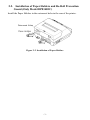
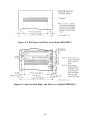
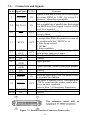
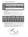
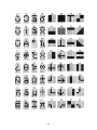
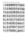
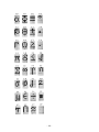
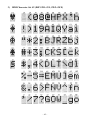
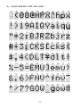
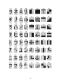
DOT MATRIX PRINTER
DP8340 SERIES
[PARALLEL INTERFACE]
USERS MANUAL
Federal Communications Commission
Radio Frequency Interference
Statement
This equipment has been tested and found to comply with the limits for a Class A digital device,
pursuant to Part 15 of the FCC Rules. These limits are designed to provide reasonable protection
against harmful interference when the equipment is operated in a commercial environment.
This equipment generates, uses and can radiate radio frequency energy and, if not installed and
used in accordance with the instruction manual, may cause harmful interference to radio
communications. Operation of this equipment in a residential area is likely to cause harmful
interference in which case the user will be required to corect the interference at his own expense.
For compliance with the Federal Noise Interference Standard, this equipment requires a
shielded cable.
This statement will be applied only for the printers marketed in U.S.A.
Statement of
The Canadian Department of Communications
Radio Interference Regulations
This digital apparatus does not exceed the Class A limits for radio noise emissions from digital
apparatus set out in the Radio Interference Regulations of the Canadian Department of
Communications.
Le présent appareil numérique n’émet pas de bruits radioélectiques dépassant les limites
applicables aux appareils numériques de la classe A prescrites dans le Règlement sur le
brouillage radioélectrique édicté par le ministère des Communications du Canada.
The above statement applies only to printers marketed in Canada.
CE
Manufacturer’s Declaration of Conformity
EC Council Directive 89/336/EEC of 3 May 1989
This product, has been designed and manufactured in accordance with the International Standards EN 50081-1/01.92 and
EN 50082-1/01.92, following the provisions of the Electro Magnetic Compatibility Directive of the European Communities as of May 1989.
EC Council Directive 73/23/EEC and 93/68/EEC of 22 July 1993
This product, has been designed and manufactured in accordance with the International Standards EN 60950, following
the provisions of the Low Voltage Directive of the European Communities as of July 1993.
The above statement applies only to printers marketed in EU.
Trademark acknowledgments
DP8340: Star Micronics Co. Ltd.
Notice
•
•
•
•
All rights reserved. Reproduction of any part of this manual in any form whatsoever, without STAR’s express
permission, is strictly forbidden.
The contents of this manual are subject to change without notice.
All efforts have been made to ensure the accuracy of the contents of this manual at the time of printing. However,
should any errors be found, STAR would greatly appreciate being informed of them.
The above notwithstanding, STAR can assume no responsibility for any errors in this manual.
© Copyright 1986, 1999 Star Micronics Co., Ltd.
TABLE OF CONTENTS
1. OUTLINE .............................................................................................. 1
2. UNPACKING AND INSTALLATION ................................................ 2
2-1. Unpacking .................................................................................... 2
2-2. Installation of Paper Holders and Re-Roll Prevention Guard
(Only Model DP-8340FC) ........................................................... 3
2-3. Handling Notes............................................................................. 4
3. PART IDENTIFICATION AND NOMENCLATURE ........................ 5
3-1. Power Supply Unit ....................................................................... 5
3-2. Printer ........................................................................................... 6
3-3. Part Functional Description.......................................................... 7
4. INSTALLATION OF INK RIBBON AND PAPER ............................. 8
4-1. Installation of Ink Ribbon ............................................................ 8
4-2. Removal of Ink Ribbon ................................................................ 9
4-3. Paper Insertion ........................................................................... 10
4-3-1. Model DP8340FC ........................................................... 10
4-3-2. Model DP8340SC ........................................................... 11
4-4. Paper Removal ........................................................................... 12
5. CONTROL CODES ............................................................................ 13
6. GENERAL SPECIFICATIONS .......................................................... 22
7. INTERFACE ....................................................................................... 26
7-1. Interface Specifications .............................................................. 26
7-2. Interface Timing ......................................................................... 26
7-3. Connectors and Signals .............................................................. 27
7-4. Setting of DIP Switches ............................................................. 28
7-5. Peripheral Unit Drive Circuit ..................................................... 29
7-6. Emergency Suspension .............................................................. 29
8. CHARACTER CODE LIST ................................................................ 30
9. FONT LIST ......................................................................................... 39
10. WHEN POWER IS SUPPLIED BY THE USER ............................. 52
1. OUTLINE
The DP8340 series of serial dot matrix printers is for use in ECR, POS, electronic
instruments, banking machines and computer peripheral equipment.
The DP8340 series include the following features;
1) 2 color printing (Red and Black)
2) High-speed bidirectional printing (2 line/sec, 40 columns per line)
3) 9-pin print head
4) Parallel interface (Centronics compatible)
5) Commands for expanded characters, inverted characters, emphasized characters, and red and black printing are provided, which makes the printer
very versatile.
6) Simultaneous Data Communication and Printing
7) 2 Peripheral Drivers
Model Name Notation
–1–
2.UNPACKING AND INSTALLATION
2-1.
Unpacking
After opening the box, check if all necessary accessories are included.
(A) Printer
1 Printer
2 User’s Manual
3 Paper Holders
4 Re-Roll Prevention Guard
5 Ink Ribbon
6 DIP Switch Cover
(B) Power Supply Unit
1
1 Power Supply Unit
2 User’s Manual
Figure 2-1. Unpacking
–2–
2-2. Installation of Paper Holders and Re-Roll Prevention
Guard (Only Model DP8340FC)
Install the Paper Holders in the outermost holes in the rear of the printer.
Figure 2-2. Installation of Paper Holders
–3–
Install the Re-Roll Prevention Wire in the holes of the printer cover. Twisting the
Wire as shown in the figure below, will make the installation easier.
Figure 2-3. Installation of Re-Roll Prevention
2-3.
Handling Notes
(1)
(2)
(3)
Install the printer near an easily accessible socket-outlet.
Place the unit on a flat and stable surface for operation.
Do not connect the AC Power Plug to the same outlet used for other noise
generating devices (large motors, etc.).
(4) Be careful not to drop paper clips, pins and other foreign objects into the
unit.
(5) Wipe off dirt with a soft cloth soaked in alcohol or benzine. Do not use
Lacquer thinner, Trichlorethelene or Ketone solvents because they may
damage plastic parts.
(6) Use a soft brush, etc. for cleaning the printer mechanism and PCB.
(7) Keep hands out of printer while power is on.
(8) Do not attempt to print when there is no ink ribbon or paper in the unit. The
print head life could be severly reduced.
(9) If the paper is fastened tightly to the roll, the paper may not detach from the
roll when the end is reached.
If this happens, the no paper detection function and paper feed will not
operate.
(10) Always keep the printer cover attached when printing to prevent paper
jams, noise, and other problems.
(11) Always turn the power off before opening the printer cover. (e.g. When
renewing a ink ribbon)
–4–
3.PART IDENTIFICATION AND NOMENCLATURE
3-1.
Power Supply Unit
DC Power Connector (Output)
Shape of AC Power plug will
vary according to destinations.
Figure 3-1. Power Supply Unit
–5–
3-2.
Printer
Figure 3-2. Printer: Front View
Figure 3-3. Printer: Rear View
–6–
3-3.
Part Functional Description
(1)
(2)
(3)
(4)
(5)
AC Power Plug
DC Power Outlet
Printer Cover
POWER Lamp
ON LINE Lamp
Connect to an outlet of the specified voltage.
Supplies DC 12V power to the printer.
Protects the printer against dust and reduces noise.
Lights up (green LED) when power is on.
Lights up (green LED) when the unit is in the online
mode.
(6) ALARM Lamp
Lights up (red LED) when printer operation is not
normal, or the printer is out of paper. It is necessary
to install paper into the printer and press the ON
LINE Button to recover from paper empty status.
Turn off the printer power in order to recover from
abnormal operation.
(7) ON LINE Button
Toggles between the on-line and off-line modes. The
printer will go on-line after turning power on.
(8) FEED Button
Momentary operation of this button provides one
line feed. Pressing this button continuously will
cause continuous paper feed. If power is turned on
while pressing this button, self printing*1 will be
performed.
(9) Interface Connector Connects the printer to host computers. Check that
both computer and printer are off before connecting.
(10) DIP Switches
Allows for setting of various functions according to
user requirements.
(11) Peripheral Drive
Connects the printer to the peripheral devices such
Output
as Cash Drawer, Paper Cutter and Paper Take-Up
Device etc. to drive them.
*1
Self Printing
This printer has another convenient function, the
Automatic Test Printing. With the ink ribbon and
paper properly installed in the printer, turn the power
ON while holding down the Feed switch. Test printing will start and stop again automatically.
–7–
4. INSTALLATION OF INK RIBBON AND PAPER
4-1.
Installation of Ink Ribbon
(1) Turn power off, lift the Printer Cover up and remove it.
Note: Be careful not to touch the print head immediately after printing,
because it can get very hot.
Figure 4-1. Printer Cover Removal
(2)
(3)
(4)
Unwind ribbon so that the spools are separated as shown in Figure 4-3.
Hold the ribbon taut as shown with the drive pins facing down and slide the
ribbon between the print head and the platen. While keeping the ribbon taut,
wrap one side around the black ribbon guide on the end of the platen and
drop one spool on the spool shaft. As you move the spool downwards, move
the detecting lever aside to allow the spool to drop into place. Make sure the
spool drive pins engage with the spool drive holes. As the spool drops into
place there will be a click.
While continuing to hold the ribbon taut, install the remaining ribbon spool
in a similar fashion.
Turn the spool that rotates freely to take up the ribbon slack.
Ribbon Life
Description
SF-03BR
(Fuji Kagakushi
Kogyo Co., Ltd.)
Ribbon life
Black
Red
Approx.
0.8 million
characters
–8–
Approx.
0.4 million
characters
Ribbon Life
Ribbon life
Description
Black
SF-03B
(Fuji Kagakushi
Kogyo Co., Ltd.)
Approx.
0.8 million
characters
Figure 4-2. Installation of Ink Ribbon
Figure 4-3. Ribbon Spools
4-2.
Removal of Ink Ribbon
Hold the spool and lift gently, rotating it until the ribbon sags. Push the ribbon
detecting lever out, lift the spool until it comes off the shaft. Remove the second
spool in a similar manner.
(Do not apply excessive force when lifting spools.)
–9–
4-3.
Paper Insertion
4-3-1. Model DP8340FC
(1)
(2)
(3)
(4)
Cut the Roll Paper end straight and square. Hold the roll so that the paper
comes from the bottom.
Attach the Roll Paper to the Holders Paper by slipping one side of the roll
onto the Hub and pulling the other Hub out to allow the roll to slip in place.
Insert the paper evenly into the Paper Insertion Slot.
Turn the Power Switch “ON”, and press the FEED Button. The paper will
be fed into the unit.
Figure 4-4. Paper Insertion (1) [Model DP8340FC]
Figure 4-5. Paper Insertion (2) [Model DP8340FC]
– 10 –
4-3-2. Model DP8340SC
1.
2.
3.
4.
Make a straight cut along the top of the paper, about 1/4 inch away from the
sprocket holes, (as shown in the figure). If there is perforation, cut the paper
on the perforation.
Insert the paper squarely into the paper insertion slot until the ALARM lamp
goes out. Then, hold down the FEED switch to advance the paper 8 lines,
and release the switch when 8-line feeding is completed.
If the paper is not fed straight during 8-line feeding, straighten the paper by
pulling it back slowly as you hold the paper release lever down. If a sprocket
hole is torn or enlarged, recut the paper and reinsert it as before.
After confirming that the paper has been fed in straight, feed the paper
continuously by holding the feed switch down.
Release the feed switch when the paper emerges through the paper outlet.
Figure 4-6. Paper Insertion (1) [Model DP8340SC]
Figure 4-7. Paper Insertion (2) [Model DP8340SC]
– 11 –
4-4.
Paper Removal
Cut the paper close to the slot and use the feed button until paper has passed
completely through the printer.
Note: Do not try to remove the paper by hand as it could become crooked and
get jammed inside the printer.
– 12 –
5.CONTROL CODES
CODE
FUNCTION
LF
(0A)H
Print and line feed instruction
OUTLINE
The LF code causes the data in the line buffer to be printed,
followed by a single line feed. When the line buffer is empty,
only the feed takes place.
CODE
CR
(0D)H
Print and line feed instruction
FUNCTION
OUTLINE
Same function as of LF code.
However, when the DIP switch 3 is ON, the CR code becomes
invalid.
CODE
SO
(0E)H
Expanded character instruction
FUNCTION
OUTLINE
This code causes the printer to print expanded characters
twice as wide as the regular ones. This remains in effect until
a DC4 code is received.
CODE
DC4
(14)H
Release from expanded characters
FUNCTION
OUTLINE
The expanded character instruction is released by the DC4
code, and the succeeding data is printed as regular width
characters.
CODE
ESC-1
(1B)H (2D)H (01)H or (1B)H (2D)H (31)H
Underline mode selection
FUNCTION
OUTLINE
All data received after this code is underlined until a ESC-0
is received.
CODE
FUNCTION
ESC-0
(1B)H (2D)H (00)H or (1B)H (2D)H (30)H
Release from underline mode
OUTLINE
The underline mode selection is released by this code.
– 13 –
CODE
FUNCTION
SI
(0F)H
Inverted print instruction
OUTLINE
This function causes the printing to be inverted. This code
must be received at the beginning of a line. If this code is
received anywhere other than at the beginning of a line, it is
disregarded. Accordingly, normal characters and inverted
characters, can not be mixed on the same line.
CODE
DC2
(12)H
Release from inverted print instruction
FUNCTION
OUTLINE
The inverted print instruction is released by this code. This
code must be received at the beginning of a line.
CODE
ESC E
(1B)H (45)H
Emphasized print mode instruction
FUNCTION
OUTLINE
Data following this command is printed with emphasized
characters.
In this mode, characters are printed in a single direction.
CODE
FUNCTION
ESC F
(1B)H (46)H
Release from emphasized print instruction
OUTLINE
Emphasized print is released.
CODE
ESC 4
(1B)H (34)H
Red character print instruction
FUNCTION
OUTLINE
This command causes subsequent data to be printed with red
characters.
The instruction is released by the code, ESC 5.
Red and black characters may be intermixed.
This command is ignored when DIP switch 5 is OFF.
CODE
FUNCTION
ESC 5
(1B)H (35)H
Release from red character print instruction
OUTLINE
The red character print instruction is released by this code.
– 14 –
CODE
FUNCTION
ESC R n
(1B)H (52)H n
Select an international character.
OUTLINE
This command selects one of the international character sets
in accordance with the value of “n” as shown below.
n = 0 : U.S.A.
3 : England
6 : Italy
1 : France
4 : Denmark 7 : Spain
2 : Germany 5 : Sweden
8 : Japan
International character set can be specified using the DIP
Switches. However, control code settings have priority.For
international characters, please refer to the character code
chart in Section 8, or to the font chart in Section 9.
CODE
ESC & 0 n1 n2 [m0 m1 m2 m3 m4 m5] n2-n1+1
(1B)H (26)H (00)H n1 n2 [m0 m1 m2 m3 m4 m5] n2-n1+1
Define download character.
FUNCTION
OUTLINE
In this section we will define “download characters”.
This printer is able to print the characters expressed by the
character codes in Section 8. In addition, the user can create
special characters, which are called download characters.
A maximum of ten download characters can be defined, and
the defined character pattern is stored in the printer’s RAM.
This means that if the power to the printer is turned off, stored
download characters are lost.
The range of positions in which download characters can be
written is expressed by n1, n2. It is specified by the range
(21)H
n1
n2
(7F)H. When the download character
consists of one character, the expression becomes n1 = n2.
m0 expresses the relation between the character pattern and
the print head. (See following explanation.) m1 ... m5 expresses the character pattern.
– 15 –
Relation Between Character Pattern Data and the Print Head
CODE
FUNCTION
ESC % 1
(1B)H (25)H (01)H or (1B)H (25)H (31)H
Select download character
OUTLINE
This code specifies the download mode. Download characters defined by the previously explained <ESC>&0 code
cannot be printed unless this code is first sent to the printer.
CODE
ESC % 0
(1B)H (25)H (00)H or (1B)H (25)H (30)H
Cancel download character
FUNCTION
OUTLINE
SAMPLE
This code cancels the download mode and selects standard
text characters (characters appearing in the character code
chart in Section 8).
When power is turned on, standard text characters are selected.
Let’s try an actual example of printing a download character.
We will design the download character shown below:
Next, we will define the download character.
– 16 –
If the position into which the download character is written
(the character code) is defined as (21)H, (22)H, (23)H, then
we have n1 = (21)H, n2 = (23)H The relation between the
character pattern data and the print head assigns the 9 pin as
unused. Therefore, m0 = (80)H.
If data m1 to m18 is converted to hexadecimal, it appears as
follows.
Data
m1
m2
m3
m4
m5
Binary
10100000
10100000
10111110
10100000
10100000
DATA TRANS MISSION
Hex.
A0
A0
BE
A0
A0
Data
m1
m2
m3
m4
m5
Binary Hex.
10011000 98
11100100 E4
10000010 82
11100100 E4
10011000 98
Data
m1
m2
m3
m4
m5
Binary Hex.
11111111 FF
10000011 83
10111101 BD
11000001 C1
11111111 FF
(1) Difine download (1B)H (26)H (00)H (21)H (23)H (80)H
(A0)H (A0)H (BE)H (A0)H (A0)H
(80)H (98)H (E4)H (82)H (E4)H (98)H
(80)H (FF)H (83)H (BD)H (C1)H
(FF)H
(2) Select download (1B)H (25)H (01)H
(3) Character code (21)H (22)H (23)H (A0)H
(4) Cancel download (1B)H (25)H (00)H
(5) Character code (21)H (22)H (23)H (0A)H
PRINT SAMPLE
CODE
FUNCTION
ESC a n
(1B)H (61)H n
n-line feed
OUTLINE
After printing the data in the current line, n lines are fed by this
code. The value of n ranges from 1 to 120.
CODE
ESC C n
(1B)H (43)H n
Sets page length in lines
FUNCTION
OUTLINE
This code sets the length of a page to n lines. The value of n
ranges from 1 to 120. On initialization, the page length
default condition will be 42 lines. The line feed pitch is onesixth inch.
– 17 –
CODE
FUNCTION
ESC N n
(1B)H (4E)H n
Sets bottom margin in lines
OUTLINE
Upon receiving this code, the bottom margin is set to n lines.
0
n 120; Default Value n = 0
CODE
FUNCTION
ESC O
(1B)H (4F)H
Cancels bottom margin.
OUTLINE
Upon input of this code, bottom margin setting is cleared.
CODE
FF
(0C)H
Form feed
FUNCTION
OUTLINE
The FF code prints the data in the current line and transports
the paper to the start of the next page.
CODE
ESC @
(1B)H (40)H
Printer initialization
FUNCTION
OUTLINE
All printing conditions except ESC BEL n1 n2, the line buffer
and data buffer are set to the power on default condition.
CODE
ESC BEL n1 n2
(1B)H (07)H n1 n2
Sets peripheral unit drive 1 pulse duration.
FUNCTION
OUTLINE
This command sets the pulse duration for peripheral unit
drive (Paper Cutter, Take-Up Device, cash drawer, etc.)
Pulse Duration = 10 × n1 (ms)
Delay = 10 × n2 (ms)
1
n1 127; 1
n2
127
Default value: n1 = n2 = 20
– 18 –
Executed by BEL code and FS code after printing.
CODE
FUNCTION
BEL
(07)H
Trigger peripheral unit drive (Deferred)
OUTLINE
Causes a peripheral drive pulse to be generated. This code is
normally stored in the buffer and is performed as it is received
from the data queue.
CODE
FUNCTION
FS
(1C)H
Trigger peripheral unit drive (immediate)
OUTLINE
Causes a peripheral drive pulse to be generated immediately.
CODE
SUB
(1A)H
Trigger peripheral unit drive 2 (immediate)
FUNCTION
OUTLINE
REMARKS
CODE
FUNCTION
OUTLINE
This command causes a peripheral unit drive 2 pulse to be
generated.
Pulse Duration : 200ms (fixed)
Delay
: 200ms (fixed)
It is impossible to drive peripheral devices 1 and 2 at the
same time.
CAN
(18)H
Clears print buffer
Upon input of this code the data buffer and line buffer is
cleared.
– 19 –
Character Code List
Character
Code
1 LF
2 CR
(0A)H
(0D)H
3 SO
4 DC4
5 ESC-1
(0E)H
(14)H
(1B)H (2D)H(01)H
(1B)H (2D)H (31)H
(1B)H (2D)H(00)H
(1B)H (2D)H (30)H
(0F)H
(12)H
(1B)H (45)H
6 ESC-0
7 SI
8 DC2
9 ESC E
10
11
12
13
14
15
ESC F
ESC 4
ESC 5
ESC R n
ESC & 0 ...
ESC % 1
17 ESC a n
18 ESC C n
(1B)H (46)H
(1B)H (34)H
(1B)H (35)H
(1B)H (52)H n
(1B)H (26)H (00)H ...
(1B)H (25)H (01)H
(1B)H (25)H (31)H
(1B)H (25)H (00)H
(1B)H (25)H (30)H
(1B)H (61)H n
(1B)H (43)H n
19 ESC N n
(1B)H (4E)H n
20 ESC O
21 FF
22 ESC @
(1B)H (4F)H
(0C)H
(1B)H (40)H
16 ESC % 0
Function
Print and line feed instruction
Print and line feed instruction
(same as LF)
Expanded character instruction
Expanded character release
Underline instruction
Underline release
Inverted print instruction
Inverted print release
Emphasized print instruction
(one-way printing)
Emphasized print release
Red character print instruction
Red character print release
Select an international character set
Define download character
Select download characters
Cancel download characters
n-line feed instruction5
Sets page length in lines
1
n
120 (default n = 42)
Set bottom margin in lines
0
n
120 (default n = 0)
Cancel Bottom margin
Form feed
Printer initialization instruction
– 20 –
Character
Code
23 ESC BEL
n1 n2
(1B)H (07)H
n1 n2
24 BEL
25 FS
(07)H
(1C)H
26 SUB
27 CAN
(1A)H
(18)H
Function
Set peripheral unit drive pulse duration
1
n1
127, 1
n2
127
(default n1 = n2 = 20)
Trigger peripheral unit drive 1 (Deferred)
Trigger peripheral unit drive
(Immediate)
Trigger peripheral unit drive 2 (immediate)
Clears print buffer
– 21 –
6.GENERAL SPECIFICATIONS
Printing method
Serial impact dot matrix printing,
9 wires
Number of print columns 40 columns, 12 CPI
Print speed
Approx. 2 lines/sec
Print direction
Bi-directional
Line spacing
1/6 inch
Paper feed method
Friction Feed or Sprocket-feed
Paper feed speed
Approx. 12 lines/sec
Character set
ASCII
96
Special
64
Block graphics*
64
Katakana (Japanese)
64
IBM Special
83
IBM Block graphics*
50
Download
10
Font configuration
Ordinary characters
5 × 9 dots
Block graphics*
6 × 6 dots
(6 × 8 dots)
* Graphic Feed Not Available
Character size
2.42 (H) × 1.71(W) mm
Dot spacing
0.35 (H) × 0.35 (W) mm
Print area
84.3 mm
Print Buffer
Approx. 1.5 KB
Interface
Parallel Interface (Centronics compatible)
Peripheral drive
2 outputs (each 1A max. at 12V. Both cannot
operate at the same time.)
External dimensions
(Printer)
202(W) × 200(D) × 98(H) mm
(without paper holder, DC Power Connector)
(Power supply unit)
60(W) × 120(D) × 36(H) mm (without AC cable)
Weight
(Printer)
Approx. 1.9 kg
(Power supply unit)
Approx. 0.4 kg (without AC cable)
Power supply unit
Four supplies available with following ratings
Input
Output
AC 100 – 240 V
47Hz – 63 Hz
0.8 A Max
DC 12.0 V ± 5%
2.0 A
– 22 –
Paper specification
Paper type
Size Paper width
Roll diameter
Thickness (single)
(2 copy)
Paper end
Ink ribbon specification
Color
Ribbon material
Ribbon size
Spool
Recommended ribbon
Operating conditions
Storage conditions
Head life
Printer reliability
Ordinary and carbonless copy paper
114.3 mm (4.5 inches)
80 mm outer diameter (Max)
0.07 mm (52.3 g/m2) to 0.09 mm (64g/m2)
One copy and one original (max 0.13 mm)
Paper should not be attached to the core
Black and red / Black only
Nylon (#40 denier)
13mm × 6mm
13mm (width), 35mm in diameter (two spool)
SF-03BR (Black and red), SF-03B (Black)
(manufactured by Fuji Kagakushi Kogyo Co., Ltd.)
or approved equivalent.
Temperature
+5˚C - +40˚C
Humidity
10% - 80%RH
-20˚C - +70˚C
Temperature
Humidity
5% - 95%RH (+40˚C)
70 million characters
5.0 million lines MCBF (except head life)
– 23 –
Figure 6-1. Roll Paper and Print Area [Model DP8340FC]
Figure 6-2. Sprocket-feed Paper and Print Area [Model DP8340SC]
– 24 –
60mm
Figure 6-3. External Dimensions (Printer)
36mm
120mm
2.0m
Shape of AC Power plug will
vary according to destinations.
Figure 6-4. External Dimensions (Power Supply Unit)
– 25 –
7. INTERFACE
7-1.
Interface Specifications
This printer has a parallel interface to communicate with the computer.
The operating specifications of the parallel interface are as follows.
(1) Data transfer rate
1000 to 6000 characters per second
(2) Synchronization
Via externally supplied STROBE pulses
(3) Handshaking
ACK and BUZY signals
(4) Logic level
Compatible with TTL level
7-2.
Interface Timing
Figure 7-1. Interface Timing Diagram
Signal Name
Circuit Example
DATA1-DATA8
(To Printer)
STROBE
(To Printer)
BUZY, ACK
(From Printer)
Figure 7-2. Typical Interface Circuit
– 26 –
7-3.
Connectors and Signals
Pin No.Signal Name IN/OUT
1
STROBE
IN
2-9
DATA1-8
IN
10
ACK
OUT
11
BUSY
OUT
PAPER
OUT
13 SELECTED
14-15
N/C
SIGNAL
16
GND
CHASSIS
17
GND
18
N/C
19-30
GND
12
OUT
OUT
Signals when data is ready to be read.Signal
gose from HIGH to LOW (for at least 0.5
microsec.) when data is available.
These signals provide the information of the
first to eighth bits of parallel data.Each signal
is at HIGH level for a logical 1 and at a LOW
level for a logical 0.
A 9 microsecond LOW pulse acknowledges
receipt of data.
When this signal goes LOW, the printer is ready
to accept data. When the printer is in one of
the conditions below.”HIGH” is set.
1. Data being entered.
2. Off line.
3. Error condition.
This signal is normally LOW. It will go HIGH
if the printer runs out of paper.
This signal is HIGH when the printer is online.
Unused
Signal ground.
Chassis ground, isolated from logic ground.
31
RESET
IN
32
ERROR
OUT
33 EXT GND
34-36
N/C
Function
Unused
Twisted pair return signal ground level.
When this signal gose LOW, the printer is reset
to its power-on condition.
This signal is normally HIGH. This signal goes
LOW to signal that the printer cannot print
due to an error condition.
Refer to Item 7-6 Emergency Suspension.
External ground.
Unused.
Figure 7-3. Parallel Interface Connector (Printer side)
– 27 –
7-4.
Switch
1
2
3
4 (*1)
5 (*2)
6
7
8
Setting of the DIP Switches
Factory settings : all ON
ON
OFF
Function
Character Table (See below)
Control cord CR
Printing Direction (Red printing)
Ink Ribbon
Disable
Bi.
2-color
Enable
Uni.
monochrome
International Character Set (See below)
(*1) DIP Swich 4 should be set to OFF when you use 2-part sprocket
paper having the seam on the right since the ribbon snags at the
seam if shifted.
The DIP Switch 4 Should be otherwise set to ON.
(*2) DIP Swich 5 should be set to ON when you use a 2-color ribbon
for 2-color printing.
It should be set to OFF when a monochrome ribbon is used.
Character Table
SW NO.
1
2
USA & Europe
ON
ON
IBM#1
OFF
ON
IBM#2
ON
OFF
JAPAN
OFF
OFF
International Character Set
SW NO.
6
7
8
USA
ON
ON
ON
France Germany England Denmark Sweden
OFF
ON
OFF
ON
OFF
ON
OFF
OFF
ON
ON
ON
ON
ON
OFF
OFF
Itary
ON
OFF
OFF
Spain
OFF
OFF
OFF
Note: When DIP Switches 1 and 2 are set to OFF, the printer always
selects the Japan international character set regardless of the status
of DIP Switches 6, 7 and 8.
When DIP Swiches 1 and 2 are otherwise set, the printer selects
the character set determined by DIP Switches 6, 7 and 8.
Each international character set is selectable through software
regardless of the selection by DIP Switches.
Figure 7-4. DIP Switch Setting
– 28 –
7-5.
Peripheral Unit Drive Circuit
The Control Board of this printer is equipped with a circuit for driving peripheral
units (Paper Cutter, Take-Up Device, Cash Drawer, etc.)
The 6P Modular Jack is used as the Drive Circuit. When using this circuit,
connect the peripheral unit cable to the 6P Modular Jack (cable is not included).
Note: Peripheral unit drive circuit connector only connects to peripheral units
such as cash drawers, etc.
Do not connect it to a telephone.
1. Drive Circuit
Drive
Output
D1
D2
12V,MAX. 1A
Absolute Ratings (Ta = 25˚C)
Voltage Breakdown
100V
Peak Forward Current
1A
Note: It is impossible to drive peripheral devices 1 and 2 at
the same time
[Printer side]
Figure 7-5. Drive Circuit
Figure 7-6. 6P Modular Jack
Connector
Figure 7-7. Recommend Cable
Note: Make sure that the metal structural parts of the peripheral device are
connected to frame Ground (Pin 1) to provide a static drain path.
2. Control code
Codes for Drive Circuit control are ESC BEL n1 n2, BEL, FS and SUB.
Refer to the Control Codes in Section 5.
7-6.
Emergency Suspension
If an error condition is detected during operation, the printer will stop printing and
ERROR signal will go Low.
It is necessary to turn the printer power off and on again in order to recover from
the emergency suspension.
This printer can detect the following error conditions:
a. Motor Lock
b. Defective timing detector
– 29 –
8. CHARACTER CODE LIST
1) U.S.A. & Europe (DIP SW1: ON, SW2:ON)
– 30 –
– 31 –
2) IBM Character Set #1 (DIP SW1: OFF, SW2: ON)
– 32 –
– 33 –
3) IBM Character Set #2 (DIP SW1: ON, SW2: OFF)
– 34 –
– 35 –
4) JAPAN (DIP SW1: OFF, SW2: OFF)
– 36 –
– 37 –
International Character Sets
– 38 –
9. FONT LIST
1) U.S.A. & Europe (DIP SW1: ON, SW2:ON)
– 39 –
– 40 –
– 41 –
2) IBM Character Set #1 (DIP SW1: OFF, SW2: ON)
– 42 –
– 43 –
– 44 –
3) IBM Character Set #2 (DIP SW1: ON, SW2: OFF)
– 45 –
– 46 –
– 47 –
4) JAPAN (DIP SW1: OFF, SW2: OFF)
– 48 –
– 49 –
– 50 –
International Character Sets
– 51 –
10. WHEN POWER IS SUPPLIED BY THE USER
When printer power is supplied by the user rather than through the accessory
power source unit, please be careful of the following points.
Note 1: The power supply must be +12V +10%
–5% 2A or above. An electrolytic capacitor (C = 4700µF/25V to 6800µF/25V) must be connected across
the output of the power supply.
Note 2: A DC power plug is available as an option.
GND
+12V
GND
Reference: Design the power supply referring to the power supply circuit shown
below.
Note: A line noise filter must be used to prevent line transients from passing
through power supply. Filter design to be determined by environmental
noise requirements.
– 52 –
VAC
14V
C2
100 ~ 200µF/25V
VDC
12V +10%
–5%
ZD1
VZD = 14V (1W)
IAC
C1
2 ~ 3A
6800µF/25V
C3
TR1
4700 ~ 6800µF/25V
2SD633 (TOSHIBA)
Other parameters may be determined by user.
Figure 10-1. Power Supply Reference Circuit
– 53 –
- MEMO -
ELECTRONIC PRODUCTS DIVISION
STAR MICRONICS CO., LTD.
OVERSEAS SUBSIDIARY COMPANIES
STAR MICRONICS AMERICA, INC.
536 Nanatsushinnya, Shimizu, Shizuoka
424-0066 Japan
Tel: 0543-47-0112, Fax: 0543-48-5013
1150 King Georges Post Road, Edison, NJ 08837-3729 U.S.A.
Tel: 732-623-5555, Fax: 732-623-5590
http://www.starmicronics.com
STAR MICRONICS U.K. LTD.
Please access the following URL
http://www.star-micronics.co.jp/service/
frame_sp_spr_e.htm
for the lastest revision of the manual.
Star House, Peregrine Business Park, Gomm Road,
High Wycombe, Bucks, HP13 7DL, U.K.
Tel: 01494-471111, Fax: 01494-473333
http://www.starmicronics.co.uk
1999.05.30
Printed in Japan, 80870175


![User's Manual DP8340II SERIES [Parallel]](http://vs1.manualzilla.com/store/data/006876520_1-e14f27ca3e82bd4fbe61e6010073af1e-150x150.png)


![User`s Manual DP8340II R SERIES [Serial]](http://vs1.manualzilla.com/store/data/005993516_1-f706d7540b19c5fecea062c6335f03cc-150x150.png)

![User's Manual DP8340II SERIES [Serial]](http://vs1.manualzilla.com/store/data/006863352_1-7c329c58d43827994f443f796586090a-150x150.png)