1
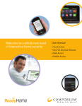
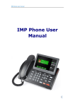
SMCRB5701-Z TouchScreen
FastFind Links
Introduction
Configuring the TouchScreen
User Manual
Managing System Security
Managing Connectivity Between the TouchScreen
and Monitoring Stations
Managing Connectivity Between Home Devices
and the Internet
Managing Environmental Devices
Maintaining and Configuring the TouchScreen
SMC Networks
20 Mason
Irvine, CA. 92618
U.S.A.
Copyright © 2011 SMC Networks
All Rights Reserved
Information furnished by SMC Networks, Inc. (SMC) is believed to be accurate and reliable. However,
no responsibility is assumed by SMC for its use, or for any infringements of patents or other rights of
third parties which may result from its use. No license is granted by implication or otherwise under
any patent or patent rights of SMC. SMC reserves the right to change specifications at any time
without notice
No part of this publication may be reproduced or transmitted in any form or by any means, electronic
or mechanical, including photocopying and recording, or stored in a database or retrieval system for
any purpose without the express written permission of SMC.
Microsoft and Windows are registered trademarks of Microsoft Corporation. Apple and Macintosh are
registered trademarks of Apple, Inc. All other brands, product names, trademarks, or service marks
are property of their respective owners.
This product (Model: SMCSMCRB5701-Z) includes software code developed by third parties,
including software code subject to the GNU General Public License (―GPL‖) or GNU Lesser General
Public License (LGPL‖). As applicable, the terms of the GPL and LGPL, and information on obtaining
access to the GPL code and LGPL used in this product, are available to you at http://gpl.smc.com/.
The GPL code and LGPL code used in this product is distributed WITHOUT ANY WARRANTY and is
subject to the copyrights of one or more authors. For details, see the GPL Code and LGPL Code for
this product and the terms of the GPL and LGPL.
SMCRB5701-Z TouchScreen User Manual
July 18, 2011
Contents
Preface.................................................................................................................... vii
Document Organization .......................................................................................... viii
Changes to this Revision ........................................................................................ viii
Document Conventions ............................................................................................ ix
Safety and Warnings ................................................................................................ ix
Typographic Conventions .......................................................................................... x
1 Introduction ......................................................................................................... 11
Understanding Security Components....................................................................... 12
Understanding Security Zones ................................................................................. 12
Understanding Alarms ............................................................................................. 13
2 Configuring the TouchScreen ........................................................................... 14
Overview ................................................................................................................. 15
Subscriber Portal ..................................................................................................... 16
Understanding the TouchScreen Controls ............................................................... 16
Understanding the Screen ................................................................................. 17
Security Status Header ...................................................................................... 17
System & Zone Trouble Header ......................................................................... 18
Content Area...................................................................................................... 22
Home Screen ............................................................................................... 23
TouchScreen Apps (Widgets)....................................................................... 25
Installing TouchScreen Apps ............................................................................. 26
Reordering Apps on the Home Screen ......................................................... 27
Uninstalling Apps ......................................................................................... 28
Low Power Mode ..................................................................................................... 30
Show Security Cameras and Live Video .................................................................. 31
3 Managing System Security ................................................................................ 33
Understanding Arming Modes ................................................................................. 34
Arm Away Mode ........................................................................................... 35
Arm Stay Mode ............................................................................................ 36
Arm Night Mode ........................................................................................... 37
Arming and Disarming the System ........................................................................... 37
Disarming the System .................................................................................. 38
Arming the System ....................................................................................... 41
Canceling the Arming Process ..................................................................... 43
iii
SMCRB5701-Z TouchScreen Security System User Manual
Contents
Quickarming the System .............................................................................. 44
Sending an Emergency Alarm ...................................................................... 45
Protecting Against Smash-and-Grab Attacks ............................................... 46
Managing Sensors ................................................................................................... 46
Disabling a Sensor ............................................................................................. 46
Viewing Your Zone Event History ....................................................................... 48
Managing Cameras ................................................................................................. 49
Editing Key Fobs ..................................................................................................... 55
Testing Your Alarms ................................................................................................ 55
4 Managing Connectivity Between the TouchScreen and Monitoring
Stations ............................................................................................................. 59
Viewing Signal Strength ............................................................................... 60
Testing Your Connectivity ............................................................................ 60
5 Managing Connectivity Between Home Devices and the Internet.................. 61
Overview ................................................................................................................. 62
Granting Home Network Router Access to the Internet ............................................ 63
Hiding Access to Your Home Network Router from the Internet ............................... 65
Managing the Passcodes in your Security System................................................... 66
Managing Keypad Codes ................................................................................... 66
Understanding the Duress Keypad Code ........................................................... 67
Managing Your Secret Word .............................................................................. 68
Viewing Your Security Account Information ............................................................. 68
6 Managing Environmental Devices..................................................................... 69
Managing Lights ...................................................................................................... 70
Dimming or Turning Off Lights ........................................................................... 70
Modifying the Details of Your Lights ................................................................... 71
Adding a Lighting Device ................................................................................... 72
Removing a Lighting Device from the TouchScreen ........................................... 73
Managing Thermostats ............................................................................................ 73
7 Maintaining and Configuring the TouchScreen ............................................... 76
Rebooting the TouchScreen .................................................................................... 77
Recalibrating the TouchScreen ................................................................................ 77
Configuring TouchScreen Brightness and Dimming ................................................. 78
Manually Placing the TouchScreen in Night Mode ............................................. 79
Configuring Default Screen Brightness .............................................................. 79
Configuring Automatic Screen Dimming and Night Mode Dimming .................... 80
Configuring the Screen to Dim After a Period of Time Elapses (Night Mode) ..... 81
Configuring the Screensaver ................................................................................... 82
iv
SMCRB5701-Z TouchScreen Security System User Manual
Contents
Configuring Tones and Volume Levels .................................................................... 83
Setting Event Tones........................................................................................... 83
Setting Tone Volume Used When a Zone Event Occurs .................................... 85
Cleaning the TouchScreen ...................................................................................... 86
Viewing TouchScreen Specifications ....................................................................... 86
Appendix A - Using the Key Pad .......................................................................... 87
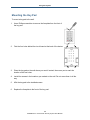
Mounting the Key Pad ............................................................................................. 88
Changing Key Pad Batteries .................................................................................... 89
Checking System Status .......................................................................................... 89
Arming the System .................................................................................................. 89
Arm Away Mode................................................................................................. 89
Arm Stay ............................................................................................................ 90
Disarming the System .............................................................................................. 90
Sending an Emergency Police Alarm ....................................................................... 90
Appendix B - Using the Key Fob .......................................................................... 91
Changing the Batteries in the Key Fob..................................................................... 92
Checking System Status .......................................................................................... 92
Arming the System .................................................................................................. 93
Arm Away Mode................................................................................................. 93
Arm Stay ............................................................................................................ 93
Disarming the System .............................................................................................. 93
Sending an Emergency Police Alarm ....................................................................... 93
Appendix C - TouchScreen Installation & Maintenance ..................................... 94
Battery Requirements .............................................................................................. 94
Installation Information ............................................................................................. 94
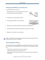
TouchScreen Installation Options ...................................................................... 94
Positioning the TouchScreen ............................................................................. 94
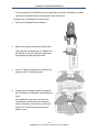
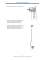
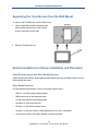
Mounting the TouchScreen on the Wall Mount ........................................................ 96
Separating the TouchScreen from the Wall Mount ................................................... 99
Recommendations for Sensor Installation and Placement ....................................... 99
Door/Window Sensors and Glass Break Detectors ............................................ 99
Glass Break Detectors ....................................................................................... 99
Motion Detectors .............................................................................................. 100
Smoke Detector Installation Recommendations ..................................................... 101
Camera Installation Recommendations ................................................................. 102
System Limitations................................................................................................. 102
Emergency Preparation ......................................................................................... 102
v
SMCRB5701-Z TouchScreen Security System User Manual
Contents
Appendix D - Quick-Reference Tables ............................................................... 104
Appendix E - Compliances ................................................................................. 107
E.1 FCC Notice...................................................................................................... 107
E.2 Device Purpose ............................................................................................... 107
E.3 UL1023 Notice................................................................................................. 107
E.4 UL985 Notice .................................................................................................. 107
E.5 UL1635 Notice................................................................................................. 108
E.6 ULC S545 Notice............................................................................................. 108
E.7 UL985 Notice .................................................................................................. 108
E.8 ETL Notice ...................................................................................................... 108
E.9 Limitations of Security Products ...................................................................... 108
Index ..................................................................................................................... 109
vi
SMCRB5701-Z TouchScreen Security System User Manual
Preface
Congratulations on your purchase of the SMCRB5701-Z Security, Monitoring, and
Automation Gateway security system. This manual contains all the information you need to
use the security system.
By reading this document, you will learn how to:
Operate the TouchScreen device
Arm and disarm your security system
Send a panic alarm
View system status and arm/disarm the system
Manage connectivity between the TouchScreen and the Central Monitoring Stations
Manage pass codes
Manage security zones
Manage emergency dispatch contact information
View history logs
View account information
vii
SMCRB5701-Z TouchScreen Security System User Manual
Preface
Document Organization
This document consists of the following chapters and appendixes.
Chapter 1 – provides an overview of the Security system, describes the system
requirements, and provides a quick reference for setting up the Security system in a
customer premises.
Chapter 2 – describes how to configure the Security system.
Chapter 3 – describes how to manage system security.
Chapter 4 – describes how to manage connectivity between the TouchScreen and
monitoring stations.
Chapter 5 – describes how to manage connectivity between home devices and the
Internet.
Chapter 6 – describes how to manage lights and thermostats.
Chapter 7 - describes how to maintain and configure the TouchScreen.
Appendix A - describes how to use the key pad.
Appendix B - describes how to use the key fob.
Appendix C - provides TouchScreen installation and maintenance information.
Appendix D - includes quick-reference tables.
Changes to this Revision
Added a new ―Compliances‖ section on page vii.
Under ―Understanding Security Zones,‖ added a note below Table 1-1 about bypassing
zones.
Added the note on page 15.
Replaced Figure 2-1.
In Table 2-2:
–
Revised the description for the message ―Broadband connection failed.‖
–
Added the new message ―Camera Connection Failed.‖
–
Revised the resolution for the message ―Sensor Battery Low.‖
–
Revised the cause and resolution for the message ―Sensor Communication Failure.‖
–
Revised the cause and resolution for the message ―Sensor Tamper Detected.‖
viii
SMCRB5701-Z TouchScreen Security System User Manual
Preface
Updated the sections ―Understanding the TouchScreen Controls,‖ ―Low Power Mode,‖
and ―Show Security Cameras and Live Video.‖
Under ―Arming and Disarming the System,‖ added new second bullet about the Security
app screen appearing.
Revised the procedures ―Disabling a Sensor‖ and ―Viewing Your Zone Event History.‖
Revised the procedure ―Viewing Signal Strength‖ and ―Testing Your Connectivity.‖
Added new Chapter 6, ―Managing Environmental Devices.‖
Added the new section ―Recalibrating the TouchScreen.‖
Revised the procedure ―Cleaning the TouchScreen.‖
Revised the procedure ―Sending an Emergency Police Alarm.‖
Added new Appendix E - Compliances, which lists the compliance information for the
RB5701-Z TouchScreen.
Document Conventions
This document uses the following conventions to draw your attention to certain information.
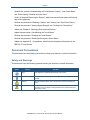
Safety and Warnings
This document uses the following symbols to draw your attention to certain information.
Symbol
Meaning
Description
Note
Notes emphasize or supplement important points of the main text.
Tip
Tips provide helpful information, guidelines, or suggestions for performing tasks more
effectively.
Warning
Warnings indicate that failure to take a specified action could result in damage to the
device.
Electric Shock Hazard
This symbol warns users of electric shock hazard. Failure to take appropriate
precautions such as not opening or touching hazardous areas of the equipment could
result in injury or death.
ix
SMCRB5701-Z TouchScreen Security System User Manual
Preface
Typographic Conventions
This document also uses the following typographic conventions.
Convention
Description
Bold
Indicates text on a window, other than the window title, including menus, menu options, buttons, fields, and labels.
Italic
Indicates a variable, which is a placeholder for actual text provided by the user or system. Angled brackets (< >)
are also used to indicate variables.
screen/code
Indicates text that is displayed on screen or entered by the user.
< > angled
brackets
Indicates a variable, which is a placeholder for actual text provided by the user or system. Italic font is also used to
indicate variables.
[ ] square
brackets
Indicates optional values.
{ } braces
Indicates required or expected values.
| vertical bar
Indicates that you have a choice between two or more options or arguments.
x
SMCRB5701-Z TouchScreen Security System User Manual
1 Introduction
Before you configure the SMCRB5701-Z security system, become familiar with the concepts
described in the following sections in this chapter:
Understanding Security Components (page 12)
Understanding Security Zones (page 12)
Understanding Alarms (page 13)
11
SMCRB5701-Z TouchScreen Security System User Manual
Introduction
Understanding Security Components
The equipment associated with the Security system includes:
TouchScreen - the device used to interface with your security system.
A/C Adapter - provides power to the TouchScreen from an outlet in your secured
premises.
Doorway/Window Sensor - monitors the opening and closing of potential entry and exit
points.
Indoor Motion Sensor - monitors movement within the premises.
Indoor camera - can be configured to take a series of pictures if a particular sensor is
faulted. Up to six cameras can be installed in your security system.
Security Network Router - the hub of your security network. This device is installed
between your broadband modem and home network router.
Thermostats - remotely controls the indoor temperature of the premises.
Smoke Detector - sounds an alarm when smoke is detected.
Lights - devices that can be remotely controlled using the security system.
Understanding Security Zones
Security zones are the sensors that detect movement and the opening and closing of doors
and windows. The sensors communicate wirelessly with your TouchScreen. Security zones
are added to the system and configured by your installer. You can enable and disable each
security zone using the Security widget. For more information about Entry/Exit delays, see
―Understanding Arming Modes‖ on page 34.
12
SMCRB5701-Z TouchScreen Security System User Manual
Introduction
Table 1-1. Types of Security Zones
Security Zone
Function
Entry/exit
Description
For doorways that are used to enter the premises.
Sensor Type
Door/Window
When the system is armed, faulting this type of sensor starts an
Entry Delay countdown rather than sending an immediate alarm.
During Exit Delay, this zone can be repeatedly faulted. Doorways
can be configured to be entry/exit or non-entry/exit.
Perimeter
If faulted when the system is armed or during an Entry/Exit delay, an
alarm is tripped.
Door/Window sensor
Motion detector
Glass Break detector
Interior Follower
Monitors the internal living spaces of the premises and triggers an
immediate alarm if the system is armed in Away mode.
Motion detector
Not armed when the system is in Armed Stay mode.
24-Hour Inform
When this security zone is tripped, there is no alarm; however, an
event is recorded in the history and the TouchScreen makes a
configured sound.
Door/Window sensor
Motion detector
Glass Break detector
24-Hour Fire
Generates an immediate fire alarm if triggered.
Smoke alarm
Note: To bypass a zone from the TouchScreen, touch Turn Zone Off and enter
your passcode. To bypass a zone from a Honeywell Vista 20P keypad, enter your
user code, press the Bypass key, and press the 2-digit number of the zone to be
bypassed.
Understanding Alarms
When an alarm is tripped, an audible alert sounds. From that point, you have a specific
amount of time (default: 30 seconds) to enter your keypad code. If a valid keypad code is not
entered within a specific time (default: 30 seconds) of the audible alarm sounding, a
message is sent to a central-monitoring station. For more information, see ―Disarming the
System‖ on page 38.
The central-monitoring station tries to contact the persons listed on the account. If the station
reaches a person listed on the account, the station asks for the Secret Word to affirm
whether a genuine emergency is occurring. If no one on the list can be contacted, or if the
person contacted gives the wrong Secret Word, the central-monitoring station dispatches
police or other appropriate emergency personnel immediately.
If the alarm is not cleared within 4 minutes, the system resets, so it can monitor additional
alarm events. If a sensor is faulted too many times, resulting in alarms, no more alarms are
sent to central monitoring for 48 hours or until the security system is disarmed.
13
SMCRB5701-Z TouchScreen Security System User Manual
2 Configuring the TouchScreen
This chapter described how to configure the TouchScreen.
The topics covered in this chapter are:
Overview (page 15)
Subscriber Portal (page 16)
Understanding the TouchScreen Controls (page 16)
Low Power Mode (page 30)
Show Security Cameras and Live Video (page 31)
14
SMCRB5701-Z TouchScreen Security System User Manual
Configuring the TouchScreen
Overview
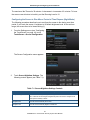
The TouchScreen’s default settings are configured from the Settings widget. To access the
Settings widget, use the following procedure.
Note: You cannot access the Security widget if the security system is armed.
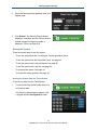
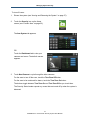
1.
From the Home screen (see Figure 2-1 on
page 16), touch the Settings app.
The Keypad screen appears.
2.
Touch the numbers to enter your keypad
code. The Settings menu appears.
From the Settings app, you can:
–
Manage Quickarm settings – see page 44.
–
Manage how sensors are listed in TouchScreen reports and tools – see page 48.
–
Manage your cameras – see page 49.
–
Test your alarms – see page 55.
–
View and test the TouchScreen’s connectivity to the central-monitoring stations – see
page 55.
–
Manage your keypad codes and secret word – see page 66
15
SMCRB5701-Z TouchScreen Security System User Manual
Configuring the TouchScreen
–
View your account information – see page 68.
–
Manage your TouchScreen sounds, screensaver, and so on – see page 76.
–
View technical information about your TouchScreen – see page 86.
Subscriber Portal
The Subscriber Portal is a Web-based tool that lets you connect to your Security system
remotely. You can access the Subscriber Portal from a PC or mobile Internet device. Many
operations that can be performed from the TouchScreen can also be performed from the
Subscriber Portal. Some operations, such as modifying your account information or
managing which widgets are accessible from your TouchScreen, can only be performed
from the Subscriber Portal.
Your installer has provided you with the URL address of the Subscriber Portal, along with a
username and password for accessing the Subscriber Portal.
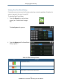
Understanding the TouchScreen Controls
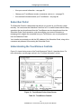
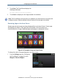
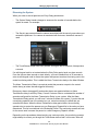
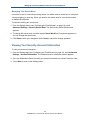
Figure 2-1 shows the key areas of the TouchScreen and Table 2-1 describes them. For
more information, see the page number in the ―For More Information‖ column.
Figure 2-1. TouchScreen Device Home Screen
Table 2-1. TouchScreen Controls
16
SMCRB5701-Z TouchScreen Security System User Manual
Configuring the TouchScreen
Control
Description
For More
Information
Screen
Interfaces with your TouchScreen
See page 17
Home button
Press this button to go to the TouchScreen Home screen. The button is
located at the bottom-center in front of the device.
See page 23
Quickarm button
Press this button to start the Quickarm function. The button is located at
the bottom left in front of device. When A/C power is available, this button
is lit.
See page 44
Panic button
Press the
button and then touch Fire to send an alarm for
emergency fire assistance, Medical to send an alarm for emergency
medical assistance, or Police to send an alarm for police assistance.
See page 45
Understanding the Screen
The TouchScreen screen is used to interface with your security system. It provides:
A real-time view of the system statuses
Tools to manage your security system
Additional optional applications
If the screen is black (showing nothing), it means the system is not receiving A/C power. The
display is powered off to conserve battery life.
The screen is organized into the following sections:
Security Status Header - see ―Security Status Header,‖ below.
System & Zone Trouble Header - see page 18.
Date/Time Bar - see Figure 2-1.
Content Area - see page 22.
Security Status Header
The Security Status header in the top-left area of the TouchScreen shows whether the
system is armed or disarmed, along with other information. Touch this header to arm or
disarm the system.
17
SMCRB5701-Z TouchScreen Security System User Manual
Configuring the TouchScreen
During troubles that would prevent arming, such as if a monitored door or window is opened,
an announcement replaces the Arm/Disarm status. For example:
If you touch this header at this time, the Arm System tab of the Security widget appears:
During the Exit Delay, the header changes to show the number of seconds before the
system is armed. For example:
During the Entry Delay, the header changes to show the number of seconds before the
system is armed. For example:
System & Zone Trouble Header
The System & Zone Trouble header appears in the top-right area of the TouchScreen when:
There is a connectivity (cellular, broadband, etc.) or a power problem with the
TouchScreen.
A sensor goes down, such as due to a battery failure.
A sensor is being tampered with, such as the cover being opened.
18
SMCRB5701-Z TouchScreen Security System User Manual
Configuring the TouchScreen
When the system reports trouble, it sounds an audible alert regularly to ensure you are
aware of the problem.
If a System & Zone header appears, touch it to display the Troubles list. The Troubles list
shows all the current troubles with TouchScreen and the sensors. For example:
Touch the text next to the
to view help about resolving the trouble. For example:
Touch
to mark the trouble as acknowledged
. An acknowledged trouble mutes its
audible alerts for 12 hours. After that time, the trouble begins alerting again. You must
acknowledge it by tapping the OK button again to silence the alerts.
From the resolution information, you can:
Touch Return to view the Troubles list again, and choose to acknowledge the current
trouble or view the resolution information for other troubles.
Touch Acknowledge Problem to acknowledge the current trouble immediately and
return to the Troubles list.
19
SMCRB5701-Z TouchScreen Security System User Manual
Configuring the TouchScreen
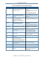
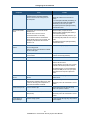
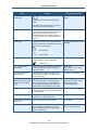
Table 2-2. System & Zone Trouble Header Messages
Component
AC Power Loss
Cause
TouchScreen is not receiving A/C power.
The system is in Low Power Mode (see “Low
Power Mode” on page 30).
Solution
Confirm that the power adapter is plugged into the
TouchScreen.
Confirm that the power adapter is plugged into an
unswitched outlet.
Confirm that the unswitched outlet has power.
Install the power adapter into another outlet.
Alarm communication
failed
The TouchScreen is neither accessing the
Internet through the local network nor has cellular
connectivity.
Restore Internet connectivity as soon as possible.
Battery failure
The TouchScreen backup battery is dead and
there is a loss of external power.
When AC power is restored, the battery will
recharge. If not, check the battery connection.
If the lack of cellular connectivity persists, contact
Customer Care.
After external power is restored, it takes
approximately 21 hours for the battery to fully
charge.
Battery Low
Battery for the identified sensor is low. See
“Sensor Battery Low” later in this table.
Confirm that the power adapter is plugged into an
unswitched outlet.
If A/C power is connected but has been off for an
extended period, the battery may still be charging.
Battery Removed
The TouchScreen battery has become detached.
Open the battery cover and check the battery
connection.
Broadband connection
failed
The TouchScreen is not accessing the Internet
through the local network, but the device still has
cellular connectivity.
Restore Internet connectivity as soon as possible.
Camera Connection
Failed
The TouchScreen cannot communicate with one
of your IP cameras.
Be sure the camera is powered on and within range
of the Wi-Fi router. The power indicator light on the
camera should be ON solid.
Cellular communication
failed
The TouchScreen cannot communicate over the
cellular network.
If this problem persists, contact Customer Care.
Communication Jammed
The TouchScreen has detected an attempt to jam
its communication with the sensors.
This could be a burglary in progress.
Cellular connectivity allows only enough
communication with central monitoring to
communicate major events such as alarms.
Someone is using a device designed to scramble
the radio-frequency (RF) signal of the sensors.
Lost Power
External power for the sensor or device named in
this alert is not connected. Applies to devices that
require external power.
Restore power to the sensor or device as soon as
possible to avoid draining the battery.
Low Battery Detected
Battery for the identified sensor is low.
Replace the battery as soon as possible.
Needs Cleaning
Sensor named in this alert is dirty or dusty
Clean the identified sensor.
Network connection failed
No broadband or cellular connectivity to the
TouchScreen.
Restore Internet connectivity as soon as possible.
Contact Customer Care to report your loss of
cellular connectivity.
20
SMCRB5701-Z TouchScreen Security System User Manual
Configuring the TouchScreen
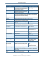
Component
Sensor Battery Low
Cause
Battery for the sensor named in this alert is low. A
low battery report is issued when the battery
reaches 2.75v for sensors and key pads, and
2.6v for key fobs.
Solution
Replace the battery as soon as possible.
Replace with a battery of the same size and
capacity.
If you cannot replace the battery immediately, you
can acknowledge the problem (touch OK in the
Troubles list) for now to arm your system.
If the problem persists after replacing the battery,
contact Customer Care.
Sensor Communication
Failure
TouchScreen cannot communicate with the
identified sensor.
The most common cause for a sensor
communication failure is a low battery.
The TouchScreen checks its communication
integrity with the sensors every 27 minutes. This
message is posted when the sensor fails two
checks in a row.
Sensor Communication
Jammed
TouchScreen communications with the identified
sensor is being jammed.
Replace the battery or replace the sensor.
Replace the battery immediately with a battery of
the same size and capacity.
If you cannot replace the battery at this time, you
can acknowledge the problem for now to arm your
system.
If the problem persists after replacing the battery,
contact Customer Care.
This could be a burglary in progress.
Someone is using a device designed to scramble
the sensor’s RF signal.
Sensor Lost Power
External power for the identified sensor or device
is not connected.
Restore power to the sensor or device as soon as
possible to avoid draining the battery.
Sensor Needs Cleaning
Identified smoke detector is dirty or dusty.
Clean the identified smoke detector.
Sensor Tamper Detected
Cover of the identified sensor has been removed.
Be sure the sensor cover on the sensor is securely
attached to the sensor base.
For smoke detectors, be sure the cover is securely
positioned in the twist-lock position on the base.
If the problem persists, you can acknowledge the
problem (touch ACK) for now to arm your system
until Customer Care can provide a permanent
solution.
Sensor Test Button
Pressed
The Test button for the identified sensor was
pressed.
If a sensor test is not in progress, check the
identified sensor.
System Battery Low
The TouchScreen has lost A/C power and is on
battery backup. The battery voltage is 3.7v, which
is about 5% remaining power. Complete loss of
power to the TouchScreen is imminent.
Check the A/C adapter.
System not ready to Arm
A door or window is open.
Open the Security app and check the security
zones for an open door or window.
System Power Lost
The TouchScreen has lost A/C power and is on
battery backup.
Check the A/C adapter.
Firmware is being updated.
No action required. Message will go away when the
update completes.
System Upgrade in
Progress Message
Restore A/C power to the TouchScreen as soon as
possible.
Restore A/C power to the TouchScreen as soon as
possible.
21
SMCRB5701-Z TouchScreen Security System User Manual
Configuring the TouchScreen
Component
System will not Arm
Cause
You entered an invalid keypad code when trying
to arm the system.
Solution
Try to enter the security code again.
Use the Settings app to add, edit, and delete
keypad codes.
Contact Customer Care.
Tamper Detected
The cover of the identified sensor or device is
removed.
Check the sensor or device.
Zone Swinger Shutdown
A sensor has shutdown too many times, resulting
in alarms (default is one time). No more alarms
will be sent to central monitoring for 48 hours or
until the security system is disarmed.
Disarm the system to stop the swinger shutdown.
Contact customer care to discover the maximum
number of alarms sent to central monitoring before
swinger shutdown occurred for your system.
The Swinger Shutdown feature prevents a
runaway TouchScreen from tying up the central
station.
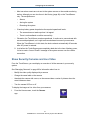
Content Area
The content area contains the interactive functionality of your TouchScreen. The
TouchScreen apps (widgets) are displayed here. When you use or modify an app, the
menus and tools appear here.
Figure 2-2. Content Area
22
SMCRB5701-Z TouchScreen Security System User Manual
Configuring the TouchScreen
Home Screen
The Home screen is the default interface when you access the TouchScreen screen. Return
to this screen at any time by:
Pressing the Home button at the bottom-center of the TouchScreen.
Touching the Home icon in the top-right of any screen, except the Home
screen.
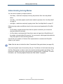
The Home screen displays up to 10 TouchScreen apps at a time. The apps resemble those
installed on a smart phone. If you have more than 10 apps installed on the TouchScreen, the
additional apps appear on additional screens.
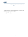
Screen buttons below the apps denote the number of screens the TouchScreen is currently
using to accommodate all the installed apps In Figure 2-3, the two indicators mean the
TouchScreen has two screens to accommodate its installed apps.
Think of the multiple screens as residing next to each other in a line. The green indicator
represents the screen currently displayed.
Figure 2-3. Example of Two Screens Available on This TouchScreen
23
SMCRB5701-Z TouchScreen Security System User Manual
Configuring the TouchScreen
To access another screen of TouchScreen apps:
1. Swipe your finger from right to left across the TouchScreen.
2. To return to a previously viewed screen, sweep your finger from left to right across the
TouchScreen.
24
SMCRB5701-Z TouchScreen Security System User Manual
Configuring the TouchScreen
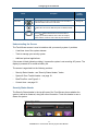
TouchScreen Apps (Widgets)
TouchScreen apps are applications that provide additional functionality through the
TouchScreen. The Security and Settings apps are non-optional apps. The Cameras,
Thermostats, and Lights apps are automatically installed if you have those devices
connected to your system. All other apps can be fully managed from the TouchScreen using
the Settings app:
To install available apps to the TouchScreen, see page 26.
To reposition the order that apps are displayed in the Home screen, see page 27.
To uninstall apps from the TouchScreen, see page 28.
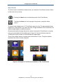
The following summary describes the available apps.
Select the Security app to
view options related to
arming or disarming the
system, enabling or
disabling security zones,
and viewing history logs’
recent security zone events.
Select the Thermostats app
to view the current state of all
your thermostats.
Select the Settings app to
access tools to modify the
TouchScreen
configurations.
Select the Lights app to view
the current state of all your
light control devices.
Select the Cameras app to
view a live feed of all the
cameras in your security
system.
25
SMCRB5701-Z TouchScreen Security System User Manual
Configuring the TouchScreen
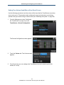
Installing TouchScreen Apps
You can install custom apps on your TouchScreen.
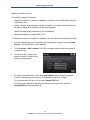
To install an app on the TouchScreen:
1.
From the Settings app (see ―Configuring
the TouchScreen‖ on page 14), touch
Widgets > Add a Widget.
A list of apps available for installation
appears.
2.
Touch the Up and Down arrows on the
scrollbar to expose additional apps.
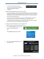
3.
Touch the app you want to install and touch
Next. The app to be added appears, along
with a view of the initial screen of the app.
26
SMCRB5701-Z TouchScreen Security System User Manual
Configuring the TouchScreen
4.
Touch Next. The TouchScreen displays the
following confirmation:
The [name] widget was installed successfully.
5.
Touch Next to redisplay the list of apps available for installation.
Note: The TouchScreen will not receive your updates if your device does not currently have
broadband access. When broadband access is restored, the new apps are installed.
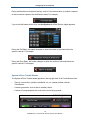
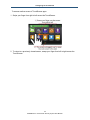
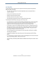
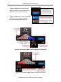
Reordering Apps on the Home Screen
System apps and device apps are always displayed first in the Home Screen. Custom apps
are displayed, by default, in the order they were installed. The Home screen can
accommodate up to 10 apps. Additional apps are displayed on subsequent screens.
Figure 2-4. Examples of Apps on Home Screen
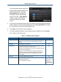
To change the order of the apps displayed in the Home screen:
1.
From the Settings app (see ―Configuring
the TouchScreen‖ on page 14), touch
Widgets > Reorder Widgets.
27
SMCRB5701-Z TouchScreen Security System User Manual
Configuring the TouchScreen
A list of installed apps appears.
2.
Touch the Up and Down arrows on the
scrollbar to expose additional apps.
3.
Touch Up to move the app higher in the sequence of displayed apps, or Down to move it
lower. If you touch To Top, the app appears first in the list of sortable apps.
4.
When the apps are in the desired order, touch Save Widget Order.
5.
Touch Return to Menu to return to the Settings screen.
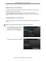
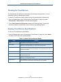
Uninstalling Apps
Custom apps can be uninstalled from the TouchScreen. System apps (Security and
Settings) and device apps (such as Cameras or Thermostats) cannot be uninstalled.
To uninstall an app:
1.
From the Settings app (see ―Configuring
the TouchScreen‖ on page 14), touch
Widgets > Remove a Widget.
28
SMCRB5701-Z TouchScreen Security System User Manual
Configuring the TouchScreen
A list of installed apps appears.
.
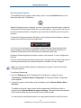
2.
Touch the Up and Down arrows on the
scrollbar to expose additional apps.
3.
Touch the app you want to uninstall and
touch Next. The app being removed is
displayed.
4.
Touch Next. The TouchScreen displays the confirmation message:
The [name] widget has been removed.
5.
Touch Next to redisplay the list of installed apps.
29
SMCRB5701-Z TouchScreen Security System User Manual
Configuring the TouchScreen
Low Power Mode
The TouchScreen is powered by a back-up battery and A/C power. When A/C power is lost,
the TouchScreen places itself in Low Power mode.
Warning: Low Power Mode is an emergency backup mode that ensures your security system
will continue to communicate alarms during unforeseen power outages. During Low Power
Mode, your system loses remote control functionality and only broadcasts major system
events such as alarms.
If A/C power to the TouchScreen is lost, the following occurs:
1. The Quickarm button LED
and the Panic Alarm button LED
go dark.
2. The TouchScreen stops communicating over broadband with the central-monitoring
station and the system servers. If the premise loses power, the router will be down as
well.
3. The TouchScreen stops sending heartbeat signals to the system servers over
cellular.
4. The TouchScreen reports an AC Power Loss trouble in the Trouble Header.
5. If connectivity is available , the TouchScreen tries to send an AC Power Loss
message to the system servers over a cellular connection. If the system servers
receive the message, the Subscriber Portal and other mobile devices report AC
Power Loss trouble and will never report a Connectivity Loss trouble messages for
as long as Low Power Mode continues.
Note: The Subscriber Portal and mobile devices might eventually report a loss of broadband
and cellular connectivity if the AC Power Loss message was not received for some reason. In
this case, they will not report AC Power Loss trouble.
6. Fifteen seconds after the attempt to send the message, the TouchScreen screen
goes dark.
7. While in Low Power Mode:
–
Tapping the screen ―wakes up‖ the TouchScreen temporarily to display the Home
screen; however you will not be able to use any TouchScreen apps that need to
communicate with remote sources. For example, you will not be able to use the
News app or Photo app at all.
–
The TouchScreen stays awake only long enough to continue communicating with the
sensors and monitoring for other events.
30
SMCRB5701-Z TouchScreen Security System User Manual
Configuring the TouchScreen
–
–
–
Most non-alarm events are not sent to the system servers or the central-monitoring
station, although you can view them in the History (page 48) on the TouchScreen
only. The exceptions are:
Alarms
Arming the system
Disarming the system
If back-up battery power drops below the required operational levels:
The screen does not wake up when it is tapped.
There is no broadband or cellular connectivity.
Otherwise, the TouchScreen remains operational. It continues to communicate with
sensors and peripherals, so it might emit sounds based on security zone events.
When the TouchScreen is in this state, the device reboots automatically 90 seconds
after A/C power is restored.
8. Just before the TouchScreen goes completely dead due to the loss of battery power,
it tries to send a ―Loss of Power‖ message to the system servers over the cellular
connection.
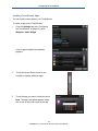
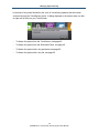
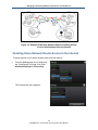
Show Security Cameras and Live Video
From the TouchScreen, you can display an overview of all the cameras in your security
system.
See ―Managing Cameras‖ on page 49 for information about how to:
Modify the video quality displayed by a camera
Change the name label on the camera
Associate the camera with a zone, so the camera takes a series of pictures when the
zone initiates an alarm
Turn the camera LED on or off
To display the images or live video from your cameras:
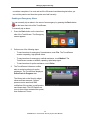
1.
From the Home screen, touch the Camera
app.
31
SMCRB5701-Z TouchScreen Security System User Manual
Configuring the TouchScreen
Images of all the camera views are
displayed and updated every five seconds.
If there is only one camera attached to the
security system, the camera view displays
live video.
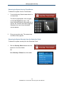
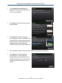
2.
To view live video from a camera, tap an
image.
3.
If the TouchScreen loses connectivity with
the camera while displaying live video from
it, the following message is displayed.
4.
Touch OK to close the message manually. (Or wait for the video to be restored, which
closes the message automatically.)
32
SMCRB5701-Z TouchScreen Security System User Manual
3 Managing System Security
The chapter describes key concepts and management operations for your security system.
The topics covered in this chapter are:
Understanding Arming Modes (page 34)
Arming and Disarming the System (page 37)
Managing Sensors (page 46)
Managing Cameras (page 49)
Editing Key Fobs (page 55)
Testing Your Alarms (page 55)
33
SMCRB5701-Z TouchScreen Security System User Manual
Managing System Security
Understanding Arming Modes
You can arm the system by multiple scenarios:
Arm Away – used when everybody is leaving the premises. See ―Arm Away Mode,‖
below.
Arm Stay – used when people are still active inside the premises. See ―Arm Stay Mode‖
on page 36.
Arm Night – used when everybody is going to bed. See ―Arm Night Mode‖ on page 37.
Different arming modes use different rules for when sensors are tripped and for Entry/Exit
delays.
An Exit delay is a short period of time after the system is armed for you to leave the
premises (default 60 seconds).
An Entry delay is a short period of time after a sensor is tripped at an Entry/Exit door if
the system is armed (default 30 seconds). You must enter a valid keypad code within the
Entry delay period to avoid sounding an alarm.
Consult with your installer or Customer Care representative to customize the Entry/Exit
delays on your system.
Note: After the alarm is faulted the Alarm Transmission Delay period starts (see page 38).
If the central system loses all connectivity with your TouchScreen in the Armed state during
the Entry Delay period, an alarm is sent to the central-monitoring station immediately. This
prevents an intruder from trying to stop an alarm by destroying the TouchScreen. For more
information, see ―Protecting Against Smash-and-Grab Attacks‖ on page 46.
34
SMCRB5701-Z TouchScreen Security System User Manual
Managing System Security
Arm Away Mode
The Arm Away mode is used when everyone is leaving the house. When Arm Away mode is
activated:
The alarm trips immediately if a monitored perimeter zone (non-entry/exit door or
window) is opened.
Interior motion detectors are armed.
Entry/Exit zones start an Entry Delay.
Exit Delay starts when the system is armed.
The following Entry/Exit Delay rules apply to Arm Away mode:
When armed, the system beeps every second to announce it is in the Exit Delay period.
During the last 10 seconds of the Exit Delay state, the system beeps two times per
second.
If an entry/exit zone is opened, the Entry Delay period emits a beep every second. The
system beeps twice per second during the last 10 seconds of the Entry Delay period.
The keypad code must be entered during this period to avoid sounding an alarm.
A numerical countdown timer on the TouchScreen shows the amount of time remaining
in the Exit Delay.
If an entry/exit zone is faulted, restored, and then faulted again before the Exit Delay
ends, the Exit Delay restarts. This only occurs once.
If no Entry/Exit Zone opens and closes during the Exit Delay, the Arming Mode reverts to
Armed Stay.
After Exit Delay, the Security Status header is relabeled Armed Away and emits 2 short
beeps.
If an Entry/Exit zone is opened, the Entry Delay period starts with a beep every second.
The system beeps twice per second during the last 10 seconds of the Entry Delay
period. The keypad code must be entered during this period to avoid sounding an alarm.
During the Entry Delay period, the motion detectors do not log events.
35
SMCRB5701-Z TouchScreen Security System User Manual
Managing System Security
Arm Stay Mode
The Arm Stay mode is used to arm the system when there are people in the premises.
When Arm Stay is activated:
The alarm trips immediately if a monitored perimeter zone (non-entry/exit door or
window) is opened.
Interior motion detectors are not armed.
Entry/Exit zones start an Entry Delay.
Exit Delay starts when the system is armed.
Exit Delay does not beep and is twice as long as Alarm Away mode.
The following Entry/Exit Delay rules apply to Arm Away mode:
If an entry/exit zone is opened, the Entry Delay period beeps every second. The system
beeps two times per second in the last 10 seconds of the Entry Delay period. The
keypad code must be entered during this period to avoid sounding an alarm.
If the system is armed, the Exit Delay period starts, but there is no beep during the Exit
Delay period, as there is in Arm Away mode. The Exit Delay period is the time between
the system being armed and the alarms actually being activated. This gives the user
time to leave through an entry/exit security zone.
The Exit Delay period is twice as long as for Arm Away mode, and there is no audible
alert during the countdown.
A numerical countdown timer shows the amount of time remaining in the Exit Delay
period.
If an entry/exit zone is faulted, restored, and then faulted again prior to the end of the exit
delay, the Exit Delay restarts. This only occurs once.
After Exit Delay, the Security Status header is relabeled Armed Stay and sounds 3 short
beeps.
36
SMCRB5701-Z TouchScreen Security System User Manual
Managing System Security
Arm Night Mode
Arm Night mode is used when everyone is going to bed. This mode works the same as Arm
Stay, except there is no Entry Delay period. If an entry/exit zone is opened, an alarm sounds
immediately.
This mode has an Alarm Transmission Delay period (see ‖Disarming the System‖ on page
38). It also has an Exit Delay period that works the same as in Arm Stay mode (see ―Arm
Stay Mode‖ on page 36).
Arming and Disarming the System
The Security status of your TouchScreen is displayed in the Security Status header. For
more information, see Table 3-1.
Table 3-1. Security Status Header Armed/Disarmed States
State
Description
The Security Status header displays this message when the status
is “Armed”. Click to disarm the system.
The Security Status header displays this message when the status
is “Disarmed”. Click to arm the system.
37
SMCRB5701-Z TouchScreen Security System User Manual
Managing System Security
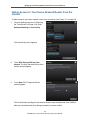
Disarming the System
When you enter an armed premises, an Entry Delay period starts:
The System Status Header changes to announce the number of seconds before the
system is armed. For example:
The Security app screen shows the camera associated with the security zone where you
entered the premises. If no camera is associated with that zone, the default camera is
used.
The TouchScreen beeps once every second. During the last 10 seconds, it beeps twice
a second.
If a valid keypad code is not entered when the Entry Delay period ends, an alarm sounds.
From the time an alarm sounds or starts silently, you have a default time of 30 seconds to
enter a valid keypad code to disarm the system and prevent an alarm from being sent to the
central-monitoring station. This is called the Alarm Transmission delay or the Abort Window.
The Alarm Transmission Delay is a required period that prevents a report to the central
station during an alarm that was triggered innocently.
Emergency alarms (see page 45) and smoke alarms are reported without an Alarm
Transmission delay or an Entry Delay. Consult Customer Care to understand the number of
seconds configured for the Alarm Transmission Delay in your system. After the Alarm
Transmission Delay period, you still have 5 minutes to disarm the system. If you do this and
a monitoring operator has not contacted you yet, central monitoring is notified that you
cancelled the alarm. When the Alarm Transmission delay period ends, the monitoring
operator tries to contact the persons on your Emergency Dispatch list in the order you have
determined. This list is maintained in the Subscriber Portal. The monitoring operator will ask
for the secret word in ensure the person is a valid Emergency Dispatch contact.
Depending on the procedures determined by your service provider, the monitoring operator
might attempt to contact you through the TouchScreen device itself. In this case, there will
38
SMCRB5701-Z TouchScreen Security System User Manual
Managing System Security
be a series of ring tones followed by the voice of a monitoring operator that will contact
someone through the TouchScreen device. A dialog displayed in the screen alerts you that
an open call is active on your TouchScreen.
To disarm the system from the TouchScreen, see page 40.
To disarm the system from the Subscriber Portal, see page 40.
To disarm the system with a key pad device see page 90.
To disarm the system with a key fob, see page 93.
39
SMCRB5701-Z TouchScreen Security System User Manual
Managing System Security
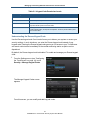
Disarming the System from the TouchScreen
To disarm the system from the TouchScreen:
1.
Touch the Security Status header when it is
in Armed state.
The Security app appears, with a keypad
and the Arm System tab open. If the
sensor that was tripped is associated with a
camera, the view from that camera appears.
Otherwise, the view is from the default
camera appears.
.
2.
Enter your security code. The camera view
and Alarm History appear.
Disarming the System Remotely from the Subscriber Portal
To disarm the system remotely from the Subscriber Portal:
1.
Click the Security Status header when the
system is in the Armed state.
OR
Select Security > Disarm from the toolbar.
40
SMCRB5701-Z TouchScreen Security System User Manual
Managing System Security
2.
When the following dialog appears, enter your
keypad code.
3.
Click Disarm. The Security Status Header
displays a countdown and the Security Status
Header changes to show the system is
disarmed. There is no Entry Exit.
Arming the System
There are several ways to arm the system.
To arm the system from the TouchScreen, see the procedure below.
To arm the system from the Subscriber Portal, see page 42.
To arm the system with a key pad device, see page 89.
To arm the system with a key fob, see page 93.
To quickarm the system, see page 44.
To cancel the arming process, see page 43.
Arming the System from the TouchScreen
To arm the system from the TouchScreen:
1.
.
Touch the Security Status header when it is
in Disarmed state.
The Security Options screen appears, with
a keypad and the Arm System tab open.
41
SMCRB5701-Z TouchScreen Security System User Manual
Managing System Security
2.
Touch an Arming mode and enter your
security code. The Security Status header
changes to display an Exit Delay
countdown.
Observe the following guidelines when arming the system:
If you select Arm Away mode, you have until the Exit Delay is over to exit the premises.
Otherwise, the system is automatically armed in Arm Stay mode. There is still an Exit
Delay period for the other Arming modes as well, but they do not require that the door
open and close during the period.
If you open and shut an Entry/Exit door during the Exit Delay and then re-enter the
premises, the Exit delay restarts at 120 seconds. It only does this one time.
If an Entry/Exit door is left open at the end of Exit Delay, the Entry Delay immediately
starts and, if the system is not disarmed, an alarm will sound.
Arming the System Remotely from the Subscriber Portal
To arm the system remotely from the Subscriber Portal:
1.
Click the Security Status header when the
system is in the Disarmed state.
OR
Select Security > Arm from the toolbar.
2.
When the following dialog appears, enter
your keypad code.
42
SMCRB5701-Z TouchScreen Security System User Manual
Managing System Security
3.
Select whether any of the monitored security zones will be turned off (bypassed) or
turned on (armed).
4.
Select the Arming Mode by clicking Arm Stay, Arm Away, or Arm Night (see
―Understanding Arming Modes‖ on page 34).
5.
Click Arm Now. The Security Status Header
shows a countdown for the Exit Delay period.
When the system is armed, the Security
Status Header immediately changes to show
that state.
Canceling the Arming Process
If you arm the system in Arm Away or Arm Stay mode, the Security Status header shows a
countdown of the number of seconds until the Exit Delay is over. You can choose to cancel
the arming process.
To cancel the arming process:
1.
Touch the Security Status header while it
shows a countdown. The Security app is
displayed, with a keypad and the Arm
System tab open.
2.
Enter your security code to stop the arming
process.
43
SMCRB5701-Z TouchScreen Security System User Manual
Managing System Security
Quickarming the System
To immediately arm the system in Alarm Away mode, touch the Quickarm button on the
lower front side of the TouchScreen.
When the Quickarm button is pressed, you have 10 seconds to cancel this action. After that,
a 60-second Exit Delay begins to allow you to exit the premises. You must wait until the end
of the 10-second countdown is complete to open and close an Exit/Entry door to leave the
premises.
To cancel the Quickarm during the Exit Delay, touch the System Status Header to display a
Keypad screen and then enter your keypad code.
If a Turned On security zone is not completely closed when the 10-second confirmation
period completes, the Quickarm operation is canceled. If the Entry/Exit doorway is not
completely closed at the end of the Exit Delay, the Quickarm action fails.
By default, Quickarming does not require a security code; however, it can be configured to
require it.
If you do not exit through an entry/exit security zone, the system arms in Alarm Stay mode. If
a non-entry/exit security zone is opened during the countdown, an alarm is tripped.
Note: Your service provider might have configured your system to omit the 10-second
confirmation period.
To configure Quickarming:
1. From the Settings app (see ―Configuring the TouchScreen‖ on page 14), select
Touchscreen > Quickarm Button Configuration. The Quickarm Button Configuration
screen appears.
2. To arm the system in Alarm Away mode immediately, select Quickarm Button Starts
Quickarm.
To display the Security Options screen with a keypad when the Quickarm button is
pressed, select Quickarm Button Prompts for Arming. This option makes the Quickarm
button work the same way as touching the Security Status header.
You cannot have a door/window sensor in the open position when the initial 10-second
44
SMCRB5701-Z TouchScreen Security System User Manual
Managing System Security
countdown completes. You must wait until the 60-second countdown begins before you
can exit the premise and have the system arm itself correctly.
Sending an Emergency Alarm
You can manually trip an alarm in the event of an emergency by pressing the Panic button
(
) on the lower front side of the TouchScreen.
To manually trip an alarm:
1.
Press the Panic button on the lower front
side of the TouchScreen. The Emergency
screen appears.
2.
Perform one of the following steps:
3.
To send an alarm for emergency fire assistance, touch Fire. The TouchScreen
sounds a repeating, high-pitched chime.
To send an alarm for emergency medical assistance, touch Medical. The
TouchScreen sounds an audible, repeating, triple beep signal.
To send an alarm for police assistance, touch Police.
The TouchScreen initiates an audible
alert to central monitoring for police
assistance. The TouchScreen displays a
Police Panic In Progress alert.
The History tab on the Security widget
shows an alarm was sent. Contact
persons receive email and SMS
notifications if the system is configured to
send these alerts. The LED flashes red
once to show it has contacted the system,
then flashes red 7 times
45
SMCRB5701-Z TouchScreen Security System User Manual
Managing System Security
Protecting Against Smash-and-Grab Attacks
Your security system communicates continuously (via broadband and cellular) with the
monitoring servers. There is always the possibility that an intruder will try to defeat your
security system by breaking into the premises and destroying the TouchScreen. However,
this is futile. Central monitoring contacts the authorities immediately if both of the following
happens while the system is armed:
The perimeter sensor is faulted or the system goes into Entry Delay (see ―Understanding
Arming Modes‖ on page 34).
Total communication with the TouchScreen is lost.
Managing Sensors
You cannot add or delete the sensors in your Security system, but you can control how they
appear in reports and tools in your TouchScreen and the Subscriber Portal.
Specifically, you can:
Have a sensor not monitored when the system is armed - see page 46.
View your security zone event history - see page 48.
Change the order that security zones are listed in the TouchScreen - see page 49.
Disabling a Sensor
You can turn off a zone and exempt that zone from being monitored when the system is
armed. This is useful during periods when a sensor is being repaired. You can only turn off a
zone when the system is disarmed.
The system continues to use the Event History to log the activity of zones that are turned off
(see ―Viewing Your Zone Event History‖ on page 48).
46
SMCRB5701-Z TouchScreen Security System User Manual
Managing System Security
To turn off zones:
1.
Disarm the system (see ―Arming and Disarming the System‖ on page 37).
2.
Touch the Security icon on the Home
screen (see ―Content Area‖ on page 22).
The Arm System tab appears.
OR
Touch the Dashboard tab to view your
cameras and zones. The default camera
appears.
3.
Touch Next Camera to cycle through the other cameras.
For the zone to turn off the zone, touch the Turn Zone Off button.
For the zone to be monitored for alarms, touch the Turn Zone On button.
The buttons toggle between Turn Zone On and Turn Zone Off as you touch them.
The Security Status header reports any zones that are turned off by when the system is
disarmed.
47
SMCRB5701-Z TouchScreen Security System User Manual
Managing System Security
Viewing Your Zone Event History
If something occurs at a zone, the Security system logs an event regardless of whether the
system is armed or the zone is turned off.
To view the Zone Event History:
1.
Touch the Security icon on the Home
screen (see ―Content Area‖ on page
22).
The Arm System tab appears.
2.
Touch the History tab. The Zone Event
History appears.
Table 3-2. Zone Activity Events
Icon
Description
An Open/Closed doorway
/
An Open/Closed window
/
Motion detected / no motion since last detected motion
/
48
SMCRB5701-Z TouchScreen Security System User Manual
Managing System Security
Changing the Order that Security Zones are Listed in the TouchScreen
If you have a lot of sensors, you might have to scroll down to see them all in screens that
manage and report on security zones such as the Arm System tab and the Dashboard tab
of the Security app. For convenience, you can designate more important sensors to always
appear first in the TouchScreen screens.
To change the order that zones are listed in the TouchScreen screens:
1. From the Settings app (see ―Configuring the TouchScreen‖ on page 14), touch Sensors &
Zones > Change Zone Order. The Change Zone List Order screen appears.
2. From this screen, you can move items up and down in all lists that display order. For
example, if you touch To Top in the zone Window, that zone moves from the bottom of the
list to the top.
Managing Cameras
You can have up to six cameras connected to a TouchScreen. Each camera has a name
assigned to it when it is added.
Each camera can be associated with a sensor, so it takes a series of pictures if an alarm is
tripped by the sensor. Alternatively, you can manually take pictures from a selected camera
using the Subscriber Portal. Some brands of cameras also let you enable or disable the
camera LED.
You can choose the video quality used by each camera based on the quality of the Wi-Fi
connection between the camera and your security network.
Note: Camera images are accessible only to the TouchScreen and one camera via the
Subscriber Portal. Service Provider tools do not have access to these images.
49
SMCRB5701-Z TouchScreen Security System User Manual
Managing System Security
Modifying Camera Details
To modify the details of a camera:
Change the name of a camera as it appears in reports on the TouchScreen and in the
Subscriber Portal.
Assign, reassign, and unassign a camera to a sensor, so it takes a series of pictures if
an alarm is tripped by the sensor (see the following page).
Modify the image quality displayed by the TouchScreen.
Determine whether the camera LED is ON.
To change the details of a camera as it appears in the TouchScreen and Subscriber Portal:
1.
From the Settings app (see ―Configuring the TouchScreen‖ on page 14), touch Home
Devices. The Home Devices menu appears.
2.
Touch Cameras > Edit a Camera. The Edit a Cameras screen shows icons for each
installed camera.
3.
Touch the image or label of the
camera to select it. Details of the
selected camera appear.
4.
To rename the camera zone, touch the Camera Name fields to display a keyboard
screen and rename the camera zone. Click Done to accept your changes.
To turn the camera LED on or off, touch the Enable LED field.
To display menu options for assigning the camera to a security zone, touch the
Associated Zone field (see page 52).
50
SMCRB5701-Z TouchScreen Security System User Manual
Managing System Security
To test the upload network speed and
determine the best video quality level
for the current camera, touch the
Video Quality field (see page 53).
The system lets you choose three
levels of live video – High, Medium,
or Low - based on the camera’s
connection speed to the system
servers.
5.
To have the TouchScreen upload a file to the system servers and gauge the amount
of time it takes to receive an acknowledgement, touch Run Speed Test. This allows
the TouchScreen to recommend video quality level.
6.
Touch Next. The Cameras screen reappears.
7.
To modify additional cameras, touch a camera image. Otherwise, touch the Home
icon to return to the main screen.
Table 3-3. Editing Camera Options
Arming Mode
Description
Can Be Modified?
Model
Model ID for the new camera. The camera manufacturer and model information
are sent to the server and logged for inventory reporting and tech support
purposes.
No
Camera Name
Name assigned to a camera device.
Yes
Associated Zone
Default Camera Arming Mode = if any door sensor not assigned to a camera
trips an alarm, this camera takes a series of pictures.
Yes
Unassigned to Zone Arming Mode = this camera is not associated with another
sensor and is not the default camera.
<Security zone name> Arming Mode = this camera is associated with the
selected zone. It takes a series of pictures automatically if the zone trips an
alarm, regardless of whether the alarm is ultimately sent to the centralmonitoring station.
Video Quality
Level of video detail captured by the camera
Enable LED
ON = camera LED light is ON or blinks to show whether the camera is
communicating with the router.
Yes, for some
brands of cameras.
OFF = camera LED does not go ON.
This field is not
shown if this value
cannot be modified.
51
SMCRB5701-Z TouchScreen Security System User Manual
Yes
Managing System Security
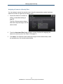
Assigning a Camera to a Security Zone
You can assign a camera to a security zone to have the camera take a series of pictures
whenever an alarm is tripped by the security zone.
1.
Access the details of a camera for
editing, as described starting on
page 50.
The Edit a Camera screen shows a
label and a captured image of all the
camera views.
2.
Touch the Associated Zone fields to display a menu of options for assigning the
camera to a security zone. See Table 3-3 on page 51.
3.
Touch Next. The Cameras screen shows the image of all the camera views (views
are updated every five seconds automatically).
52
SMCRB5701-Z TouchScreen Security System User Manual
Managing System Security
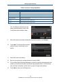
Modifying Video Quality for a Specific Camera
To modify the video quality for a particular camera:
1.
Access the details of a
camera for editing, as
described starting on page
50.
The Edit a Camera screen
shows a label and a
captured image of all the
camera views.
2.
Touch the Video Quality field
to determine the ideal level of
video detail to be captured by
the device.
The Adjust Camera Video
Quality screen appears.
3.
Touch High, Medium, or Low to select the video quality of the camera value for the
network upload capacity (this value must be less than the upload network speed).
4. To update the upload network
speed, touch Run Speed Test
5.
To return to the Adjust Camera Video Quality screen, touch Next.
53
SMCRB5701-Z TouchScreen Security System User Manual
Managing System Security
6.
Touch the appropriate video
quality based on the measured
speed of the Wi-Fi between the
camera and your security
network, and touch Next.
54
SMCRB5701-Z TouchScreen Security System User Manual
Managing System Security
Editing Key Fobs
To edit a key fob:
1.
From the Settings app, touch
Home Devices > Key Fobs.
2.
Touch Edit Key Fob to display
the key fob settings.
3.
From here, you can change the name of the key fob, and enable or disable the key
fob panic button.
Testing Your Alarms
Test your security system at least once per week to ensure that it is in working dependably.
In addition, perform the following steps once a month:
Test your alarm capability
Review the signal strength of the TouchScreen to your Internet router and the cellular
receivers (see ―Viewing Signal Strength‖ on page 60)
Test your connectivity to the Internet and cellular servers (see ―Viewing Signal Strength‖
on page 60)
When testing your alarms, you can choose to report your alarms to central monitoring to
ensure end-to-end integrity. By default, the system lets you test the reliability of your alarms
without sending a signal to central monitoring.
55
SMCRB5701-Z TouchScreen Security System User Manual
Managing System Security
To test your alarms:
1.
From the Settings app (see ―Configuring
the TouchScreen‖ on page 14), touch
Security > Alarm Test.
The Alarm Test Options screen appears.
2.
To have your test alarms reported to
central monitoring, contact your centralmonitoring station and inform them that
you are testing your system.
Then touch Disabled. The button toggles
to Enabled and your test alarms are sent
to central monitoring. (If Enabled already
appears, touching Enabled does not send
your test alarms to central monitoring.)
The Alarm Test Checklist appears.
56
SMCRB5701-Z TouchScreen Security System User Manual
Managing System Security
3.
Be sure all security zones are unfaulted
(that is, doors and windows closed,
motion detectors not showing motion,
etc.). When the security zones are ready
for testing, Ready to Arm appears under
the Arm button.
4.
Touch Arm. Your security system is
armed in special Test mode, with an Exit
Delay of only 10 seconds. Motion sensors
are turned off (not tripping alarms, but
recording events) until an Entry/Exit
security zone is faulted. The Arm button
changes to System Armed.
5.
Touch Next. The Alarm Test screen
appears.
6.
Open and close an Entry/Exit door. The Entry Delay period starts (default is 30 seconds)
and the TouchScreen beeps once per second. The beeping increases to twice per
second during the last 10 seconds of the Entry Delay period. The motion detectors are
turned on.
Note: To mute the siren, touch Mute Siren. However, this is not recommended. Ensuring that
your siren is in working order is an important part of the test.
7.
When the Entry Delay period expires, the
siren sounds (unless you muted it) and
the Entry/Exit zone you faulted is marked
with an alarm tag.
8.
Fault each additional alarm and confirm that it is marked as alarm (see Table 3-4).
57
SMCRB5701-Z TouchScreen Security System User Manual
Managing System Security
Table 3-4. Sensor Testing Operations
Sensor
Testing Process
Door/Window
Open and close the door or window.
Motion Detector
Avoid the motion detector’s view for three minutes after arming the system, then walk in front of it.
Smoke Detector
Press and hold the sensor’s Test button until the siren sounds (approximately 10 seconds).
Glass Break Detector
Use the glass break simulator.
Key Fob
Arm and disarm the system with the key fob.
Key Pad
Arm and disarm the system with the key pad.
The TouchScreen indicates that each
sensor communicated an event to the
TouchScreen and initiated an alarm.
9.
After all the alarms have been faulted and noted by the system, touch Disarm.
10.
Touch Next. The Review Alarms screen
shows a history of the zones in your
system.
11.
Review the zone event history.
12.
Be sure you received any configured alerts via email or SMS.
13.
If you enabled Send Test Alarm Messages, contact the central-monitoring station test
number to ensure that the station received all the generated alarms. If all the alarms
were received successfully, tell the station you are no longer testing alarms.
14.
Touch Next to return to the Settings menu.
58
SMCRB5701-Z TouchScreen Security System User Manual
4 Managing Connectivity Between the TouchScreen
and Monitoring Stations
The TouchScreen communicates constantly with central-monitoring stations via your service
provider’s broadband connection. It also connects to a cellular network if your Internet
connectivity goes down. The TouchScreen can connect to your service provider’s modem
through a cable or Wi-Fi (wireless) connection.
The topics covered in this chapter are:
Viewing Signal Strength (page 60)
Testing Your Connectivity (page 60)
59
SMCRB5701-Z TouchScreen Security System User Manual
Managing Connectivity Between the TouchScreen and Monitoring Stations
Viewing Signal Strength
To view the current signal strength of the TouchScreen’s Wi-Fi connection to your service
provider’s modem:
1.
From the Settings app (see ―Configuring
the TouchScreen‖ on page 14), touch
Advanced Settings > Connectivity >
Wi-Fi & Cellular Signal Strength.
The Wi-Fi and Cellular Signal Strength
screen shows the detected signal strength
of the Wi-Fi connection to the router and
the GPRS/EDGE connection to the
cellular network.
2.
If your Wi-Fi connection is weak, move the TouchScreen closer to the Internet router.
3.
If your cellular signal is weak, move the TouchScreen to another part of the house, where
it can obtain a stronger signal.
Testing Your Connectivity
The TouchScreen can test its connectivity to the Internet and cellular networks. To test the
TouchScreen connectivity:
1.
From the Settings app (see ―Configuring the TouchScreen‖ on page 14), touch
Advanced Settings > Connectivity. The Connectivity menu appears.
2.
Touch Test Connectivity. The
Connectivity Test screen appears.
3.
Touch Next to start the test. The test can take from 30 seconds to four minutes.
60
SMCRB5701-Z TouchScreen Security System User Manual
5 Managing Connectivity Between Home Devices
and the Internet
This chapter describes how to manage the connectivity between the devices in your home
and the Internet. The topics covered in this chapter are:
Overview (page 62)
Granting Home Network Router Access to the Internet (page 63)
Hiding Access to Your Home Network Router from the Internet (page 65)
Managing the Passcodes in your Security System (page 66)
Managing Your Secret Word (page 68)
Viewing Your Security Account Information (page 68)
61
SMCRB5701-Z TouchScreen Security System User Manual
Managing Connectivity Between Home Devices and the Internet
Overview
You home network accesses the Internet through your security network router’s
demilitarized zone (DMZ). The router’s DMZ selectively exposes your home network to the
Internet.
By default, your home network can access the Internet, but entities in the Internet cannot
access computers and devices in your home network. This can be a problem for certain
types of computing and also for using entertainment systems to watch movies, play games,
and so on.
Figure 5-1: Example of Security Network Router Blocking Access
to Your Home Network from the Internet (Default)
You can have your security network router expose your home network to devices on the
Internet (see Figure 5-2). This will not change your security network’s protection from
outside entities. Alternatively, if your home network is exposed to Internet entities, you can
hide it (see page 65).
62
SMCRB5701-Z TouchScreen Security System User Manual
Managing Connectivity Between Home Devices and the Internet
Figure 5-2: Example of Security Network Router Permitting Access
to Your Home Network from the Internet
Granting Home Network Router Access to the Internet
To permit access to your home network router from the Internet:
1.
From the Settings app (see ―Configuring
the TouchScreen‖ on page 214), touch
Advanced Settings > Connectivity.
The Connectivity menu appears.
63
SMCRB5701-Z TouchScreen Security System User Manual
Managing Connectivity Between Home Devices and the Internet
2.
Touch Expose Personal Router to
Internet. The Expose Personal Router to
Internet screen appears.
3.
Touch Next. The Personal Router Setup
screen appears.
4.
Touch Next. The Search for Devices
screen appears. When an available router
is located that is connected to the security
network router by an Ethernet cable, the
Located Devices screen shows the
available routers by their MAC addresses.
5.
Touch the MAC address of the router that needs to be exposed to the Internet.
6.
Touch Next. The Configured Router
screen appears. The TouchScreen
configures the security network router to
expose the selected router, and the home
network devices connected to it, to the
Internet.
64
SMCRB5701-Z TouchScreen Security System User Manual
Managing Connectivity Between Home Devices and the Internet
Hiding Access to Your Home Network Router from the
Internet
To hide access to your home network router from the Internet (see Figure 5-1 on page 62):
1.
From the Settings app (see ―Configuring
the TouchScreen‖ on page 214), touch
Advanced Settings > Connectivity.
The Connectivity menu appears.
2.
Touch Hide Personal Router from
Internet. The Hide Personal Router from
Internet screen appears.
3.
Touch Next. The Configured Router
screen appears.
The TouchScreen reconfigures the security network router demilitarized zone (DMZ) to
hide any connected router from being accessed by Internet entities.
65
SMCRB5701-Z TouchScreen Security System User Manual
Managing Connectivity Between Home Devices and the Internet
Managing the Passcodes in your Security System
Your security system provides the following default keypad codes:
Master
Guest (a ―Guest‖ permission-level)
Duress (see ―Understanding the Duress Keypad Code‖ on page 67)
For more information. see Table 5-1 on page 67.
Managing Keypad Codes
To manage your keypad code:
1.
From the Settings menu (see ―Configuring
the TouchScreen― on page 14), touch
Security > Manage Keypad Codes.
The Manage Keypad Codes screen
appears. From this screen, you can
modify keypad codes or add new ones.
2.
To add a new keypad code, from the Manage Keypad Codes screen, touch Add
Keycode. The Add Keypad Code screen appears.
3.
To modify a keypad code, from the Manage Keypad Codes screen, touch Edit. The Edit
Keypad Code screen appears. (You cannot change the Permissions level of a keypad
code.)
66
SMCRB5701-Z TouchScreen Security System User Manual
Managing Connectivity Between Home Devices and the Internet
Table 5-1. Keypad Code Permission Levels
Arming Mode
Description
Standard or Guest
User can arm and disarm the system.
Arm Only
User can only arm the system.
Master
User can create, edit, and delete keypad codes, as well as arm and disarm the system. This level
is provided with the system and cannot be added.
Distress
User is granted full access to the TouchScreen. The TouchScreen sends a silent alarm to the
central monitoring station, and the police are dispatched. This level is provided with the system
and cannot be added.
Understanding the Duress Keypad Code
Use the Duress keypad code if an intruder forces you to disarm your system or access your
security settings. In such situations, you enter the Duress keypad code instead of your
keypad code. Entering the Duress keypad code grants you full access to your TouchScreen
and sends a silent alarm immediately to the central-monitoring station so police can be
dispatched.
By default, the Duress keypad code is disabled. To enable and manage your Duress keypad
code:
1.
From the Settings menu (see ―Configuring
the TouchScreen― on page 14), touch
Security > Manage Keypad Codes.
The Manage Keypad Codes screen
appears.
From this screen, you can modify and add key pad codes.
67
SMCRB5701-Z TouchScreen Security System User Manual
Managing Connectivity Between Home Devices and the Internet
Managing Your Secret Word
If an alarm is sent to a central-monitoring station, the station tries to contact you to verify that
a true emergency is occurring. When you answer, the station asks for your secret word as
an additional verification.
To view and modify your secret word:
1. From the Settings menu (see ―Configuring the TouchScreen― on page 14), touch
Advanced Settings > Security Secret Word. The Set Security Secret Word screen
appears.
2. To change the secret word, touch the square Secret Word field. A keyboard appears, so
you can change the secret word.
3. Click Done to save your changes or click Cancel to cancel the change operation.
Viewing Your Security Account Information
To view your account information:
1. From the Settings app (see ―Configuring the TouchScreen― on page 14), touch Advanced
Settings > Account Information. The Validate Account Information screen appears.
2. Go to the Subscribers Portal to modify your account information or contact Customer Care.
3. Touch Next to return to the Settings menu.
68
SMCRB5701-Z TouchScreen Security System User Manual
6 Managing Environmental Devices
This chapter describes how to manage lights and thermostats from one TouchScreen and
Subscriber Portal. The topics covered in this chapter are:
Managing Lights (page 70)
Managing Thermostats (page 73)
69
SMCRB5701-Z TouchScreen Security System User Manual
Managing Environmental Devices
Managing Lights
You can have up to 30 lighting devices connected to a TouchScreen at a time. Each lighting
device has a name assigned to it when it is added and can be designated as dimmable.
Dimming or Turning Off Lights
To dim or turn off a light:
1.
From the Home screen, touch the Lights
app.
The Lighting screen shows controls for
each installed light.
If the ON/OFF button = ON, the light’s
power is turned on.
If the button = OFF, the light’s power
is turned off.
2.
Touch the ON/OFF button to turn the light
off.
3.
Touch the minus (-) or plus (+) button to decrease or increase the Dim level of the light. If
you set the Dimmer control to 0%, the light will not light even when it is turned on.
You can perform the following operations:
Modify lighting devices (page 71)
Add lighting devices (page 72)
Delete lighting devices (page 73)
70
SMCRB5701-Z TouchScreen Security System User Manual
Managing Environmental Devices
Modifying the Details of Your Lights
Use the following procedure to:
Change the name of a lighting device in reports on the TouchScreen and in the
Subscriber Portal.
Set the light to be dimmable.
To dim or turn off a light:
1.
From the Settings app (see ―Configuring the TouchScreen‖ on page2 14), touch Home
Devices. The Home Devices menu appears.
2.
Touch Lighting > Edit Lights. The
Configure Lighting Devices screen shows
icons of each installed light.
3.
Touch the icon for the lighting device you want to modify. Details about the selected
lighting device appear.
4.
Touch the Light Name field to display a keyboard screen to change the label of the
lighting device.
5.
Touch the Dimmable field to use (Yes) or not use (No) the lighting device’s dimming
features if available.
6.
Touch Next. The Configure Lighting Devices screen reappears.
71
SMCRB5701-Z TouchScreen Security System User Manual
Managing Environmental Devices
Adding a Lighting Device
The following procedure describes how to add a lighting device.
Note: To update the firmware on any sensor before adding it to the security system, reset the
sensor to factory defaults before adding it to the SMCRB5701-Z Security, Monitoring, and
Automation Gateway security system. This is essential so that it can receive the necessary
changes to communicate with the TouchScreen.
To add a lighting device:
1.
From the Settings app (see ―Configuring the TouchScreen‖ on page2 14), touch Home
Devices. The Home Devices menu appears.
2.
Touch Lighting > AddLights. The Locating Lighting Devices screen appears.
3.
Touch Next.
4.
Plug the lighting device into a wall socket and secure with a screw. The lighting devices
should be unpaired when they are removed from their packaging. When they are
installed in a socket, the LED flashes three times every five seconds, indicating that the
device is in Search mode and ready to pair with a TouchScreen.
5.
If you have problems pairing a lighting
device, reset it to factory default by
pressing the On/Off button as you plug the
device into the socket.
As lighting devices are found, an icon appears displayed for that device.
6.
When all the lighting devices are found, touch Done. The system notes the number of
devices that were found and paired.
7.
Touch Next. The Configure Lighting Devices screen appears.
8.
Touch a lighting device to configure it, as described on page 71.
72
SMCRB5701-Z TouchScreen Security System User Manual
Managing Environmental Devices
Removing a Lighting Device from the TouchScreen
To remove a lighting device from the TouchScreen:
1.
From the Settings app (see ―Configuring the TouchScreen‖ on page2 14), touch Home
Devices. The Home Devices menu appears.
2.
Touch Lighting > Delete Lights. The Settings screen shows an icon for each connected
lighting device.
3.
Touch the icon for the lighting device you want to remove. The following confirmation
message appears:
Deleting a light device cannot be undone. Are you sure you want
to delete the [lighting device label].
4.
Touch Yes.
Managing Thermostats
You can have up to 30 thermostats connected to a TouchScreen at a time. Each thermostat
has a name assigned to it when it is added and is designated as dimmable or not.
To control the thermostats:
1.
From the Home screen touch the
Thermostats app.
In the Thermostat app, you can set the
mode to Cool, Heat, or Off.
73
SMCRB5701-Z TouchScreen Security System User Manual
Managing Environmental Devices
2.
Toggle the Hold button to maintain the
mode and ignore any other programming
configured on the Thermostat device.
3.
Toggle the Fan button to turn on the blower
all the time, or only when the system is
currently cooling or heating the room.
Figure 6-1. Example of Mode “Cool”/ Readings in Fahrenheit
Figure 6-2. Example of Mode “Heat”/ Readings in Celsius
74
SMCRB5701-Z TouchScreen Security System User Manual
Managing Environmental Devices
The bar range (
) for controlling the thermostat temperature settings is:
9-33 degrees Celsius
51-91 degrees Fahrenheit
Your thermostat device might have a wider range. You can use the increment buttons in the
Thermostat app on your TouchScreen to change the temperature beyond these settings.
75
SMCRB5701-Z TouchScreen Security System User Manual
7 Maintaining and Configuring the TouchScreen
This chapter describes how to configure the TouchScreen to maintain and configure the
TouchScreen. The topics covered in this chapter are:
Rebooting the TouchScreen (page 77)
Recalibrating the TouchScreen (page 77)
Configuring TouchScreen Brightness and Dimming (page 78)
Configuring the Screensaver (page 82)
Configuring Tones and Volume Levels (page 83)
Cleaning the TouchScreen (page 86)
Viewing TouchScreen Specifications (page 86)
76
SMCRB5701-Z TouchScreen Security System User Manual
Maintaining and Configuring the TouchScreen
Rebooting the TouchScreen
If a problem occurs that can be resolved by rebooting the TouchScreen, use the following
procedure to reboot the TouchScreen.
1. From the Settings menu (see ―Configuring the TouchScreen‖ on page 14), touch
Advanced Settings > Reboot Touchscreen. The TouchScreen turns itself off and back
on.
Recalibrating the TouchScreen
Perform this procedure to improve how well the TouchScreen senses when and where you
touch it.
Note: Performing this procedure reboots the TouchScreen automatically.
1.
From the Settings menu (see ―Configuring
the TouchScreen‖ on page 14), touch
TouchScreen > Screen Configuration.
The Screen Configuration menu appears.
77
SMCRB5701-Z TouchScreen Security System User Manual
Maintaining and Configuring the TouchScreen
2.
Touch Recalibrate Touchscreen. The
Recalibrate TouchScreen screen appears.
3.
Touch Recalibrate Touchscreen. The
TouchScreen reboots and the screen
goes black. After a while, a calibration
icon appears in the corner of the screen.
4.
Touch the calibration icon. The icon appears successively in the other three corners and
then in the center of the screen.
5.
Touch the calibration icon each time the calibration icon appears. The TouchScreen
continues to boot.
Configuring TouchScreen Brightness and Dimming
There are several options for configuring the TouchScreen’s screen brightness:
Set the TouchScreen’s default brightness level from level 10 (the brightest and the
default setting) to level 1 (the dimmest). See page 79.
Have the screen dim automatically to a preconfigured setting after a configured period of
inactivity (see page 81).
Have the screen and the TouchScreen LEDs (that is, the
and
buttons) dim
completely automatically each day at a set time, and then brighten at a set time (see
page 93). This is called Night Mode and is different than Arm Night Mode as described
on page 37.
78
SMCRB5701-Z TouchScreen Security System User Manual
Maintaining and Configuring the TouchScreen
Manually Placing the TouchScreen in Night Mode
To place the TouchScreen in Night Mode manually:
1.
Press the Home button
two times
quickly. A confirmation message appears.
2.
To cancel Night Mode, touch the confirmation message.
3.
If you do not tap the confirmation dialog, the screen and
completely
4.
If you touch the screen, it brightens to its default brightness level.
and
Configuring Default Screen Brightness
To configure the default screen brightness:
1.
From the Settings menu (see ―Configuring
the TouchScreen‖ on page 14), touch
TouchScreen > Screen Configuration.
The Screen Configuration menu appears.
79
SMCRB5701-Z TouchScreen Security System User Manual
buttons darken
Maintaining and Configuring the TouchScreen
2.
Touch Screen Brightness. A control lets
you set the brightness level from 1 to 10
(default is 10).
Configuring Automatic Screen Dimming and Night Mode Dimming
You can have the TouchScreen dim to a set level after a period of inactivity. This can be
used instead of a screensaver or along with a screen saver (see ―Configuring the
Screensaver‖ on page 82).
You can also configure the screen for Night Mode and have it dim completely during
configured hours (see page 37). During this time, the
and
buttons also darken
completely.
To configure the TouchScreen to dim after a period of inactivity:
1.
From the Settings menu (see ―Configuring
the TouchScreen‖ on page 14), touch
TouchScreen > Screen Configuration.
The Screen Configuration menu appears.
2.
Touch Automatic Screen Dimming.
Controls appear for setting the automatic
dimming level and the amount of idle time
for the TouchScreen to wait before
dimming.
80
SMCRB5701-Z TouchScreen Security System User Manual
Maintaining and Configuring the TouchScreen
The maximum Idle Timeout is 30 minutes. It decreases in increments of 5 minutes. To have
the screen never dim due to inactivity, set the Dimming Level to 10.
Configuring the Screen to Dim After a Period of Time Elapses (Night Mode)
The following procedure describes how to configure the screen to dim during a set time
period: If you touch the screen, it brightens to its default brightness level. At the set time
range, the screen dims to its lowest setting (1).
1.
From the Settings menu (see ―Configuring
the TouchScreen‖ on page 14), touch
TouchScreen > Screen Configuration.
The Screen Configuration menu appears.
2.
Touch Screen Nighttime Settings. The
following controls appear (see Table 7-1).
Table 7-1. Screen Nighttime Settings Controls
Control
Backlight off at night
Description
Yes = screen dims during the configured time range.
No = screen does not dim during the configured time period. If the screen is configured to dim
after a period of inactivity, it will dim.
Backlight off time
Time the screen automatically dims to level 1.
Backlight on time
Time the screen automatically brightens to default level.
81
SMCRB5701-Z TouchScreen Security System User Manual
Maintaining and Configuring the TouchScreen
Configuring the Screensaver
You can configure the TouchScreen to display a screen saver after the device has been
inactive for some period of minutes.
Alternatively, you can have the TouchScreen dim to a configured level after a period of
inactivity (see ―Configuring TouchScreen Brightness and Dimming‖ on page 78). This feature
can be used instead of or with a screensaver.
To configure the TouchScreen screensaver:
1.
From the Settings menu (see ―Configuring
the TouchScreen‖ on page 14), touch
TouchScreen > Screen Saver
Configuration.
The Screensaver Configuration screen
appears.
2.
Touch the Start Screensaver arrow buttons to select the number minutes of inactivity
that must occur for the TouchScreen screensaver to start. Range is from 5 to 30 minutes,
in 5-second increments.
3.
In the Select Screensaver Widget menu, touch the app that will be used as a
screensaver.
82
SMCRB5701-Z TouchScreen Security System User Manual
Maintaining and Configuring the TouchScreen
Table 7-2. Commonly Used Screensavers
Control
Description
None
Screen never goes to screensaver.
Security Dashboard
Screen displays the Arm System tab from the Security app.
Camera
Displays stills of the cameras attached to the security system (updated every 5 seconds). If there
is only one camera attached to the security system, it displays live video.
Clock
Displays the current time in digital or analog format.
Flickr
Displays a slideshow of photos from your Flickr account.
Configuring Tones and Volume Levels
You can configure the sounds the TouchScreen plays when a security zone is faulted or
cleared. You can also configure the volume at which the TouchScreen sounds are played.
Setting Event Tones
To set the tones that the TouchScreen uses when an event occurs:
83
SMCRB5701-Z TouchScreen Security System User Manual
Maintaining and Configuring the TouchScreen
1.
From the Settings menu (see ―Configuring
the TouchScreen‖ on page 14), touch
TouchScreen > Sound Configuration.
The Sounds Configuration screen appears.
Red icons (for example, for a door being
open) designate the sound played when a
zone is faulted.
Green icons (for example, for a door
being closed) designate the sound played
when a zone is cleared.
2.
To play when a zone is faulted or cleared,
touch a field to display a menu of sounds.
3.
To have the TouchScreen never play a tone when the associated security zone is
faulted. touch Silence.
84
SMCRB5701-Z TouchScreen Security System User Manual
Maintaining and Configuring the TouchScreen
Setting Tone Volume Used When a Zone Event Occurs
Use the following procedure to set the volume of the tones that the TouchScreen uses when
zone events occur. This procedure also configures the ring tone level when a monitoring
operator calls your device during an alarm event (see ―Disarming the System‖ on page 38).
1.
From the Settings menu (see ―Configuring
the TouchScreen‖ on page 14), touch
TouchScreen > Sound Configuration.
The Sounds Configuration screen appears.
2.
Touch the Volume tab. The Volume screen
appears.
3.
From this screen you can configure the TouchScreen tones to be loud or quiet (13 =
loudest, 0 = mute).
85
SMCRB5701-Z TouchScreen Security System User Manual
Maintaining and Configuring the TouchScreen
Cleaning the TouchScreen
The TouchScreen can be hard to clean without accidentally pressing buttons, or even
accidentally arming or disarming the system.
To clean the TouchScreen screen without concern for pressing buttons inadvertently:
1. From the Settings menu (see ―Configuring the TouchScreen― on page 14), select
Touchscreen > Clean Screen. The Clean Screen appears.
2. Touch Clean Screen for 30 Seconds to display the Cleaning screen. You have 30
seconds to clean the TouchScreen, without concern over pressing buttons.
Viewing TouchScreen Specifications
To view your TouchScreen’s specifications:
1. From the Settings menu (see ―Configuring the TouchScreen― on page 14), touch About.
The About This Touchscreen screen appears.
Table 7-3. About This Touchscreen Details
Setting
Description
Version
Current firmware version installed on your TouchScreen.
Wi-Fi IP Address
Internet Protocol address assigned to your TouchScreen by your router to communicate with it
wirelessly. This value might change if you reset your router to factory defaults.
Ethernet IP Address
Internet Protocol address assigned to your TouchScreen by your Internet Service Provider’s
modem to communicate with it directly (not wirelessly). This value might change if you reset your
modem to factory defaults.
CPE ID
Unique identification code for your TouchScreen.
Wi-Fi MAC Address
Media Access Control address of the adapter your TouchScreen uses to connect wirelessly to
your Internet Service Provider.
Ethernet MAC Address
Media Access Control address of the adapter your TouchScreen uses to connect directly (not
wirelessly) to your Internet Service Provider.
Cellular SIM Card Id
Unique identification code used by your TouchScreen’s cellular service provider to connect your
device to the central-monitoring stations when broadband service is unavailable.
86
SMCRB5701-Z TouchScreen Security System User Manual
Appendix A - Using the Key Pad
A key pad is a wireless peripheral that lets you perform certain TouchScreen
functions in additional locations in your premises. For example, you could
install a key pad near a less-used entry or in an upstairs bedroom to ensure
its Emergency Alarm feature is always readily accessible.
Using the key pad, you can:
Check current system status.
Arm the system in Arm Away or Arm Stay mode (see ―Understanding
Arming Modes‖ on page 34 for a description of arming modes).
Disarm the system.
Send a silent panic alarm for police assistance.
87
SMCRB5701-Z TouchScreen Security System User Manual
Using the Key Pad
Mounting the Key Pad
To mount a key pad to the wall:
1.
Use a Phillips screwdriver to remove the faceplate from the front of
the key pad.
2.
Find the four holes behind the circuit board at the back of the device
3.
Place the key pad on the wall where you want it located, then use a pen to mark the
location of the four holes.
4.
Install four screws in the locations you marked on the wall. Do not screw them in all the
way.
5.
Affix the key pad to the installed screws.
6.
Replace the faceplate to the front of the key pad.
88
SMCRB5701-Z TouchScreen Security System User Manual
Using the Key Pad
Changing Key Pad Batteries
To replace the batteries in the key pad:
1.
Use a Phillips screwdriver to remove the screw from the battery
cover in the back of the key pad. Then remove the cover.
2.
Find the two supplied CR2 3-volt lithium batteries and install them positive end up.
3.
Replace the battery cover.
Checking System Status
To use the key pad to check system status, press the
the current status of the security system. The
status of the security system.
button to light the LED to show
button lights as follows to show the current
Green for three seconds = system is disarmed.
Red for three seconds = system is armed.
Orange for three seconds = system is not ready to be armed (for example, a door is
open).
Arming the System
From the key pad, you can arm your system in Arm Away mode or Arm Stay. Arm Night
mode must be performed from the TouchScreen or Subscriber Portal.
Arm Away Mode
Enter a valid key pad code and press the
button to arm the system in Arm Away mode
(no one still in the premises). For an explanation of this arming mode, see ―Arm Away Mode‖
on page 35.
89
SMCRB5701-Z TouchScreen Security System User Manual
Using the Key Pad
The
button turns red for 3 seconds to indicate that the Exit Delay has started (default 45
seconds—TouchScreen beeps during this period). If the system is not ready (because, for
example, a door or window is opened) the button flashes orange seven times.
Arm Stay
Enter a valid key pad code and press the button to arm the system in Arm Stay mode
(there are still people within the premises). For an explanation of this arming mode, see
―Arm Stay Mode‖ on page 36.
The
button turns red for 3 seconds to indicate that the Exit Delay has started (twice as
long as the period configured for Arm Away—up to 120 seconds with no beeping from the
TouchScreen). If the system is not ready (because, for example, a door or window is
opened), the button flashes orange seven times.
Disarming the System
Enter a valid key pad code and press the
button to disarm the system. This Disarm
works the same as if you performed it from the TouchScreen (see ―Disarming the System‖
on page 38).
Sending an Emergency Police Alarm
Press and hold the
and
buttons for about 2 seconds to send a silent alarm to central
monitoring for police assistance.
The
button flashes orange to indicate that the alarm has been sent. The TouchScreen
does not react in any way, nor will any siren sound; however, if you check the History tab on
the Security widget, you can see an alarm was sent. Additionally, contact persons will
receive email and SMS notifications if they are configured to do so.
90
SMCRB5701-Z TouchScreen Security System User Manual
Appendix B - Using the Key Fob
A key fob is a wireless peripheral that lets you perform certain
TouchScreen functions in additional locations in your premises.
Check the current system status (armed, disarmed, or ―not ready‖).
Arm the system in Arm Away mode or Arm Stay mode (for an
explanation of arming modes, see ―Understanding Arming Modes‖ on
page 34).
Disarm the system before entering the premises.
Send a silent panic alarm for police assistance.
91
SMCRB5701-Z TouchScreen Security System User Manual
Using the Key Fob
Changing the Batteries in the Key Fob
To replace the batteries in the key fob:
1.
Holding the key fob in one hand, carefully insert the tip of a
flat-head screwdriver into the casing seam.
2.
Push lightly and twist the screwdriver handle.
3.
Find the supplied CR2032 3-volt lithium battery.
4.
Remove the circuit board and rubber button pad from the key fob casing.
5.
Insert the battery in the battery slot positive side away from the circuit board.
6.
Replace the circuit board in the key fob casing.
Note: You might need to press the
button three times for the battery status to be fully
gathered and reported to the TouchScreen.
Checking System Status
To check system status, press the
button to light the LED to show the current status of
the security system. The LED flashes red once to indicate that it has contacted the system
then:
Lights green for three seconds if the system is disarmed.
Lights red for three seconds if the system is armed.
Lights orange for three seconds if the system is not ready to be armed (for example, a
door is open).
92
SMCRB5701-Z TouchScreen Security System User Manual
Using the Key Fob
Arming the System
From the key fob, you can arm your system in Arm Away mode or Arm Stay. Arm Night
mode must be performed from the TouchScreen or Subscriber Portal.
Arm Away Mode
Press the
button for about 2 seconds to arm the system in Arm Away mode (no one still
in the premises). See page 16 for an explanation of this arming mode.
The LED flashes red once to indicate that it has contacted the system then lights red for one
second. The Exit Delay starts (default 45 seconds—TouchScreen beeps during this period).
Arm Stay
Press the
button for about 2 seconds to arm the system in Arm Stay mode (there are still
people within the premises). See page 18 for an explanation of this arming mode.
The LED flashes red once to indicate that it has contacted the system then lights red for one
second. The Exit Delay starts — this delay is twice as long as the period configured for Arm
Away (up to 120 seconds with no beeping from the TouchScreen).
Disarming the System
Before entering the premises in Armed state, press the
disarm the system without entering the premises.
button for about 2 seconds to
The LED flashes green once to show it has contacted the system, then lights green for 1
second. The system disarms. There is no Entry Delay. Contact persons receive email and
SMS notifications if the system is configured to send these alerts.
Sending an Emergency Police Alarm
Press and hold the
button for 3 seconds to send a silent alarm to central monitoring for
police assistance. The LED flashes orange to indicate that the alarm has been sent. The
TouchScreen does not react in any way; however, if you check the History tab on the
Security widget, you can see that an alarm was sent. Additionally, contact persons will
receive email and SMS notifications if the system is configured to do so.
93
SMCRB5701-Z TouchScreen Security System User Manual
Appendix C - TouchScreen Installation & Maintenance
Battery Requirements
Batteries
Device
TouchScreen
Device Types
Central Controller
Door/ Window Sensor
Type
Quantity
P5 TS
4 Volt Lithium
1
CR2
Motion Detector Sensor
Glass Break Detector
Model
CR123A
Sensors
CR123A
Smoke/Heat Detector
CR123A
Key Fob
CR2032
Key Pad
1
Peripheral
Camera
CR2
3
3 Volt Lithium
1
2
3 Volt Lithium
2
2
N/A (A/C power adapter)
Installation Information
TouchScreen Installation Options
The TouchScreen can be positioned on a flat surface or mounted to the wall. Wherever you
install the TouchScreen:
Be sure it is in a location where its sirens and other audible signals can be clearly heard
by the occupants.
Locate it where someone entering the premises can easily access it to disarm it.
Place the TouchScreen near an unswitched wall outlet (not controlled by a light switch).
Positioning the TouchScreen
The TouchScreen can be positioned on a flat surface. For best results:
Position the TouchScreen on a flat surface that is not subject to vibrations or wobbling.
Be sure the flat surface is not subject to traffic that can topple or bump the TouchScreen.
94
SMCRB5701-Z TouchScreen Security System User Manual
TouchScreen Installation & Maintenance
Do not position the TouchScreen near a cordless phone stand or microwave, as these
devices can interfere with the communication with the sensors.
To position the TouchScreen on a flat surface:
1.
Insert the A/C adapter into the bracket.
2.
Remove the center screw from the wall outlet.
Then plug the TouchScreen’s A/C adapter into
the top plug of the wall outlet and replace the
center screw through the bracket hole.
3.
Use a P1 Phillips screwdriver to install the four
screws for the TouchScreen stand.
4.
Connect the A/C adapter cable to the back of
the TouchScreen, working the cord through the
stand.
If the installation plan does not involve the
TouchScreen connecting to the customer’s
network wirelessly, then connect an Ethernet
cable to the TouchScreen and the security
network router.
95
SMCRB5701-Z TouchScreen Security System User Manual
TouchScreen Installation & Maintenance
Mounting the TouchScreen on the Wall Mount
Rather than placing the TouchScreen on a table, desk, or counter, you can use the wall
mount to mount the device on the wall.
To mount the TouchScreen on the wall:
1.
Insert the A/C adapter into the bracket.
96
SMCRB5701-Z TouchScreen Security System User Manual
TouchScreen Installation & Maintenance
2.
Remove the center screw from the wall outlet.
3.
Plug the TouchScreen’s A/C adapter into the
top plug of the wall outlet, and replace the
center screw through the bracket hole.
4.
Cut a hole in the wall near an unswitched wall
outlet (not controlled by a light switch).
Drill a hole under the cut-out and work the A/C
cable into the hole and out of the cut-out.
97
SMCRB5701-Z TouchScreen Security System User Manual
TouchScreen Installation & Maintenance
5.
Use the supplied screws to secure the wall
mount to the wall over the cut-out.
6.
Attach the TouchScreen to the wall mount by aligning the wall-mount protuberances to
the holes in the back of the TouchScreen.
7.
After attaching the TouchScreen to the wall
mount, slide it down to secure it in place.
98
SMCRB5701-Z TouchScreen Security System User Manual
TouchScreen Installation & Maintenance
Separating the TouchScreen from the Wall Mount
To remove the TouchScreen from the wall mount:
1.
Insert a flat-head screwdriver between the
device and the wall mount at the location
shown in the figure to the right.
2.
Slide the TouchScreen up.
Recommendations for Sensor Installation and Placement
Door/Window Sensors and Glass Break Detectors
Install door/window sensors and/or glass break detectors at every possible location of entry,
both upstairs and down.
Glass Break Detectors
For best detector performance, select a mounting location that is:
Within 7.6 m (25ft) of the protected glass
Within clear view of the protected glass
On the same wall as the protected glass
At least 2 m (6.5ft) from the floor
At least 1 m (3ft) from forced-air ducts
At least 1 m (3ft) from sirens or bells greater that 5 cm (2in.) in diameter
On a window frame if any heavy window covering is present
99
SMCRB5701-Z TouchScreen Security System User Manual
TouchScreen Installation & Maintenance
Avoid mounting the detector in the following locations:
In a corner
On free-standing post or pillars
In rooms with noisy equipment such as air compressors, bells/ door bell, and power tools
In bathrooms (a slamming toilet seat will easily fault a glass break detector)
Motion Detectors
When placing motion detectors, anticipate traffic patterns:
The lanes of traffic most used by people in your home are also those most likely to be
used by intruders
Foyers, stairways, hallways, and entrance-ways are excellent locations for a motion
detector
Do not place motion detectors at the end of hallways where an intruder will be walking
directly toward or away from the detector. For best coverage, mount the motion so that
the likely direction of intruder motion is across the motion detector’s pattern.
A motion detector facing the following can cause false-alarms or failures in detection:
Direct sunlight
Cold drafts
Windows
Uninsulated walls
Heat sources such as fireplaces and heating vents
Moving objects such as fans
Air-conditioning vents
Glass furniture
Obstructions such as curtains, plants, large furniture, and doors
Note: Free-roaming pets pose special problems for motion detectors. Your installer has been
trained to help you configure your installation to address your specific pet needs.
100
SMCRB5701-Z TouchScreen Security System User Manual
TouchScreen Installation & Maintenance
Smoke Detector Installation Recommendations
The National Fire Protection Association (NFPA) recommends the following for the number
and placement of smoke detectors.
Place smoke alarms as follows:
In every bedroom, in hallways, and on every level of the premises, including the attic and
basement.
High on a wall or on a ceiling (because smoke rises).
If a smoke detector is placed on a ceiling, position at least 4 inches (12 cm) from the
wall.
Be careful about placing smoke detectors within 20 feet of a cooking appliance.
Smoke alarms are an important part of a home fire escape plan.
To maintain your smoke detector:
Test alarms at least monthly by pushing the test button.
Replace batteries in all smoke alarms at least once a year. If an alarm ―chirps,‖ warning
the battery is low, replace battery right away.
Replace all smoke alarms when they are ten years old or sooner if they do not respond
properly when tested.
Additionally we recommend that you:
Maintain a 3 foot (about 1 meter) distance from air supply & return vents.
DO NOT install smoke detectors in a garage or near furnaces.
Install at least 6 m (20 ft) away from kitchens or other areas where combustion particles
are present.
Install smoke detectors at least 2.5 m (8ft) away from bathrooms.
DO NOT install in dirty, dusty, or insect infected areas.
DO NOT install near areas fresh air inlets or returns or excessively drafty areas. Heating/
A/C vents, fans, and fresh air intakes can drive smoke away from smoke detectors.
Remember that dead air spaces may prevent smoke from reaching a smoke detector.
101
SMCRB5701-Z TouchScreen Security System User Manual
TouchScreen Installation & Maintenance
Camera Installation Recommendations
Camera views are accessible to TouchScreen users and family members who log into the
Subscriber Portal. When placing cameras, consider whether their mounting location poses
any privacy issues.
System Limitations
Your security system is designed to provide continued protection in the case of a temporary
loss of power or Internet connectivity. Still, no alarm system can guarantee protection from
burglary or fire in every case. Test your system once a week to be sure it is working as
expected (see Testing Your Alarms on page 34). Pay attention to the following:
It is possible to hear the alarms clearly when you are sleeping, or in all parts of the
house?
Are there unprotected points of entry?
Are there locations of the house that are separated from all the smoke sensors by a
closed door?
Are there sensors on all levels of the house?
Have you changed your keypad codes recently to prevent someone from figuring one of
them out?
You are alerted if the security system loses all connectivity to Internet and cellular service;
however, such an event makes it impossible for your system to send alarms during that time.
Your security system might make you eligible for reduced insurance premiums. Still, a
security system is no substitute for insurance, and a security system cannot compensate
you for any loss of life or property. For this reason, all sensible safety precautions for
preventing fire and intruders are still necessary.
Emergency Preparation
Do not wait until an emergency occurs to make a plan. Talk to each other about what each
person should do in an emergency. For example:
Learn your security system. Get to know how to arm and disarm it, and what to do when
the authorities or central monitoring call.
Be sure everyone (who should know) knows the Secret Word, when to use it, and that it
should not be shared.
Understand the difference between your keypad code and the Duress code.
102
SMCRB5701-Z TouchScreen Security System User Manual
TouchScreen Installation & Maintenance
Understand that you should never enter the premises if you hear an alarm. Call police
from a cell phone or a neighbor’s phone.
Make a plan for how to leave the house in the case of an emergency. Establish multiple
routes and consider how the routes should be different based on the emergency.
Save yourself first! Do not stop to rescue any possessions.
Do not open a door if the handle is hot.
Agree on a single outdoor location for everyone to meet.
Call the fire department or police from a neighbor’s phone.
Use the space on the following page to draw or write multiple escape plans for each member
of the family.
Escape Plans
103
SMCRB5701-Z TouchScreen Security System User Manual
Appendix D - Quick-Reference Tables
This appendix provides tables that list the ranges and default settings for features in your
security system.
Feature
Comments
Ranges and Default Settings
Exit Delay
The time allotted for the customer to exit the premises
when the security system is armed;
The Exit Delay for Arm Stay and Arm Night modes is
twice the configured Exit Delay up to120 seconds.
Default: 60 seconds
Range: 30 seconds to 99 seconds
Exit Delay Progress
Annunciation
TouchScreen beeps once per second. Twice/second
during the last 10 seconds.
Disabled for Arm Stay & Arm Away.
This feature is not configurable.
Exit Delay Restart
Entry/Exit zone is faulted, restored and then faulted
again prior to the end of the exit delay, then Exit Delay
restarts.
One time only.
This feature is not configurable.
Exit Error
If an Entry/Exit door is left open at the end of Exit
Delay, the Entry Delay starts and, if the system is not
disarmed, an alarm sounds.
This feature is not configurable.
Unvacated Premises
During Arm Away, if no Entry/Exit Zone opens and
closes during the Exit Delay, the Arming Mode reverts
to Armed Stay.
This feature is not configurable.
Entry Delay
The time allotted for the customer to disarm the system
after tripping an Entry/Exit security zone.
Default: 30 seconds
Range: 30 to 99 seconds
Entry Delay Progress
Annunciation
TouchScreen beeps once per second Twice/second
during the last 10 seconds.
This feature is not configurable.
Disarm
Enter a keypad code to disarm the system.
This feature is not configurable.
Control buttons
= Home button
The functions of these buttons cannot
be changed.
= Quickarm button
= Panic button
104
SMCRB5701-Z TouchScreen Security System User Manual
Quick-Reference Tables
Feature
Comments
Emergency Alarms
(manual alarms)
Ranges and Default Settings
The functions of this button cannot be
changed.
TouchScreen: Press to access Emergency Alarm
options.
Key Fob/Key Pad: Press and hold for 1.5 seconds to
send a panic alarm for police assistance.
System Acknowledgement
When armed, TouchScreen beeps 3 times. If armed by
key fob, key fob’s LED flashes red once and the holds
red for two seconds. When disarmed from the
TouchScreen, beeps once. If disarmed key fob, key
fob’s LED flash green once and then hold green for two
seconds.
This feature is not configurable.
Remote Arming
Using the key fob, system can be armed in Arm Away
mode and Arm Stay mode. Exit Delay period works the
same way as non-remote arming.
The functions of these buttons cannot
be changed.
= Arm Stay Mode
= Arm Away Mode
Remote Disarming
Using the key fob, the system can be disarmed from
outside the premises. There is no Entry Delay.
This feature is not configurable.
= Disarm system
Alarm Transmission Delay
(Abort Window)
Length of time after an alarm sounds for the customer
to enter a valid keypad code to prevent alarm from
being sent to central.
Default: 30 sec.
Range: Minimum is 15 sec. and the
maximum is 45 sec.
Disarming During the Alarm
Transmission Delay
System disarmed by entering a valid keypad code in
the TouchScreen or a keypad. If invalid keypad code
entered, alarm restarts.
This feature is not configurable.
When alarms are successfully
aborted (that is, disarmed during
the Alarm Transmission Delay
period)
If system is disarmed with within the Alarm
Transmission Delay period, no alarm transmission
occurs. Contacts can opt not to receive SMS and/or
email messages notifying them when an alarm was
aborted and that central monitoring was not notified.
By default, Verify contacts are notified
by SMS and email when an alarm is
disarmed during the Alarm
Transmission Delay period. .
Cancel Window
For 5 minutes after the end of the Abort Window,
customer can disarm system to send an Alarm Cancel
to central monitoring.
This feature is not configurable.
Duress Code
A 4-digit code that sends silent alarm immediately.
Otherwise, same as Master keypad code.
Default: Duress Code is disabled.
Initiating Emergency Alarms (aka
manual alarms)
This is a 2-step action from the TouchScreen.
Not configurable.
Cross Zoning
Two security zones that only trip an alarm if they are
both faulted within a configured period of time. Can
only be created after the security zones have been
added in a separate step.
Default: 10 seconds
Range 1 second to 999 seconds.
105
SMCRB5701-Z TouchScreen Security System User Manual
Quick-Reference Tables
Feature
Comments
Ranges and Default Settings
Swinger Shutdown
After the TouchScreen has sent an alarm the set
number of times (trips) to central monitoring, no more
alarms will be sent to central monitoring for 48 hours or
until the security system is disarmed.
Default: 1 trip
Range: 1 to 6 trips
Fire Alarm Verification
When enabled, central only contacts the authorities
when multiple smoke detectors are faulted OR a one
detector is in an alarm for 60 seconds.
Default: Disabled
Call Waiting
Old-fashioned security systems use phone lines to send alarms to central monitoring, so they
require a caution included with their control panels alerting Installer that a call waiting features
can prevent successful connection to the central station.
Since the TouchScreen connects to central monitoring over broadband and cellular, this alert is
not required.
System Test
Perform the system test described under “Testing Your Alarms” on page 55.
Communications
Test the security system to ensure that it is in proper communication with central monitoring
described under “Testing Your Connectivity” on page 60.
Test In Progress
The titles of all alarm test process screens begin with
“Alarm Test”.
Automatic Termination of Test
There are no conditions that would result in the automatic termination of Test mode. The user
must touch the Disarm button on the Alarm Test screen to end the alarm test.
Screen Brightness
The relative brightness of the TouchScreen screen.
Default: 10 (brightest)
Range: 1 to 10
Automatic Screen Dimming
Idle Timeout
Default: 30 minutes
Range: 5 minutes to 30 minutes
(in 5-minute increments)
Dimming Level
Default: 10 (brightest)
Range: 1 to 10
Backlight off at night
Default: No
Range: Yes or No
Backlight off time
Default :12:00 .A.M.
Backlight on time
Default :12:00 .A.M.
Screensaver Configuration
Minutes inactive before screensaver comes on
Default: 30 minutes
Range: 5 minutes to 30 minutes
(in 5-minute increments)
Sound Configuration
Volume control
Button Configuration
Select the colors the Home button displays when the
system is armed, not armed, and not ready to be
armed (for example, a door is open).
Quickarm button configuration
Quickarm Button Starts Quickarm option causes the Quickarm button to arm the system in Arm
Away mode without entering a keypad code.
Quickarm Button Prompts for Arming option causes the Quickarm button to display the keypad
screen for arming
Expose Personal Router to
Internet
Whether the retail router connected to the security
system router is exposed to the Internet
Screen Nighttime Settings
Not configurable.
Default:
Red (armed)
Green (not armed)
Amber (not ready to be armed)
Default: Not exposed
106
SMCRB5701-Z TouchScreen Security System User Manual
Appendix E - Compliances
E.1 FCC Notice
This device has been designed, constructed, and tested with for compliance with FCC Rules
that regulate intentional and unintentional radiators. As the user of this device, you are not
permitted to make any alterations or modifications to this equipment or to use it in any way
that is inconsistent with the information described in this quick-start guide, without the
express written permission of SMC Networks. Doing so will void your warranty to operate
this equipment.
This device complies with Part 15 of the FCC rules. Operation of this device is subject to the
following two conditions:
1. This device may not cause harmful interference, and
2. This device must accept any interference received, including interference that may cause
undesired operation.
The ―IC‖ designation preceding the radio certification number indicates that this device
complies with the Industry of Canada specifications.
E.2 Device Purpose
Fire/Alarm Central Panel
E.3 UL1023 Notice
This device complies with UL1023.
E.4 UL985 Notice
This device complies with UL985.
107
SMCRB5701-Z TouchScreen Security System User Manual
Compliances
E.5 UL1635 Notice
This device complies with UL1635.
E.6 ULC S545 Notice
This device complies with ULC S545.
E.7 UL985 Notice
This device complies with ULC C1023.
E.8 ETL Notice
This device complies with all ETL and ETLC safety requirements.
E.9 Limitations of Security Products
Security products and alarm systems do not offer guaranteed protection against burglary,
fire, or other emergencies. They may fail to warn for diverse reasons, including (but not
limited to): power failure, dead batteries, improper installation, coverage, coverage areas
overlooked during installation, defeat by technically sophisticated intruders, component
failure, or inadequate maintenance. Alarm systems should be checked weekly to ensure that
all devices are working properly.
AN ALARM SYSTEM IS NOT A SUBSTITUTE FOR INSURANCE.
108
SMCRB5701-Z TouchScreen Security System User Manual
Index
A
Alarm Transmission Delay, 38
key pad, 89
Changing the order of security zones in the
TouchScreen, 49
Checking system status
Alarms, 13
testing, 55
key fob, 92
Alarms sent from
key pad, 89
key fob, 93
Cleaning TouchScreen, 86
key pad, 90
Components for security, 12
Connectivity
Arm Away mode, 35
between home devices and Internet, 61
arming with key fob, 93
managing between TouchScreen and Central
Arm Night mode, 37
Monitoring, 59
Arm Stay mode, 36
testing, 60
arming with key fob, 93
Arming and disarming the system, 37
Controls on the TouchScreen, 16
Arming modes, 34
Conventions in this document, ix
Arm Away, 35
D
Arm Night, 37
Arm Stay, 36
Dim screen brightness
Arming the system, 41
after set period elapses, 81
canceling, 43
Disabling sensors, 46
Subscriber Portal, 42
Disarming the system, 38
TouchScreen, 41
Subscriber Portal, 40
using the key fob, 93
TouchScreen, 40
using the key pad, 89
using the key fob, 93
Assigning cameras to security zones, 52
B
using the key pad, 90
Document
conventions, ix
organization, viii
Battery requirements, 94
Door/window sensors, installation and placement,
C
99
Duress keypad code, 67
Cameras
E
assigning to security zones, 52
installation and placement, 102
Emergency
managing, 49
modifying video quality, 53
Canceling arming, 43
Changing batteries
key fob, 92
alarm, 45
Emergency police alarm
using the key fob, 93
using the key pad, 90
109
SMCRB5701-Z TouchScreen Security System User Manual
Index
Emergency preparation, 102
Event tones, 83
connectivity between the TouchScreen and the
central monitoring stations, 59
volume, 85
keypad codes, 66
G
Glass break detectors, installation and placement,
secret word, 68
sensors and zones, 46
Modes for arming, 34
Modifying video quality for a camera, 53
99
Granting home network activity to Internet, 63
Motion detectors, installation and placement, 100
Mounting
H
key pad, 88
TouchScreen, 96
Hiding home network activity to Internet, 65
N
Home device conectivity to Internet, 61
Home network activity to Internet
Night Mode, 79, 81
granting, 63
O
hiding, 65
Home screen, 16
Options for installing TouchScreen, 94
I
P
Installation options for TouchScreen, 94
Internet conectivity to home devices, 61
K
Passcodes, 66
Police alarm
sent from key fob, 93
sent from key pad, 90
Key fob
Positioning the TouchScreen, 94
arming the system, 93
Preparing for emergencies, 102
changing batteries, 92
Q
checking system status, 92
disarming the system, 93
key pad
Quickarming, 44
arming the system, 89
Quick-reference tables, 104
checking system status, 89
R
disarming the system, 90
mounting, 88
Rebooting TouchScreen, 77
Key pad
Recalibrating the TouchScreen, 77
changing batteries, 89
S
Keypad codes, 66
duress, 67
M
Screen brightness, 78
default, 79
dim after set period elapses, 81
Managing
cameras, 49
Screensaver for TouchScreen, 82
Secret word, 68
110
SMCRB5701-Z TouchScreen Security System User Manual
Index
T
Security
components, 12
Testing
zones, 12
Security account information, 68
Security status header on the TouchScreen, 17
Security zones assigned to cameras, 52
Sending emergency alarm, 45
Sending emergency police alarm
alarms, 55
connectivity, 60
Tone volume for events, 85
Tones and volumes for TouchScreen, 83
Tones for events, 83
TouchScreen
key fob, 93
changing the order of security zones, 49
key pad, 90
Sensor installation and placement
cleaning, 86
configuring screen to dim, 81
cameras, 102
door/window sensors, 99
glass break detectors, 99
controls, 16
default screen brightness, 79
device home screen, 16
motion detectors, 100
disarming the system, 40
smoke detectors, 101
event tone volume, 85
Sensor testing, 58
event tones, 83
Sensors
installation options, 94
disabling, 46
managing connectivity with central monitoring
managing, 46
Separating TouchScreen from wall-mount, 99
stations, 59
mounting on a wall, 96
Signal strength, 60
Night Mode, 79
Smash and grab, 34, 46
positioning, 94
Smoke detector
installation and placement, 101
Specifications for TouchScreen, 86
rebooting, 77
recalibrating, 77
screen brightness, 78
Subscriber Portal
screensave, 82
arming the system, 42
disarming the system, 40
security status header, 17
separating from wall mount, 99
overview, 16
specifications, 86
System
System & Zone Trouble header, 18
arming, 41
tones and volumes, 83
canceling arming, 43
TouchScreen, arming the system, 41
disarming, 38
Trouble header messages, 20
quickarming, 44
V
System & Zone Trouble header, 18
System & zone trouble header messages, 20
System limitations, 102
Video quality of camera, 53
System status
Viewing
key fob, 92
TouchScreen specifications, 86
key pad, 89
zone event history, 48
111
SMCRB5701-Z TouchScreen Security System User Manual
Index
W
Zone event history, 48
Zones, 12
Wall-mounting the TouchScreen, 96
managing, 46
Z
Zone activity events, 48
112
SMCRB5701-Z TouchScreen Security System User Manual
20 Mason
Irvine, CA. 92618
U.S.A.
http://www.smc.com
Document number: U/G SMCRB5701-Z rev. 6.0