1
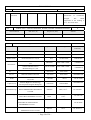
EN 60065:2002
CL.
Requirement of the test
7.1
Result--Remark
Verdict
Table: temperature rise measurements
P
Power consumption in the OFF/stand-by position of the functional
switch (W)…………………………………………………………..
0
Un (V)
In (A)
Pin (W)
Pout (W)
253
1.05→0
232→0
--
Operating conditions
Max Non-clip output power& all ventilations blocked
Temperature rise dT of part/at:
dT (K)
Required dT (K)
Transformer winding
110
135
Switch body (inside)
31
65
PWB near heat sink
88
105
C122 body
47
80
PWB near D161
96
105
Transformer output wire (Secondary)
49
80
Operate panel (front enclosure)
21
65
Top enclosure near heat sink
45
65
Ambient temperature t1 (℃) ………………………………………:
25℃
Ambient temperature t2 (℃) ………………………………………:
25℃
Temperature rise dT of winding:
R1 (Ω)
R2 (Ω)
dT (K)
Required
dT(K)
Insulation
class
A
Remarks: Fuse current is equivalent to input current since current fuse was installed in primary circuit
The thermal link of transformer damaged after 10mins.
—
Page 26 of 26—