1
Driver Overview
2.2.5.30
www.ti.com
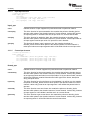
Get MT9T001 Parameters
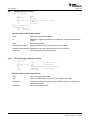
This IOCTL is for backward compatibility. Driver provides functionality to fetch parameters of
MT9T001/MT9T031, if it is a current decoder.
IOCTL: VPFE_CMD_G_MT9T001_PARAMS
It takes void* as an output argument which ultimately points to the structure to the mt9t001_params
structure instance.
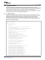
Example:
/* consider that MT9T001 is the current decoder */
mt9t001_params params;
ret = IOCTL(fd, VPFE_CMD_G_MT9T001_PARAMS, ¶ms);
if(ret) {
perror("VPFE_CMD_G_MT9T001_PARAMS\n");
close(fd);
return -1;
}
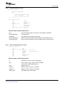
2.2.6
ISR Handling
CCDC has three interrupt registers :- VINT0, VINT1 and VINT2. They can be programmed to occur at any
instance relative to VD signal from the hardware. In the VPFE driver, interrupts are used to mark a frame
capture is complete and schedule next frame for capture and also release the frame to application.
Different interrupts are used for this purpose based on whether the capture happens from output of CCDC
or output of Resizer.
2.2.6.1
Output From CCDC (Data Flow Path 1)
For this, VINT0 is configured to occur at VD. This will generate the frame and field interrupts to align with
the frame and field start. VINT1 is configured to occur at midway in the frame.
For interlaced scan, frame interrupt coincides with the top field (first field) interrupt and bottom field
(second field) interrupt happens at the middle of frame interrupts. For progressive scan, only frame
interrupts happens. VINT1 is configured to happens at midway between frame interrupts for progressive
scans.
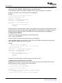
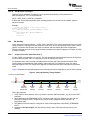
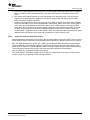
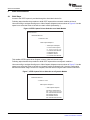
Figure 5 illustrates the relationship between the first interrupt and incoming data in case of frame interrupt.
Figure 5. Interrupt Handling Timing Diagram
CPU Kicks the VPFE Module
frame[n]
top field[n]
1st Frame
Insterrupt
(output start)
bottom field[n]
Bottom
Field
Interrupt
frame[n+1]
top field[n+1]
bottom field[n+1]
2nd
Frame
Interrupt
Bottom
Field
Interrupt
capture frame[n+2]
top field[n+2]
bottom field[n+2]
3rd
Frame
Interrupt
Bottom
Field
Interrupt
time
4th
Frame
Interrupt
This is the sequence:
1. VPFE Capture driver attaches, vpfe_isr() routine to process VINT0 and vdint1_isr() to process VINT1
interrupts.
2. When application call STREAMON IOCTL, vpfe driver calls configure() function from the ccdc hw
interface to configure CCDC. As part of this, CCDC module configures VINT0 and VINT1 (if
progressive scan).
3. The address of the first frame is configured in CCDC when application calls VIDIOC_STREAMON
IOCTL.
4. As shown in the above figure, the first interrupt comes, when CCDC starts storing frame in the
SDRAM.
28
LSP 2.10 Davinci Linux VPFE Capture Driver
SPRUGP6 – June 2009
Submit Documentation Feedback