1
LSP 2.10 Davinci Linux VPFE Capture Driver
User's Guide
Literature Number: SPRUGP6
June 2009
2
SPRUGP6 – June 2009
Submit Documentation Feedback
Contents
1
2
3
Introduction......................................................................................................................... 6
1.1
EVM Configuration for Video Capture .................................................................................. 7
1.2
Supported Features ....................................................................................................... 8
1.3
Constraints ................................................................................................................. 8
Driver Overview ................................................................................................................... 9
2.1
Driver Architecture ........................................................................................................ 9
2.2
Design ..................................................................................................................... 10
Initialization
2.2.2
Opening and Closing of Driver ............................................................................ 11
2.2.3
Buffer Management ......................................................................................... 11
2.2.4
Configuration and Control .................................................................................. 13
2.2.5
IOCTLs Handling ............................................................................................ 16
2.2.6
ISR Handling................................................................................................. 28
Decoders.................................................................................................................. 30
3.1.1
Data Structures and API for Decoder Interface ......................................................... 30
3.1.2
Supported Decoders ........................................................................................ 33
3.1.3
Adding New Decoder Support ............................................................................. 34
User Interface .................................................................................................................... 35
4.1
API ......................................................................................................................... 35
4.2
Data Structures .......................................................................................................... 35
4.3
4.2.1
CCDC Configuration ........................................................................................ 35
4.2.2
CCDC Control ............................................................................................... 35
4.2.3
MT9T001 Parameter Structure ............................................................................ 36
4.2.4
MT9P031 Parameter Structure ............................................................................ 36
4.2.5
TVP5146 Parameter Structure ............................................................................ 37
4.2.6
TVP7002 Parameter Structure ............................................................................ 37
4.2.7
Request Buffer Structure for V4L2 ........................................................................ 37
4.2.8
Buffer Structure for V4L2
4.2.9
Query Capability Structure for V4L2 ...................................................................... 39
4.2.10
Input Structure for V4L2 .................................................................................... 39
4.2.11
Standard Structure for V4L2 ............................................................................... 40
4.2.12
Format Description Structure for V4L2 ................................................................... 40
4.2.13
Format Structure for V4L2 ................................................................................. 41
4.2.14
Query Control Structure for V4L2 ......................................................................... 41
4.2.15
Control Structure for V4L2 ................................................................................. 42
..................................................................................
38
Enumerations and Defines ............................................................................................. 42
4.3.1
5
6
11
Portability .......................................................................................................................... 30
3.1
4
..................................................................................................
2.2.1
Possible Standards for Different Decoders .............................................................. 42
Driver Files ........................................................................................................................ 43
Build and Installation .......................................................................................................... 44
6.1
Build Steps
...............................................................................................................
SPRUGP6 – June 2009
Submit Documentation Feedback
Table of Contents
44
3
www.ti.com
6.2
Installation ................................................................................................................ 45
7
Example Applications ......................................................................................................... 46
4
Contents
SPRUGP6 – June 2009
Submit Documentation Feedback
www.ti.com
List of Figures
1
2
3
4
5
6
7
Simplified Architecture of VPFE ........................................................................................... 6
DM365 EVM Configuration for Video Capture ........................................................................... 7
Basic Architecture of the VPFE Capture Driver.......................................................................... 9
VPFE Capture Driver Detailed Design .................................................................................. 10
Interrupt Handling Timing Diagram ...................................................................................... 28
VPFE Capture Drivers Selection as a Static Module .................................................................. 44
VPFE Capture Drivers Selection as a Dynamic Module .............................................................. 44
List of Tables
1
2
3
Pixel Formats Supported by VIDIOC_ENUM_FMT .................................................................... 19
Parameter Adjustments.................................................................................................... 21
VPFE Capture Driver Files ................................................................................................ 43
SPRUGP6 – June 2009
Submit Documentation Feedback
List of Figures
5
User's Guide
SPRUGP6 – June 2009
LSP 2.10 Davinci Linux VPFE Capture Driver
1
Introduction
VPFE Capture driver is a V4L2 device driver for capturing video frames from a Raw Bayer RGB or Raw
YUV data source.
VPFE Capture driver described in this document is applicable to following DaVinci SoCs:
• DM6446
• DM355
• DM365
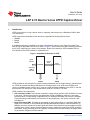
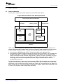
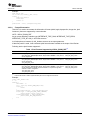
A simplified architecture (simplified for the sake of describing the driver) of the Video Processing Front
End (VPFE) as applicable to the driver is shown in Figure 1. Only functional IPs that are directly controlled
by the VPFE capture driver is shown in the diagram. Please refer respective VPFE Hardware PRG for
more details on the VPFE available on a particular SoC.
Figure 1. Simplified Architecture of VPFE
VPFE
interface
Internal
BUS
CCDC/ISIF
Image
Processing
SDRAM
SDRAM
Raw Bayer
RGB or
YUV data
VPFE provides an input interface for external imaging peripherals such as image sensors, video decoders
etc. VPFE can process Raw Bayer RGB data from an image sensor such as Micron’s MT9T001 and
convert to viewable formats such as UYVY using the image processing hardware in the VPFE. It can also
process Raw YUV data from a video decoder device such as TVP5146 or TVP7002.
VPFE consists of two main blocks:
• CCD controller (CCDC). This has been renamed to Image Sensor Interface (ISIF) in DM365 but refers
to the same. This block pre-process input data before saving to SDRAM or passing it to the Image
processing block. Pre-processing is applicable only for raw Bayer RGB data from a sensor. Examples
of pre-processing includes defect pixel correction, a-law compression, color space conversion, data
formatting etc.
• Image Processing (IMP). This block is responsible for doing image tuning on a raw Bayer RGB data
output from CCDC/ISIF or from SDRAM and upscale/downscale the output to a desired resolution. In
DM6446, this block consists of Preview Engine and Resizer. More features have been added to VPFE
in newer SoCs to help in image processing and the same is renamed to Image Pipe (IPIPE) in DM355
and DM365. Image processing unit has a pipeline of modules each of which modifies the image based
on parameters configured in these modules.
6
LSP 2.10 Davinci Linux VPFE Capture Driver
SPRUGP6 – June 2009
Submit Documentation Feedback
Introduction
www.ti.com
Examples of image tuning modules include White Balance, Noise filter, RGB to RGB converter, Edge
enhancement, Gamma Correction etc. Please refer VPFE hardware user guide for more details on
these modules. Resizer hardware is used to upscale or downscale the image to a desired resolution.
DM6446 has one Resizer output where as in DM355 and DM365, there are 2 Resizers acting on the
same video input (RSZ-A & RSZ-B) there by producing 2 output resolutions. VPFE capture driver
would require image processing unit to do image tuning and for upscale or downscale the image
before being written to SDRAM. For chaining the image processing modules in the data path from
CCDC/ISIF, IPIPE must be configured to work in continuous mode.
VPFE Capture driver can configure VPFE to output data from CCDC/ISIF or from the output of Resizer in
Image Processing Module (Not available on DM6446).
1.1
EVM Configuration for Video Capture
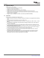
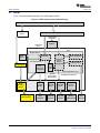
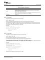
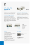
Figure 2 shows the high level configuration of the DM365 EVM that enables video capture using VPFE.
The EVM configuration of DM6446 and DM355 are similar except they do not have TVP7002 to do HD
video capture. VPFE provides a Raw Bayer parallel interface as well as 8/16 bit YCbCr interface to
connect a variety of video peripheral to do video capture. See the VPFE hardware PRG for the interface
specifications. Outputs from various peripherals are multiplexed using CPLD. This allows for the driver to
dynamically connect VPFE to one of the peripheral output to do video capture.
The VPFE capture driver uses this logic to allow dynamic switching of input on request from the
application. The diagram also shows the label used by driver to name each of the input supported by the
input peripherals. Note that RAW is the name used to represent the camera sensor input. Additional
camera inputs are represented by RAW-1, RAW-2 etc….
Figure 2. DM365 EVM Configuration for Video Capture
SVIDEO
TVP5146
COMPOSITE
7002
MUX
VPFE
COMPONENT
SoC
MT9xxxx
RAW
SPRUGP6 – June 2009
Submit Documentation Feedback
LSP 2.10 Davinci Linux VPFE Capture Driver
7
Introduction
1.2
www.ti.com
Supported Features
Following are the main features:
• The driver can be used statically or dynamically.
• Supports one video device (Video0).
• Supports single I/O instance and multiple control instances.
• Supports buffer access mechanism through memory mapping as well as user pointers.
• Supports dynamic switching among input interfaces and various resolutions with some necessary
restrictions wherever applicable.
• Supports capture to SDRAM from CCDC or from Resizer (for DM355 & DM365).
1.3
Constraints
Following are the constraints for the Capture driver:
• Dynamic switching of resolution and dynamic switching of interfaces is not supported when streaming
is on.
• VPFE input/output buffer addresses must be a multiple of 32.
• By default, the driver allocates three buffers for the device. The buffer size is 1920 x 1080 x 2 + 640 x
480 x 2.
• If the application is requesting the user pointer buffer exchange mechanism, then it must request a
minimum of three buffers.
• If you have specified less than three and greater than zero buffers at the time of inserting the driver,
the driver allocates three buffers. If you have specified zero buffers, the driver assumes the use of the
user pointer buffer exchange mechanism.
• If you have specified the buffer size as less than the buffer size required to store an NTSC image at
the time of the insertion of the driver, the driver assumes minimum buffer size.
• If you have specified an incorrect device_type at the time of the insertion of the driver, the driver
assumes zero values for the device_type.
• In continuous mode, with interlaced scan input, only the second field of the input data is used for
capture at Resizer and is scaled up by 2x to preserve the height. So in this mode, the video is
de-interlaced at the driver and hence both fields are not available.
8
LSP 2.10 Davinci Linux VPFE Capture Driver
SPRUGP6 – June 2009
Submit Documentation Feedback
Driver Overview
www.ti.com
2
Driver Overview
2.1
Driver Architecture
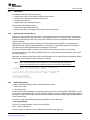
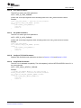
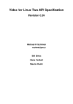
Following block diagram shows basic architecture of the VPFE capture Driver.
Figure 3. Basic Architecture of the VPFE Capture Driver
Capture and Image Processing Application
/dev/video0
/dev/imp_previewer
/dev/imp_resizer
Linux Kernel
Previewer
V4L2
Driver
VPFE
Capture
Driver
Decoder
Driver
Resizer
EVM Board
VPFE Capture driver exposes the capabilities of the hardware to applications using the standard V4L2
interface. Applications will be able to use a V4L2 device (video0) to capture frames from a image sensor
or video decoder connected to VPFE. There are two main data flow paths available in the driver.
1. Input interface to SDRAM through CCDC. This path is available on all supported SoCs.
2. Input interface to CCDC to Image Processing Unit and then output from Resizer. This is available only
on DM355 and DM365. The Resizer on these devices have two outputs: one full resolution image
(RSZ-A) and another smaller resolution image (RSZ-B). Typically, this helps in previewing one image
(usually of a smaller resolution) to a display device and the other (full resolution) for encoding. The
Driver piggy backs the second image at the end of first image in the buffer when the same is
de-queued from the device.
To support the data path 2, capture driver requires that the IPIPE & Resizer hardware are configured to
operate in the continuous mode through the previewer and Resizer device. Previewer driver drives IPIPE
and Resizer driver drives Resizer hardware respectively. Please refer Previewer/Resizer User Manual for
details on these drivers. Once these hardware configuration is complete, Capture driver will be able to use
it do on the fly (continuous mode) image tuning and scaling.
SPRUGP6 – June 2009
Submit Documentation Feedback
LSP 2.10 Davinci Linux VPFE Capture Driver
9
Driver Overview
2.2
www.ti.com
Design
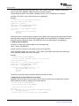
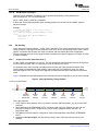
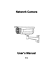
Figure 4 shows the detailed design of the VPFE Capture Driver.
Figure 4. VPFE Capture Driver Detailed Design
Application
Char Driver
Interface
V4L2 Driver Interface
Configuration
and Control
Hardware
Open/Close
Driver
VPFE Capture
Driver
Register Device
Linux
Kernel
Buffer Management
Initialization
Channel and
Device
Specific
Configuration
Unregister Device
Previewer and
Resizer Driver
CCDC
Control and
Configuration
ISR Processing
Device
Global
Data
VPFE Capture/V4L2 Layer
Initialize
Devices with
Default Values
Configuration of Devices
HW Interface Layer
IPIPE
Hardware
Module
IPIPE Hardware
10
CCDC
Module
TVP5146
Driver
TVP7002
Driver
MT9T001
Driver
CCDC
Hardware
TVP5146
Decoder
TVP7002
Decoder
MT9T001
CMOS Sensor
LSP 2.10 Davinci Linux VPFE Capture Driver
INTC
Interrupt
SPRUGP6 – June 2009
Submit Documentation Feedback
Driver Overview
www.ti.com
2.2.1
Initialization
At
•
•
•
•
initialization the driver does the following:
Initializes the CCDC for the default configuration parameters
Allocates vpfe_obj that holds channel configuration
Allocates frame buffers
Registers the driver and platform device
Upon probing, the following are done:
• Initialize the channel data structures
• Allocate video device and register video device with v4l2 framework
2.2.2
Opening and Closing of Driver
The device can be opened using open call from application with device name and mode of operation as
parameters. Application can open the driver in either blocking mode or non-blocking mode. If the channel
is opened in non-blocking mode, driver calls (call to DQBUF) will return to application without waiting for
request completion.
During open(), driver also selects a decoder from the available decoders based on the bootargs and
initialize the same. Using the default standard on the decoder, the channel parameters are configured.
This also sets the channel initialized state if everything is successful.
The driver will support single I/O instance and multiple control instances of each of the channels.
The file descriptor with which VIDIOC_REQBUFS IOCTL is called, will become I/O instance. And rest will
be control instances.
Application can simply call the close function with file handle to close a specific device. Application should
close all the control channels before closing an I/O channel.
Note:
When using data flow path 2 in the capture driver, make sure to open and configure the
previewer and Resizer devices in continuous mode prior to opening the capture device.
/* call to open a video capture logical channel in blocking mode */
video0fd_blocking =open ("/dev/video0", O_RDWR);
/* call to open a video capture logical channel in non-blocking mode */
video0fd_nonblocking =open ("/dev/video0", O_RDWR | O_NONBLOCK);
/* closing of channels */
close (video0fd_blocking);
close (video0fd_nonblocking);
2.2.3
Buffer Management
The driver allows two different types of memory allocation modes:
• Driver buffer mode
• User buffer mode
For driver buffer mode, application can request memory from driver by calling VIDIOC_REQBUFS. In case
of user buffer, application needs to allocate physically contiguous memory using some other mechanism in
user space. In driver buffer mode, maximum number of buffers is limited to VIDEO_MAX_FRAME (defined
in driver header files).
Here are the major steps to be performed by application for buffer allocation:
1. Allocating Memory
This IOCTL is used to allocate memory for frame buffers.
IOCTL: VIDIOC_REQBUFS.
It takes a pointer to instance of v4l2_requestbuffers structure as an argument.
SPRUGP6 – June 2009
Submit Documentation Feedback
LSP 2.10 Davinci Linux VPFE Capture Driver
11
Driver Overview
www.ti.com
The user can specify the buffer type (V4L2_BUF_TYPE_VIDEO_CAPTURE), number of buffers and
memory type (V4L2_MEMORY_MMAP) at the time of buffer allocation.
The file descriptor which will call VIDIOC_REQBUFS IOCTL, will be considered as I/O instance.
Constraint: This IOCTL can be called only once from application.
Example:
/* structure to store buffer request parameters */
struct v4l2_requestbuffers reqbuf;
reqbuf.count = numbuffers;
reqbuf.type = V4L2_BUF_TYPE_VIDEO_CAPTURE;
reqbuf.memory = V4L2_MEMORY_MMAP;
ret = IOCTL(fd , VIDIOC_REQBUFS, &reqbuf);
if(ret) {
printf("cannot allocate memory\n");
close(fd);
return -1;
}
If data flow path 2 is used and Resizer output2 is also enabled, then make sure the frame buffer allocated
should be large enough to hold both images (output1/RSZ-A and output2/RSZ-B). For MMAP, the kernel
allocates memory to hold both outputs. For USERPTR, this is the responsibility of the application.
2. Getting Physical Address
This IOCTL is used to get Physical address of the allocated buffer.
IOCTL: VIDIOC_QUERYBUFS.
It takes a pointer to instance of v4l2_buffer structure as an argument.
User has to specify buffer type (V4L2_BUF_TYPE_VIDEO_CAPTURE), buffer index and memory type
(V4L2_MEMORY_MMAP) at the time of querying.
Example:
/* allocate buffer by VIDIOC_REQBUFS */
/* structure to query the physical address of allocated buffer */
struct v4l2_buffer buffer;
buffer.index = 0; /* buffer index for querying -0 */
buffer. type = V4L2_BUF_TYPE_VIDEO_CAPTURE;
buffer.memory = V4L2_MEMORY_MMAP;
if (IOCTL(fd, VIDIOC_QUERYBUF, &buffer) == -1) {
printf("buffer query error.\n");
close(fd);
exit(-1);
}
The buffer.m.offset will contain the physical address returned from driver.
3. Mapping Kernel Space Address to User Space
Mapping of the kernel buffer to the user space can be done via mmap. User can pass buffer size and
physical address of buffer for getting the user space address.
/* allocate buffer by VIDIOC_REQBUFS */
/* query the buffer using VIDIOC_QUERYBUF */
/* addr hold the user space address */
Int addr;
Addr = mmap(NULL, buffer.size,PROT_READ | PROT_WRITE, MAP_SHARED,
fd, buffer.m.offset);
/* buffer.m.offset is same as returned from VIDIOC_QUERYBUF */
12
LSP 2.10 Davinci Linux VPFE Capture Driver
SPRUGP6 – June 2009
Submit Documentation Feedback
Driver Overview
www.ti.com
2.2.4
Configuration and Control
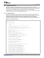
This block is responsible for configuring the CCDC and Image processing hardware for capture.
Application configures and control the hardware using IOCTL calls. This is done prior to starting streaming
on the device and de-queuing the frames. To configure the hardware to implement data flow path #1 and
#2, the driver needs to configures CCDC and Image processing Unit (IPIPE and Resizer).
VPFE capture driver uses CCDC hw interface (defined ccdc_hw_if.h) to configure CCDC and use imp hw
interface (defined in imp_hw_if.h) to configure IPIPE and Resizer.
2.2.4.1
CCDC Configuration
VPFE driver uses functions defined at the CCDC hw interface (ccdc_hw_if.h) to configure CCDC on a
specific SoC. By using these interface functions, the CCDC module conceal the differences in the CCDC
across different SoCs and provides an uniform way to configure the CCDC hardware for capture.
Following are the functions available at the interface. To Support a new SoC, a CCDC module is
developed that implements these functions. All of the CCDC modules are developed using this interface.
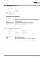
Example 1. CCDC Device Interface
/*
* CCDC device interface
*/
struct ccdc_hw_interface {
/* CCDC device name */
char *name;
/* Pointer to initialize function to initialize ccdc device */
int (*initialize) (void);
/* Set of functions pointers for control related functions.
* Use queryctrl of decoder interface to check if it is a decoder
* control id. If not passed to ccdc to process it
*/
void (*enable) (int en);
/* Pointer to function to enable or disable ccdc */
u32 (*reset) (void);
/* reset sbl. only for 6446 */
void (*enable_out_to_sdram) (int en);
/* Pointer to function to set hw frame type */
int (*set_hw_if_type) (enum ccdc_hw_if_type iface);
/* get interface parameters */
int (*get_hw_if_params) (struct ccdc_hw_if_param *param);
/* Set/Get parameters in CCDC */
/* Pointer to function to set parameters. Used
* for implementing VPFE_S_CCDC_PARAMS
*/
int (*setparams) (void *params);
/* Pointer to function to get parameter. Used
* for implementing VPFE_G_CCDC_PARAMS
*/
int (*getparams) (void *params);
/* Pointer to function to configure ccdc */
int (*configure) (void);
/* Set of functions pointers for format related functions */
/* Pointer to function to try format */
int (*tryformat) (struct v4l2_pix_format *argp);
/* Pointer to function to set buffer type */
int (*set_buftype) (enum ccdc_buftype buf_type);
/* Pointer to function to get buffer type */
int (*get_buftype) (enum ccdc_buftype *buf_type);
/* Pointer to function to set frame format */
int (*set_frame_format) (enum ccdc_frmfmt frm_fmt);
/* Pointer to function to get frame format */
int (*get_frame_format) (enum ccdc_frmfmt *frm_fmt);
/* Pointer to function to set buffer type */
int (*get_pixelformat) (unsigned int *pixfmt);
/* Pointer to function to get pixel format. Uses V4L2 type */
int (*set_pixelformat) (unsigned int pixfmt);
SPRUGP6 – June 2009
Submit Documentation Feedback
LSP 2.10 Davinci Linux VPFE Capture Driver
13
Driver Overview
www.ti.com
Example 1. CCDC Device Interface (continued)
/* Pointer to function to set image window */
int (*set_image_window) (struct v4l2_rect *win);
/* Pointer to function to set image window */
int (*get_image_window) (struct v4l2_rect *win);
/* Pointer to function to set line length */
int (*set_line_length) (unsigned int len);
/* Pointer to function to get line length */
int (*get_line_length) (unsigned int *len);
/* Pointer to function to set crop window */
int (*setcropwindow) (struct v4l2_rect *win);
/* Pointer to function to get crop window */
int (*getcropwindow) (struct v4l2_rect *win);
/* Query SoC control IDs */
int (*queryctrl)(struct
v4l2_queryctrl *qctrl);
/* Set SoC control */
int (*setcontrol)(struct v4l2_control *ctrl);
/* Get SoC control */
int (*getcontrol)(struct v4l2_control *ctrl);
/* Pointer to function to set current standard info */
int (*setstd) (char *std);
/* Pointer to function to get current standard info */
int (*getstd_info) (struct ccdc_std_info *std_info);
/* Pointer to function to set frame buffer address */
void (*setfbaddr) (unsigned long addr);
/* Pointer to function to get field id */
int (*getfid) (void);
/* Pointer to deinitialize function */
int (*deinitialize) (void);
};
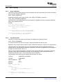
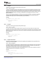
2.2.4.2
Image Processing Unit Configuration
Image processing exposes two interfaces (defined in imp_hw_interface.h) to configure the IPIPE and
Resizer. One interface is used by previewer & Resizer driver. (See Previewer-Resizer Driver User manual
for details). The other interface is used by VPFE capture driver to configure parameters like width, height,
pixel format, resize ratio etc when user invokes ioctls. The IPIPE modules on DM355 and DM365
implements the interface functions. Following are the set of functions exposed by IPIPE module to vpfe
capture driver.
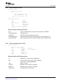
Example 2. Functions Exposed by IPIPE to VPFE Capture Driver
struct imp_hw_interface {
/* Name of the image processor hardware */
char *name;
/* update output buffer address for a channel
* if config is NULL, the shared config is assumed
* this is used only in single shot mode
*/
int (*update_inbuf_address) (void *config, unsigned int address);
/* update output buffer address for a channel
* if config is NULL, the shared config is assumed
*/
int (*update_outbuf1_address) (void *config, unsigned int address);
/* update output buffer address for a channel
* if config is NULL, the shared config is assumed
*/
int (*update_outbuf2_address) (void *config, unsigned int address);
/* enable or disable hw */
void (*enable) (unsigned char en, void *config);
/* enable or disable Resizer to allow frame by frame resize in
* continuous mode
14
LSP 2.10 Davinci Linux VPFE Capture Driver
SPRUGP6 – June 2009
Submit Documentation Feedback
Driver Overview
www.ti.com
Example 2. Functions Exposed by IPIPE to VPFE Capture Driver (continued)
*/
void (*enable_resize) (int en);
/* setup hardware for processing. if config is NULL,
* shared channel is assumed
*/
int (*hw_setup) (struct device *dev, void *config);
/* Get preview irq numbers */
void (*get_preview_irq) (struct irq_numbers *irq);
/* Get resize irq numbers */
void (*get_rsz_irq) (struct irq_numbers *irq);
/* Get configuration state of Resizer in continuous mode */
unsigned int (*get_resizer_config_state) (void);
/* Get configuration state of previewer in continuous mode */
unsigned int (*get_previewer_config_state) (void);
/* Below APIs assume we are using shared configuration since
* oper mode is continuous. These are called from vpfe capture driver
*/
/* Set the input crop window at the IMP interface and IMP */
int (*set_input_win) (struct imp_window *win);
/* Get current input crop window param at the IMP */
int (*get_input_win) (struct imp_window *win);
/* Set interface parameter at IPIPEIF. Only valid for DM360 */
int (*set_hw_if_param) (struct ccdc_hw_if_param *param);
/* Set input pixel format */
int (*set_in_pixel_format) (enum imp_pix_formats pix_fmt);
/* set output pixel format */
int (*set_out_pixel_format) (enum imp_pix_formats pix_fmt);
/* 0 - interleaved, 1 - field seperated */
int (*set_buftype) (unsigned char buf_type);
/* 0 - interlaced, 1 - progressive */
int (*set_frame_format) (unsigned char frm_fmt);
/* Set the output window at the IMP, output selection
* done by out_sel. 0 - output 1 and 1 - output 2
*/
int (*set_output_win) (struct imp_window *win);
/* Get output enable/disable status */
int (*get_output_state) (unsigned char out_sel);
/* Get output line lenght */
int (*get_line_length) (unsigned char out_sel);
/* Get the output image height */
int (*get_image_height) (unsigned char out_sel);
/* Get current output window param at the IMP */
int (*get_output_win) (struct imp_window *win);
/* get maximum output width of rsz-a or rsz_b*/
int (*get_max_output_width) (int rsz);
/* get maximum output height of rsa-a or rsz-b */
int (*get_max_output_height) (int rsz);
};
SPRUGP6 – June 2009
Submit Documentation Feedback
LSP 2.10 Davinci Linux VPFE Capture Driver
15
Driver Overview
2.2.5
www.ti.com
IOCTLs Handling
2.2.5.1
Query Capabilities
This IOCTL is used to identify kernel devices compatible with V4L2 specification and to obtain information
about individual hardware capabilities.
IOCTL: VIDIOC_QUERYCAP
Capabilities can be like video capture (V4L2_CAP_VIDEO_CAPTURE) or streaming
(V4L2_CAP_STREAMING) capabilities.
It takes pointer to v4l2_capability structure as an argument. Capabilities can be accessed by capabilities
field of v4l2_capability structure.
Example:
struct v4l2_capability capability;
ret = IOCTL(fd, VIDIOC_QUERYCAP, &capability);
if(ret) {
printf("Cannot do QUERYCAP\n");
return -1;
}
if(capability.capabilities & V4L2_CAP_VIDEO_CAPTURE) {
printf("Capture capability is supported\n");
}
if(capability.capabilities & V4L2_CAP_STREAMING) {
printf("Streaming is supported\n");
}
2.2.5.2
Input Enumeration
This IOCTL is used to enumerate the information of available inputs (analog interface).
IOCTL: VIDIOC_ENUMINPUT
It includes information like name of input type, supported standards for that input type.
Application will provide the index number for which it wants the information, as part of v4l2_input structure.
Index with value zero indicates first input type of first decoder that has been registered at the time of
module insertion, and after possible inputs for first decoder, next index from application will be mapped to
first input of second decoder, and so on.
That is, if the first registered decoder is TVP5146 and the second is MT9T031, and both are supporting
one type of input; then if the application will pass 0 as an input index, it will enumerate the input of
TVP5146 and for input index 1, it will enumerate the input of MT9T031.
The following are the names used to represent various inputs to the driver:
TVP5146
COMPOSITE and SVIDEO
TVP7002
COMPONENT
MT9T031/MT9T001
RAW
MT9P031
RAW-1
Example:
struct v4l2_input input;
i = 0;
while(1) {
input.index = i;
ret = IOCTL(fd, VIDIOC_ENUMINPUT,&input);
if(ret) {
break;
}
printf("name = %s\n",input.name);
printf("std = %x\n",(unsigned long)input.std);
i++;
}
16
LSP 2.10 Davinci Linux VPFE Capture Driver
SPRUGP6 – June 2009
Submit Documentation Feedback
Driver Overview
www.ti.com
2.2.5.3
Set Input
This IOCTL is used to set input type (analog interface type).
IOCTL: VIDIOC_S_INPUT
In order to accomplish this, driver will de-initialize the current decoder and initialize the decoder for which
input index is provided. Application will provide the index number as an argument. Index with value zero
indicates first input type of first decoder that has been registered at the time of module insertion, and after
possible inputs for first decoder, next index from application will be mapped to first input of second
decoder, and so on.
That is, if the first registered decoder is TVP5146 and the second is MT9T031, and both are supporting
one type of input; then if the application will pass 0 as an input index, it will enumerate the input of
TVP5146 and for input index 1, it will enumerate the input of MT9T001.
Example:
int index = 1;
ret = IOCTL(fd, VIDIOC_S_INPUT, &index);
if(ret) {
perror("VIDIOC_S_INPUT\n");
close(fd);
return -1;
}
2.2.5.4
Get Input
This IOCTL is used to get input type (analog interface type).
IOCTL: VIDIOC_G_INPUT
It will call current video decoder’s getinput function to get the current input used by the capture driver.
Application will provide the index number as an output argument. In this IOCTL call, parameters of current
decoder will be reset to default value. So this IOCTL should be called before doing any modification to the
default parameters.
Example:
int input;
ret = IOCTL(fd, VIDIOC_G_INPUT, &input);
if(ret) {
perror("VIDIOC_G_INPUT\n");
close(fd);
return -1;
}
2.2.5.5
Standard Enumeration
This IOCTL is used to enumerate the information regarding video standards, which are possible for the
current input of current decoder.
IOCTL: VIDIOC_ENUMSTD
It provides information like standard name, standard id defined at V4L2 header files (some new standards
are added in respective decoder header files, which were not available in standard V4L2 header files.),
and numerator and denominator values for frame period and frame lines.
It takes index as an argument as a part of v4l2_standard structure. If index value exceeds the number of
standards supported by current decoder, it will give error.
Example:
struct v4l2_standard standard;
i = 0;
while(1) {
standard.index = i;
ret = ioctl(fd, VIDIOC_ENUMSTD,&standard);
if(ret) {
break;
}
SPRUGP6 – June 2009
Submit Documentation Feedback
LSP 2.10 Davinci Linux VPFE Capture Driver
17
Driver Overview
www.ti.com
printf("name = %s\n",std.name);
printf("std = %x\n",(unsigned long)std.id);
printf("framelines = %d\n",std.framelines);
printf("numerator = %d\n",std.frameperiod.numerator);
printf("denominator = %d\n",std.frameperiod.denominator);
i++;
}
2.2.5.6
Example Standard Detection
This IOCTL is used to detect the current video standard set in current decoder.
IOCTL: VIDIOC_QUERYSTD
It provides information like standard name, standard id defined at V4L2 header files (some new standards
are added in respective decoder header files, which were not available in standard V4L2 header files.),
and numerator and denominator values for frame period and frame lines.
Driver will call current decoder’s function internally (which has been initialized) to detect the current
standard set in hardware. Support of this IOCTL depends on decoder device, whether it can detect
standard or not.
That is, MT9Txxx decoder has no mechanism to detect the standard. It takes Pointer to v4l2_std_id
instance as an output argument. Standard ids are defined at V4L2 header files (some new standards are
added in respective decoder header files, which were not available in standard V4L2 header files.)
Example:
v4l2_std_id std;
ret = ioctl(fd, VIDIOC_QUERYSTD, &std);
if(ret) {
perror("G_INPUT\n");
close(fd);
return -1;
}
printf("std = %x\n", (unsigned long)std);
2.2.5.7
Set Standard
This IOCTL is used to set the standard in current decoder.
IOCTL: VIDIOC_S_STD
If the standard is not supported by current decoder, driver will give error. It takes Pointer to v4l2_std_id
instance as an input argument.
Standard ids are defined at V4L2 header files (some new standards are added in respective decoder
header files, which were not available in standard V4L2 header files.)
Example:
v4l2_std_id std = V4L2_STD_525_60;
ret = IOCTL(fd, VIDIOC_S_STD, &std);
if(ret) {
perror("S_STD\n");
close(fd);
return -1;
}
2.2.5.8
Get Standard
This IOCTL is used to get the current standard in current decoder.
IOCTL: VIDIOC_G_STD
It takes Pointer to v4l2_std_id instance as an output argument.
Standard ids are defined at V4L2 header files (some new standards are added in respective decoder
header files, which were not available in standard V4L2 header files.)
18
LSP 2.10 Davinci Linux VPFE Capture Driver
SPRUGP6 – June 2009
Submit Documentation Feedback
Driver Overview
www.ti.com
Example:
v4l2_std_id std;
ret = ioctl(fd, VIDIOC_G_STD, &std);
if(ret) {
perror("G_STD\n");
close(fd);
return -1;
}
printf("std = %x\n", (unsigned long)std);
2.2.5.9
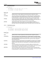
Format Enumeration
This IOCTL is used to enumerate the information of format (width, heght, bytesperline, image size, pixel
format etc.) those are supported by current decoder.
IOCTL: VIDIOC_ENUM_FMT
As per current decoder’s interface type (INTERFACE_TYPE_RAW, INTERFACE_TYPE_BT656,
INTERFACE_TYPE_BT1120), it will fill the structure.
It will take pointer to instance of v4l2_fmtdesc structure as an output parameter.
If data flow path 2 is used, it will enumerate pixel format that are available at the output of the Resizer.
Following are the pixel formats supported…
Table 1. Pixel Formats Supported by VIDIOC_ENUM_FMT (1)
SOC
Raw Bayer Data Input
Raw YCbCr (YUV) Input
DM6446
V4L2_PIX_FMT_SBGGR16 (Raw Mode – Bayer Pattern GrRBGb – 16 bit)
V4L2_PIX_FMT_SBGGR8 (Raw Mode – Bayer Pattern GrRBGb – 8 bit). This is
A-Law compressed.
V4L2_PIX_FMT_UYVY
V4L2_PIX_FMT_YUYV
DM355
V4L2_PIX_FMT_SBGGR16 (Raw Mode – Bayer Pattern GrRBGb – 16 bit)
V4L2_PIX_FMT_SBGGR8 (Raw Mode – Bayer Pattern GrRBGb – 8 bit). This is
A-Law compressed.
V4L2_PIX_FMT_UYVY
V4L2_PIX_FMT_UYVY
V4L2_PIX_FMT_YUYV
DM365
V4L2_PIX_FMT_SBGGR16 (Raw Mode – Bayer Pattern GrRBGb – 16 bit)
V4L2_PIX_FMT_SBGGR8 (Raw Mode – Bayer Pattern GrRBGb – 8 bit). This is
A-Law compressed or DPCM compressed based on compression algorithm
selected in CCDC configuration.
V4L2_PIX_FMT_UYVY
V4L2_PIX_FMT_NV12
V4L2_PIX_FMT_UYVY
V4L2_PIX_FMT_YUYV
V4L2_PIX_FMT_NV12
(1)
Pixel formats shown in italics require data flow path 2 to be configured in the driver.
Example:
struct v4l2_fmtdesc fmt;
i = 0;
while(1) {
fmt.index = i;
ret = ioctl(fd, VIDIOC_ENUM_FMT,& fmt);
if(ret) {
break;
}
printf("description = %s\n",fmt.description);
if(fmt.type == V4L2_BUF_TYPE_VIDEO_CAPTURE)
printf("Video capture type\n");
if(fmt.pixelformat == V4L2_PIX_FMT_UYVY)
printf("V4L2_PIX_FMT_UYVY\n");
i++;
}
SPRUGP6 – June 2009
Submit Documentation Feedback
LSP 2.10 Davinci Linux VPFE Capture Driver
19
Driver Overview
2.2.5.10
www.ti.com
Set Format
This IOCTL is used to set format for current decoder.
IOCTL: VIDIOC_S_FMT
Driver will validate the input parameters. Driver will return an error if parameters are not valid otherwise
driver will configure these parameters.
It will take pointer to instance of v4l2_format structure as an input parameter. Format type will be set as
V4L2_BUF_TYPE_VIDEO_CAPTURE for capture driver. v4l2_format structure contains parameters like
Pixel format, size of image, bytes per line, field type. Driver will adjust the width and height to match with
the hardware.
Note:
If the preview-Resizer is configured in the continuous mode, calling VIDIOC_S_FMT IOCTL
with a pixel format marked italic in Table 1 will use data flow path 2 (i.e data is output from
Resizer). In this mode, when capturing interlaced video, only second field is captured to
buffer and is scaled up by 2 to get the required height. So the resulting video is
de-interlaced. This mean real interlaced capture is not supported in continuous mode.
Examples:
For using MMAP:
struct v4l2_format fmt;
memset(&fmt, 0, sizeof(fmt));
fmt.type = V4L2_BUF_TYPE_VIDEO_CAPTURE;
fmt.fmt.pix.pixelformat = V4L2_PIX_FMT_UYVY;
fmt.fmt.pix.width = 720;
fmt.fmt.pix.height = 480;
fmt.fmt.pix.field = V4L2_FIELD_INTERLACED;
ret = ioctl(fd, VIDIOC_S_FMT, &fmt);
if(ret) {
perror("VIDIOC_S_FMT\n");
close(fd);
return -1;
}
Note:
When using the MMAP based buffer exchange, the application fills in the width, height, pixel
format and field. The driver calculates bytesperline and sizeimage, and returns the same to
the application.
For using USERPTR:
struct v4l2_format fmt;
memset(&fmt, 0, sizeof(fmt));
fmt.type = V4L2_BUF_TYPE_VIDEO_CAPTURE;
fmt.fmt.pix.pixelformat = V4L2_PIX_FMT_UYVY;
fmt.fmt.pix.bytesperline = 720*2; // adjust this to be multiple of 32
fmt.fmt.pix.sizeimage = fmt.fmt.pix.bytesperline * 480;
/* Driver calculates width and height based on the above */
fmt.fmt.pix.field = V4L2_FIELD_INTERLACED;
ret = ioctl(fd, VIDIOC_S_FMT, &fmt);
if(ret) {
perror("VIDIOC_S_FMT\n");
close(fd);
return -1;
}
Note:
20
When using the USERPTR based buffer exchange, the application fills in bytesperline,
sizeimage, pixel format and field. The driver calculates the width and height, and returns the
same to the application.
LSP 2.10 Davinci Linux VPFE Capture Driver
SPRUGP6 – June 2009
Submit Documentation Feedback
Driver Overview
www.ti.com
The driver makes adjusts the parameters as follows:
Table 2. Parameter Adjustments
Parameter
Description
height
Minimum height is 1 line for progressive scan and 2 lines for interlaced scan.
Maximum height is active lines of the standard selected (for data path 1) or height of QXGA
resolution (1536 lines for data flow path 2) .
width
Minimum width is 32/bpp (bytes per pixel).
Maximum width is maximum active pixels of the standard selected (for data flow path 1) or line
size of the IPIPE (1344 pixels for DM355 or 2176 for DM365).
bytesperline
Multiple of 32
2.2.5.11
Get Format
This IOCTL is used to get format for current decoder.
IOCTL: VIDIOC_G_FMT
Driver will provide format parameters in the structure pointer passed as an argument.
It will take pointer to instance of v4l2_format structure as an input parameter. Format type will be set as
V4L2_BUF_TYPE_VIDEO_CAPTURE for capture driver. v4l2_format structure contains parameters like
Pixel format, size of image, bytes per line, field type.
Example:
struct v4l2_format fmt;
fmt.type = V4L2_BUF_TYPE_VIDEO_CAPTURE;
ret = IOCTL(fd, VIDIOC_G_FMT, &fmt);
if(ret) {
perror("VIDIOC_G_FMT\n");
close(fd);
return -1;
}
2.2.5.12
Try Format
This IOCTL is used to validate the format for current decoder.
IOCTL: VIDIOC_TRY_FMT
Driver will adjust the parameter as required by the hardware.
It will take pointer to instance of v4l2_format structure as an input parameter.
Format type will be set as V4L2_BUF_TYPE_VIDEO_CAPTURE for capture driver. v4l2_format structure
contains parameters like Pixel format, size of image, bytes per line, field type.
Example:
struct v4l2_format fmt;
fmt.type = V4L2_BUF_TYPE_VIDEO_CAPTURE;
fmt.fmt.pix.pixelformat = V4L2_PIX_FMT_UYVY;
fmt.fmt.pix.width = 720;
fmt.fmt.pix.height = 480;
fmt.fmt.pix.field = V4L2_FIELD_INTERLACED;
ret = IOCTL(fd, VIDIOC_TRY_FMT, &fmt);
if(ret) {
perror("VIDIOC_TRY_FMT \n");
close(fd);
return -1;
}
Parameters are adjusted by driver as given in Table 2.
SPRUGP6 – June 2009
Submit Documentation Feedback
LSP 2.10 Davinci Linux VPFE Capture Driver
21
Driver Overview
2.2.5.13
www.ti.com
Set Stream Parameters
This IOCTL is used to change the fps from 60 to 30 for 720P@60fps capture from TVP7002. This is only
added as a work around to support 720P@30fps.
IOCTL: VIDIOC_S_PARM
Example:
struct v4l2_streamparm param;
param.type = V4L2_BUF_TYPE_VIDEO_CAPTURE;
param.parm.capture.timeperframe.numerator = 1;
param.parm.capture.timeperframe.denominator = 30;
ret = IOCTL(fd, VIDIOC_S_PARM,¶m);
if(ret) {
perror("VIDIOC_S_PARM \n");
close(fd);
return -1;
}
2.2.5.14
Get Stream Parameters
This IOCTL is used to get the current stream params when doing capture from TVP7002. This is only
added as a work around to support 720P@30fps.
IOCTL: VIDIOC_G_PARM
Example:
struct v4l2_streamparm param;
param.type = V4L2_BUF_TYPE_VIDEO_CAPTURE;
param.parm.capture.timeperframe.numerator = 1;
param.parm.capture.timeperframe.denominator = 30;
ret = IOCTL(fd, VIDIOC_G_PARM,¶m);
if(ret) {
perror("VIDIOC_G_PARM \n");
close(fd);
return -1;
}
printf("parm.numerator = %d\n",
param.parm.capture.timeperframe.numerator);
printf("parm.denominator = %d\n",
param.parm.capture.timeperframe.denominator);
2.2.5.15
Query Control
This IOCTL is used to get the information of control commands supported by current decoder.
IOCTL: VIDIOC_QUERYCTRL
Driver will fill Id member in this structure, with the control id defined in V4L2 header file, for which
information is needed.
If the control command specified by Id is not supported in current decoder, driver will return an error.
It will take pointer to instance of v4l2_queryctrl structure as an output parameter.
Example:
struct v4l2_queryctrl ctrl;
ctrl.id = V4L2_CID_GAIN;
ret = IOCTL(fd, VIDIOC_QUERYCTRL,&ctrl);
if(ret) {
perror("VIDIOC_QUERYCTRL \n");
close(fd);
return -1;
}
printf("name = %s\n",ctrl.name);
printf("min = %d max = %d step = %d default = %d\n",
ctrl.minimum, ctrl.maximum, ctrl.step, ctrl.default_value);
22
LSP 2.10 Davinci Linux VPFE Capture Driver
SPRUGP6 – June 2009
Submit Documentation Feedback
Driver Overview
www.ti.com
2.2.5.16
Set Control
This IOCTL is used to set the value for particular control in current decoder.
IOCTL: VIDIOC_S_CTRL
If the control command specified by Id is not supported in current decoder, driver will return an error. It will
take pointer to instance of v4l2_control structure as an input parameter.
Example:
struct v4l2_control ctrl;
ctrl.id = V4L2_CID_GAIN;
ctrl.value = 5;
ret = IOCTL(fd, VIDIOC_S_CTRL, &ctrl);
if(ret) {
perror("VIDIOC_S_CTRL\n");
close(fd);
return -1;
}
2.2.5.17
Get Control
This IOCTL is used to get the value for particular control in current decoder.
IOCTL: VIDIOC_G_CTRL
If the control command specified by Id is not supported in current decoder, driver will return an error. It will
take pointer to instance of v4l2_control structure as an output parameter.
Example:
v4l2_std_id ctrl;
ret = IOCTL(fd, VIDIOC_G_CTRL, &ctrl);
if(ret) {
perror("VIDIOC_G_CTRL \n");
close(fd);
return -1;
}
2.2.5.18
Queue Buffer
This IOCTL is used to enqueue the buffer in buffer queue.
IOCTL: VIDIOC_QBUF
Application has to specify buffer type (V4L2_BUF_TYPE_VIDEO_CAPTURE), buffer index and memory
type (V4L2_MEMORY_MMAP or V4L2_MEMORY_USERPTR) at the time of queuing.
If this IOCTL is called with the file descriptor, with which VIDIOC_REQBUFS is not been done, driver will
return an error.
Driver will enqueue buffer, if buffer queue is not empty. If queue is empty then driver will directly write
buffer address to hardware registers.
It will take pointer to instance of v4l2_ buffer structure as an input parameter.
When data flow path 2 is used, there are two output images available in the buffer. First output image size
is calculated based on width, height and pixel format set through S_FMT. Second output image from
RSZ-B is available at the end of first output image. So its offset is sizeimage reported by driver in S_FMT
adjusted to 32-byte boundary as follows:
• Offset of second output image in the de-queued buffer is calculated as
round32(width*height*bpp). For VGA with UYVY pixel format used for first output, this is
round32(640*480*2). That is, Offset is 614400.
• Offset of C-plane in the buffer for pixel format NV12 is calculated as round32(width*height). For
VGA, with UYVY pixel format, this is round32(640*480). That is, Offset is 307200 bytes.
SPRUGP6 – June 2009
Submit Documentation Feedback
LSP 2.10 Davinci Linux VPFE Capture Driver
23
Driver Overview
www.ti.com
Examples:
struct v4l2_buffer buf;
buf.type = V4L2_BUF_TYPE_VIDEO_CAPTURE;
buf.memory = V4L2_MEMORY_MMAP;
buf.index = 0;
ret = IOCTL(fd, VIDIOC_QBUF, &buf);
if(ret) {
perror("VIDIOC_QBUF\n");
close(fd);
return -1;
}
Or
struct v4l2_buffer buf;
buf.type = V4L2_BUF_TYPE_VIDEO_CAPTURE;
buf.memory = V4L2_MEMORY_USERPTR;
buf.index = 0;
/* length of the buffer. Calculated based on CCDC/RSZ-A output
* image size that is reported by driver in S_FMT sizeimage. Second
* output(RSZ-B output)image size is equal to
* width * height * bpp. these parameters
* are set in Resizer device for output2. bpp depends on pixel format
* set in output2 structure.
*/
buf.length = first output image size + (second output image size)
ret = ioctl(fd, VIDIOC_QBUF, &buf);
if(ret) {
perror("VIDIOC_QBUF\n");
close(fd);
return -1;
}
2.2.5.19
Dequeue Buffer
This IOCTL is used to dequeue the buffer in buffer queue.
IOCTL: VIDIOC_DQBUF
Application has to specify buffer type (V4L2_BUF_TYPE_VIDEO_CAPTURE) and memory type
(V4L2_MEMORY_MMAP or V4L2_MEMORY_USERPTR) at the time of dequeueing.
If this IOCTL is called with the file descriptor, with which VIDIOC_REQBUFS is not been done, driver will
return an error.
Driver will enqueue buffer, if buffer queue is not empty.
If channel is opened in non blocking mode, this IOCTL call will return immediately if there is no buffer in
queue.
It will take pointer to instance of v4l2_ buffer structure as an output parameter.
Example:
struct v4l2_buffer buf;
buf.type = V4L2_BUF_TYPE_VIDEO_CAPTURE;
buf.type = V4L2_MEMORY_MMAP;
ret = IOCTL(fd, VIDIOC_DQBUF, &buf);
if(ret) {
perror("VIDIOC_DQBUF\n");
close(fd);
return -1;
}
24
LSP 2.10 Davinci Linux VPFE Capture Driver
SPRUGP6 – June 2009
Submit Documentation Feedback
Driver Overview
www.ti.com
2.2.5.20
Stream On
This IOCTL is used to start video capture functionality.
IOCTL: VIDIOC_STREAMON
If this IOCTL is called with the file descriptor, with which VIDIOC_REQBUFS is not been done, driver will
return an error.
If streaming is already started, this IOCTL call will return an error.
Example:
ret = IOCTL(fd, VIDIOC_STREAMON, NULL);
if(ret) {
perror("VIDIOC_STREAMON \n");
close(fd);
return -1;
}
2.2.5.21
Stream Off
This IOCTL is used to stop video capture functionality.
IOCTL: VIDIOC_STREAMOFF
If this IOCTL is called with the file descriptor, with which VIDIOC_REQBUFS is not been done, driver will
return an error.
If streaming is yet not started, this IOCTL call will return an error.
Example:
ret = IOCTL(fd, VIDIOC_STREAMOFF, NULL);
if(ret) {
perror("VIDIOC_STREAMOFF \n");
close(fd);
return -1;
}
2.2.5.22
Set Priority
This IOCTL is used to set priority for file descriptor.
IOCTL: VIDIOC_S_PRIORITY
It will take pointer to instance of v4l2_priority structure as an intput parameter.
Example:
enum v4l2_priority priority = V4L2_PRIORITY_DEFAULT;
ret = IOCTL(fd, VIDIOC_S_PRIORITY, &priority);
if(ret) {
perror("VIDIOC_S_PRIORITY\n");
close(fd);
return -1;
}
SPRUGP6 – June 2009
Submit Documentation Feedback
LSP 2.10 Davinci Linux VPFE Capture Driver
25
Driver Overview
2.2.5.23
www.ti.com
Get Priority
This IOCTL is used to get priority for file descriptor.
IOCTL: VIDIOC_G_PRIORITY
It will take pointer to instance of v4l2_priority structure as an output parameter.
Example:
enum v4l2_priority priority;
ret = IOCTL(fd, VIDIOC_G_PRIORITY, &priority);
if(ret) {
perror("VIDIOC_G_PRIORITY\n");
close(fd);
return -1;
}
If(priority == V4L2_PRIORITY_DEFAULT)
Printf("Default Priority\n");
2.2.5.24
Get Decoder Parameters
This IOCTL is used to get parameters of current decoder which are specific to respective decoder and can
not be got with v4l2 ioctls.
IOCTL: VPFE_CMD_G_DECODER_PARAMS
It takes void* as an output argument which ultimately points to the structure to the decoder set_params
structure instance.
Example:
/* consider that TVP7002 is the current decoder */
tvp7002_params params;
ret = IOCTL(fd, VPFE_CMD_G_DECODER_PARAMS, ¶ms);
if(ret) {
perror("VPFE_CMD_G_DECODER_PARAMS \n");
close(fd);
return -1;
}
2.2.5.25
Set Decoder Parameters
This IOCTL is used to set parameters of current decoder which are specific to respective decoder and can
not be set with v4l2 ioctls.
IOCTL: VPIF_CMD_S_DECODER_PARAMS
It takes void* as an output argument which ultimately points to the structure to the decoder set_params
structure instance.
Example:
/* consider that TVP7002 is the current decoder */
tvp7002_params params;
ret = IOCTL(fd, VPFE_CMD_S_DECODER_PARAMS, ¶ms);
if(ret) {
perror("VPFE_CMD_G_DECODER_PARAMS \n");
close(fd);
return -1;
}
26
LSP 2.10 Davinci Linux VPFE Capture Driver
SPRUGP6 – June 2009
Submit Documentation Feedback
Driver Overview
www.ti.com
2.2.5.26
Set CCDC Parameters
This IOCTL is used to set CCDC parameters.
IOCTL: VPFE_S_CCDC_PARAMS
It takes void* as an input argument which ultimately points to the ccdc_param structure instance.
Example:
struct ccdc_param params; // initialize the CCDC parameters.
ret = IOCTL(fd, VPFE_S_CCDC_PARAMS, ¶ms);
if(ret) {
perror("VPFE_S_CCDC_PARAMS\n");
close(fd);
return -1;
}
2.2.5.27
Get CCDC Parameters
This IOCTL is used to get CCDC parameters.
IOCTL: VPFE_G_CCDC_PARAMS
It takes void* as an output argument which ultimately points to the ccdc_param structure instance.
Example:
struct ccdc_param params;
ret = IOCTL(fd, VPFE_G_CCDC_PARAMS, ¶ms);
if(ret) {
perror("VPFE_G_CCDC_PARAMS\n");
close(fd);
return -1;
}
2.2.5.28
Configure TVP 5146 Parameters
Replaced with Get/Set decoder parameters as shown in Section 2.2.5.24 and Section 2.2.5.25.
2.2.5.29
Set MT9T001 Parameters
This IOCTL is for backward compatibility. This calls setparam() call from MT9T001/MT9T031 driver if it is
the current decoder.
IOCTL: VPFE_CMD_S_MT9T001_PARAMS
Example:
/* consider that MT9T001.MT9T031 is the current decoder */
mt9t001_params params; // initialize the mt9t001 parameters.
ret = IOCTL(fd, VPFE_CMD_S_MT9T001_PARAMS, ¶ms);
if(ret) {
perror("VPFE_CMD_S_MT9T001_PARAMS\n");
close(fd);
return -1;
}
SPRUGP6 – June 2009
Submit Documentation Feedback
LSP 2.10 Davinci Linux VPFE Capture Driver
27
Driver Overview
2.2.5.30
www.ti.com
Get MT9T001 Parameters
This IOCTL is for backward compatibility. Driver provides functionality to fetch parameters of
MT9T001/MT9T031, if it is a current decoder.
IOCTL: VPFE_CMD_G_MT9T001_PARAMS
It takes void* as an output argument which ultimately points to the structure to the mt9t001_params
structure instance.
Example:
/* consider that MT9T001 is the current decoder */
mt9t001_params params;
ret = IOCTL(fd, VPFE_CMD_G_MT9T001_PARAMS, ¶ms);
if(ret) {
perror("VPFE_CMD_G_MT9T001_PARAMS\n");
close(fd);
return -1;
}
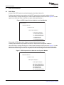
2.2.6
ISR Handling
CCDC has three interrupt registers :- VINT0, VINT1 and VINT2. They can be programmed to occur at any
instance relative to VD signal from the hardware. In the VPFE driver, interrupts are used to mark a frame
capture is complete and schedule next frame for capture and also release the frame to application.
Different interrupts are used for this purpose based on whether the capture happens from output of CCDC
or output of Resizer.
2.2.6.1
Output From CCDC (Data Flow Path 1)
For this, VINT0 is configured to occur at VD. This will generate the frame and field interrupts to align with
the frame and field start. VINT1 is configured to occur at midway in the frame.
For interlaced scan, frame interrupt coincides with the top field (first field) interrupt and bottom field
(second field) interrupt happens at the middle of frame interrupts. For progressive scan, only frame
interrupts happens. VINT1 is configured to happens at midway between frame interrupts for progressive
scans.
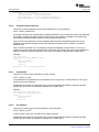
Figure 5 illustrates the relationship between the first interrupt and incoming data in case of frame interrupt.
Figure 5. Interrupt Handling Timing Diagram
CPU Kicks the VPFE Module
frame[n]
top field[n]
1st Frame
Insterrupt
(output start)
bottom field[n]
Bottom
Field
Interrupt
frame[n+1]
top field[n+1]
bottom field[n+1]
2nd
Frame
Interrupt
Bottom
Field
Interrupt
capture frame[n+2]
top field[n+2]
bottom field[n+2]
3rd
Frame
Interrupt
Bottom
Field
Interrupt
time
4th
Frame
Interrupt
This is the sequence:
1. VPFE Capture driver attaches, vpfe_isr() routine to process VINT0 and vdint1_isr() to process VINT1
interrupts.
2. When application call STREAMON IOCTL, vpfe driver calls configure() function from the ccdc hw
interface to configure CCDC. As part of this, CCDC module configures VINT0 and VINT1 (if
progressive scan).
3. The address of the first frame is configured in CCDC when application calls VIDIOC_STREAMON
IOCTL.
4. As shown in the above figure, the first interrupt comes, when CCDC starts storing frame in the
SDRAM.
28
LSP 2.10 Davinci Linux VPFE Capture Driver
SPRUGP6 – June 2009
Submit Documentation Feedback
Driver Overview
www.ti.com
5. Driver will configure address for the next frame in CCDC registers when interrupt for the first (bottom)
field is received. For the even field interrupt, it just marks that capture is completed for the current
frame.
6. After single frame capture interrupt, driver will get system time using jiffies timer. This time will be
capture time for particular frame. Application can get this empty buffer with capture time by calling
IOCtl with VIDIOC_DQBUF command.
7. If there is only single buffer in the incoming queue of the driver, driver will not update CCDC registers
and CCDC will capture same frame until application calls VIDIOC_QBUF IOCtl. In the VIDIOC_QBUF
IOCtl, driver will set the address of buffer to be queued in the CCDC registers if the buffer queue is
empty and if the CCDC device is currently capturing the bottom field. Otherwise the buffer is queued.
So when the next interrupt comes, buffer is already available to the device for capture. There is a
restriction here. If application does not call VIDIOC_QBUF IOCtl after the buffer queue becomes empty
and before the next interrupt, same frame will get captured i.e. frame drop will occur.
2.2.6.2
Output From Resizer (Data Flow Path 2)
Interrupt handling is concerned, this is similar to the case when data is output from CCDC. Driver needs to
decide when to mark a frame buffer has completed capture and when to schedule next frame for capture.
RSZ_INT_DMA (for DM365) or (IPIPE_INT1_SDR) interrupt happens when the Resizer output image is
written to SDRAM. So this interrupt handling is used to free up current frame buffer and schedule next
frame buffer for capture. The buffer address is written to Resizer register as part of this interrupt handling.
The assumption is that this interrupt will occur before next frame data arrive at the Resizer.
vpfe_imp_dma_isr() is attached to handle this interrupt.
The current frame is marked as complete at VINT2 which is configured to occur at the end of the frame
(height-1). vpfe_isr() is attached to INT2 interrupt handling/
SPRUGP6 – June 2009
Submit Documentation Feedback
LSP 2.10 Davinci Linux VPFE Capture Driver
29
Portability
www.ti.com
3
Portability
3.1
Decoders
3.1.1
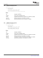
Data Structures and API for Decoder Interface
3.1.1.1
Decode Device Structure
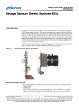
/* decoder device structure */
struct decoder_device {
u8 name[DECODER_MAX_NAME];
vid_capture_interface_type if_type;
int channel_id;
u32 capabilities;
int (*initialize) (void *dec);
struct standard_ops *std_ops;
struct control_ops *ctrl_ops;
struct input_ops *input_ops;
struct format_ops *fmt_ops;
struct param_ops *params_ops;
int (*deinitialize)(void *dec);
int (*read_vbi_data)(struct v4l2_sliced_vbi_data, void *dec);
int (*get_sliced_vbi_cap(struct v4l2_sliced_vbi_cap *cap,
void *dec);
};
decoder_device
name
Name of decoder. For example, MT9T001
if_type
ORing of different interface types supported by this decoder. For example,
INTERFACE_TYPE_BT656, INTERFACE_TYPE_BT1120, INTERFACE_TYPE_RAW,
INTERFACE_TYPE_YCBCR_SYNC_8, INTERFACE_TYPE_YCBCR_SYNC_16,
INTERFACE_TYPE_YCBCR_SYNC_10BIT.
channel_id
It indicates for which channel id, this decoder instance is used.
capabilities
It indicates VBI is supported or not.
Function Pointers
•
•
•
•
•
initialize() function
Any new decoder needs to define certain functions, and store these function pointers
in decoder_device structure.
VPFE keeps instance of decoder_device structure for each registered decoders.
VPFE will call these functions, as per requirement.
While calling, VPFE will pass pointer to respective decoder_device structure object.
VPFE gets this object at the time of decoder registration. Decoder will register itself
to VPFE module at the time of module insertion.
This function will be called whenever decoder needs to be initialized.
Its prototype is: int initialize(void *dec);
deinitialize() function
This function will be called whenever decoder needs to be deinitialized.
Its prototype is: int deinitialize(void *dec);
30
LSP 2.10 Davinci Linux VPFE Capture Driver
SPRUGP6 – June 2009
Submit Documentation Feedback
Portability
www.ti.com
3.1.1.2
Standard Ops Structure
/* standard ops structure */
struct standard_ops {
int count;
int (*enumstd) (struct v4l2_standard * argp, void *dec);
int (*querystd) (v4l2_std_id *argp, void *dec);
int (*setstd)
(v4l2_std_id *argp, void *dec);
int (*getstd)
(v4l2_std_id *argp, void *dec);
};
standard_ops
count
Indicates number of standard supported for particular decoder on particular channel.
enumstd()
This is the function for standard enumeration. (Described in Design section.)
querystd()
This is the function for standard detection. (Described in Design section.)
setstd()
This is the function for setting the standard. (Described in Design section.)
getstd()
This is the function for setting the standard. (Described in Design section.)
3.1.1.3
Control Ops Structure
/* control ops structure */
struct control_ops {
int count;
int (*queryctrl) (struct v4l2_queryctrl *argp, void *dec);
int (*setcontrol) (struct v4l2_control *argp, void *dec);
int (*getcontrol) (struct v4l2_control *argp, void *dec);
};
control_ops
count
Indicates number of control supported for particular decoder on particular channel.
queryctrl()
This is the function for query control. (Described in Design section.) dec contains the
pointer to decoder_device structure which points to the decoder instance of current
channel. It takes v4l2_querycontrol instance as an output argument. It will validate
passed control id, if it is valid one, it will filled information regarding that control into
structure.
setcontrol()
This is the function for setting the particular control value. dec contains the pointer to
decoder_device structure which points to the decoder instance of current channel. It
takes v4l2_control instance as an input argument. It will validate passed control id and
value, and if it is valid combination, will set the value in decoder.
getcontrol()
This is the function for getting the value for particular control. dec contains the pointer to
decoder_device structure which points to the decoder instance of current channel. It
takes v4l2_control instance as an output argument. It will validate passed control id, if it
is valid, it will fill value for that control id in structure.
SPRUGP6 – June 2009
Submit Documentation Feedback
LSP 2.10 Davinci Linux VPFE Capture Driver
31
Portability
3.1.1.4
www.ti.com
Input Ops Structure
/* input ops structure
struct input_ops {
int count;
int (*enuminput)
int (*setinput)
int (*getinput)
};
*/
(struct v4l2_input * argp, void *dec);
(int *argp, void *dec);
(int *argp, void *dec);
input_ops
count
Indicates number of input supported for particular decoder on particular channel.
enuminput()
This is the function for input enumeration. dec contains the pointer to decoder_device
structure which points to the decoder instance of current channel. It takes v4l2_input as
an output argument. It contains index field, as per value of it, structure will be filled.
setinput()
This is the function for setting the input. dec contains the pointer to decoder_device
structure which points to the decoder instance of current channel. It takes input index as
an input argument and as per value of it; input will be set in decoder.
getinput()
This function will detect, input is present or not. dec contains the pointer to
decoder_device structure which points to the decoder instance of current channel. It
takes input index as an output argument and it will be filled with the current input value.
3.1.1.5
Format Ops Structure
/* format ops structure
struct format_ops {
int count;
int (*enumformat)
int (*tryformat)
int (*setformat)
int (*getformat)
};
*/
(struct
(struct
(struct
(struct
v4l2_fmtdesc *argp, void *dec);
v4l2_format *argp, void *dec);
v4l2_format *argp, void *dec);
v4l2_format *argp, void *dec);
format_ops
count
Indicates number of format supported for particular decoder on particular channel.
enumformat()
This is the function for format enumeration. dec contains the pointer to decoder_device
structure which points to the decoder instance of current channel. It takes v4l2_fmtdesc
as an output argument and index is one of the fields of it. As per value of index, structure
will be filled. Structure contains information like buffer type for the format, description
string, and pixel format.
tryformat()
This is the function for trying the format, to check whether it is valid or not. dec contains
the pointer to decoder_device structure which points to the decoder instance of current
channel. It takes v4l2_format as an input argument. It will validate the passed value in
structure.
setformat()
This is the function to set new format. dec contains the pointer to decoder_device
structure which points to the decoder instance of current channel. It takes v4l2_format as
an input argument. It will validate it and then set it as a current format.
getformat()
This is the function to get current format. dec contains the pointer to decoder_device
structure which points to the decoder instance of current channel. It takes v4l2_format as
an output argument. It will be filled with the current format values.
32
LSP 2.10 Davinci Linux VPFE Capture Driver
SPRUGP6 – June 2009
Submit Documentation Feedback
Portability
www.ti.com
3.1.1.6
Parameter Ops Structure
/* Parameters ops structure */
struct param_ops {
int (*setparams) (void *params, void *dec);
int (*getparams) (void *params, void *dec);
};
param_ops
setparams()
It is to set device parameters. dec contains the pointer to decoder_device structure
which points to the decoder instance of current channel.
getparams()
It is to get device parameters. dec contains the pointer to decoder_device structure
which points to the decoder instance of current channel.
3.1.1.7
vpif_register_decoder Function
int vpif_register_decoder(struct decoder_device *decoder);
Decoder will call this function from module_entry function, at the time of module insertion. It will register
itself to VPFE module.
3.1.1.8
vpif_unregister_decoder Function
int vpif_unregister_decoder(struct decoder_device *decoder);
Decoder will call this function from module_exit function, at the time of module insertion. It will unregister
itself to VPFE module.
3.1.2
Supported Decoders
The following decoders are supported in this release:
• TVP5146 (driver module tvp514x.[ch])
• TVP7002 (driver module tvp7002.[ch]). Tested only on DM365.
• MT9T001/MT9T031 (driver module mt9t001.[ch])
• MT9P031 (driver module mt9p031.[ch])
All these drivers are developed using the decoder interface described earlier. The decoder specific
commands (like std, input, param etc) are passed directly by VPFE capture driver to the currently active
decoder.
SPRUGP6 – June 2009
Submit Documentation Feedback
LSP 2.10 Davinci Linux VPFE Capture Driver
33
Portability
3.1.3
www.ti.com
Adding New Decoder Support
VPFE capture driver is made such that if new decoder needs to be supported, it can be done by
implementing some standard functions. One common vid_decoder_if.h file is available describing the
interface for new decoder. To develop a new decoder driver, use existing drivers (that is close enough to
the driver being written) as template. To support a new decoder following additional changes required in
addition to developing a decoder module.
• In ccdc_common.c timing information for different standards are defined. Each timing information is
tagged by a name. So when adding new standards to the decoder, make sure to use an existing tag or
if new, add it to this file as well. Update also #define CCDC_CH0_MAX_MODES.
• Make sure to use appropriate interface type. If existing interface types are re-used, then it might work
with out any change. VPFE Capture driver reads the interface type from the decoder and pass it to
CCDC for configuration. Current driver has tested BT.656, BT.1120 and Raw capture interfaces. If a
different interface is to be configured, check the ccdc_xxx.c (xxx refers to SoC, example ccdc_dm355.c
for DM355) module, configure() function to verify if the required settings in CCDC is done for the
interface being used.
• Currently davinci_vpfe.h defines Maximum number of decoders supported as 5. (#define
VPFE_CAPTURE_NUM_DECODERS 5). For a specific system, if one or more decoder is not used,
the same can be compiled out using configuration variable available for the decoder. Remember to
change the above constant if number of decoders in the system crosses 5.
• Define decoder type constant in davinci_vpfe.h and add it to vpfe_open() and vpfe_init() functions in
davinci_vpfe.c
34
LSP 2.10 Davinci Linux VPFE Capture Driver
SPRUGP6 – June 2009
Submit Documentation Feedback
User Interface
www.ti.com
4
User Interface
4.1
API
VPFE capture driver is a V4L2 device. Please refer V4L2 specification for the details of IOCTL calls.
Please refer the design section for the IOCTL calls supported.
4.2
4.2.1
Data Structures
CCDC Configuration
VPFE Capture driver provides VPFE_CMD_S_CCDC_PARAMS to set CCDC configuration and
VPFE_CMD_G_CCDC_PARAMS to get CCDC configuration. Driver calls setparams() at the ccdc hw
interface to pass the parameters to CCDC module and calls getparams() to get the parameters. Old
IOCTLS, VPFE_CMD_CONFIG_CCDC_RAW & VPFE_CMD_CONFIG_CCDC_YCBCR are supported for
backward compatibility.
Application includes ccdc_xxx.h (example ccdc_davinci.c for DM6446, ccdc_dm355.c for DM355 and so
on) if it needs to configure CCDC. Usually this is required only for Raw bayer capture to enable and
configure CCDC modules such as Defect Pixel Correction, A-Law compression, Color Space Conversion
etc. For YCbCr capture standard v4l2 Ioctls suffice.
Following high level data structures are used by application to configure CCDC:struct ccdc_config_params_raw {
/* fields of this structure varies from SoC to SoC.
* check the respective ccdc header file for details.
*/
};
Following structure used for YCbCr capture.
struct ccdc_params_ycbcr {
/* fields of this structure varies from SoC to SoC.
* check the respective ccdc header file for details.
*/
};
Support for following CCDC pre-processing modules are available on DM365. These modules can be
configured through the above IOCTL call.
• Defect Pixel Correction
• Color Space Conversion
• Linearization
• Culling
• A-Law and DPCM compression
• Black Clamp
4.2.2
CCDC Control
Following control IDs (defined in davinci_vpfe.h) are available for CCDC control Ioctls:
• VPFE_CCDC_CID_R_GAIN – Adjustment of Gain for R
• VPFE_CCDC_CID_GR_GAIN – Adjustment of Gain for Gr
• VPFE_CCDC_CID_GB_GAIN – Adjustment of Gain for Gb
• VPFE_CCDC_CID_B_GAIN – Adjustment of Gain for B
• VPFE_CCDC_CID_OFFSET – Offset adjustment
SPRUGP6 – June 2009
Submit Documentation Feedback
LSP 2.10 Davinci Linux VPFE Capture Driver
35
User Interface
4.2.3
www.ti.com
MT9T001 Parameter Structure
include file is mt9t001.h
struct mt9t001_params {
v4l2_std_id std;
int inputidx;
struct mt9t001_format_params format;
struct mt9t001_rgb_gain rgb_gain;
struct mt9t001_black_level_calibration black_calib;
};
Fields
4.2.4
std
Standard of MT9T001
inputidx
Index of input of MT9T001 device
format
Standard specific MT9T001 parameters. See mt9001.h for details.
rgb_gain
RGB gain parameters. See mt9001.h for details.
black_calib
Black level calibration value. See mt9001.h for details.
MT9P031 Parameter Structure
include file is mt9p031.h
struct mt9p031_params {
v4l2_std_id std;
int inputidx;
struct mt9p031_format_params format;
struct mt9p031_rgb_gain rgb_gain;
struct mt9p031_test_pat test_pat;
struct mt9p031_misc_cfg misc_cfg;
};
Fields
36
std
Standard of MT9P031
inputidx
Index of input of MT9P031 device
format
Standard specific MT9T001 parameters. See mt9p031.h for details.
rgb_gain
RGB gain parameters. See mt9p031.h for details.
test_pat
Test pattern to replace real image data. See mt9p031.h for details.
misc_cfg
Miscellaneous parameters. See mt9p031.h for details.
LSP 2.10 Davinci Linux VPFE Capture Driver
SPRUGP6 – June 2009
Submit Documentation Feedback
User Interface
www.ti.com
4.2.5
TVP5146 Parameter Structure
include file is tvp514x.h
struct tvp514x_params {
v4l2_std_id std;
int inputidx;
struct v4l2_format fmt;
};
Fields
4.2.6
std
Standard of TVP5146
inputidx
Index of input of TVP5146 device
fmt
VBI format (not supported in VPFE Capture driver)
TVP7002 Parameter Structure
include file is tvp7002.h
struct tvp7002_params {
v4l2_std_id std;
int inputidx;
struct alc_filter alc;
struct tvp7002_gain gain;
struct tvp7002_offset offset;
struct tvp7002_format_params format;
};
Fields
4.2.7
std
Standard of TVP7002
inputidx
Index of input of TVP7002 device
alc
ALC filter params. See tvp7002.h for details.
gain
Structure for gain information. See tvp7002.h for details.
offset
Structure for offset(brightness) information. See tvp7002.h for details.
format
Structure for tvp7002 format params.
Request Buffer Structure for V4L2
struct v4l2_requestbuffers
{
__u32
enum v4l2_buf_type
enum v4l2_memory
__u32
};
count;
type;
memory;
reserved[2];
Fields
count
Number of buffers requested
type
V4L2_BUF_TYPE_VIDEO_CAPTURE
memory
V4L2_MEMORY_MMAP or V4L2_MEMORY_USERPTR
SPRUGP6 – June 2009
Submit Documentation Feedback
LSP 2.10 Davinci Linux VPFE Capture Driver
37
User Interface
4.2.8
www.ti.com
Buffer Structure for V4L2
struct v4l2_buffer
{
__u32
enum v4l2_buf_type
__u32
__u32
enum v4l2_field
struct timeval
struct v4l2_timecode
__u32
/* memory location */
enum v4l2_memory
union {
__u32
unsigned long
} m;
__u32
__u32
__u32
index;
type;
bytesused;
flags;
field;
timestamp;
timecode;
sequence;
memory;
offset;
userptr;
length;
input;
reserved;
};
Relevant Fields for VPFE Capture Driver
38
index
Index of the buffer
type
Type of the data stream: V4L2_BUF_TYPE_VIDEO_CAPTURE
memory
V4L2_MEMORY_MMAP or V4L2_MEMORY_USERPTR
bytesused
The number of bytes occupied by the data in the buffer.
field
The field order of the image in the buffer
m.userptr
When memory is V4L2_MEMORY_USERPTR this is a pointer to the buffer in
virtual memory, set by the application.
m.offset
When memory is V4L2_MEMORY_MMAP this is the offset of the buffer from
the start of the device memory.
length
Size of the buffer
LSP 2.10 Davinci Linux VPFE Capture Driver
SPRUGP6 – June 2009
Submit Documentation Feedback
User Interface
www.ti.com
4.2.9
Query Capability Structure for V4L2
struct v4l2_capability
{
__u8
driver[16];
__u8
card[32];
__u8
bus_info[32];
__u32
version;
__u32
capabilities;
__u32
reserved[4];
};
Relevant Fields for VPFE Capture Driver
4.2.10
driver
ccdc capture
card
DaVinci EVM
bus_info
Platform
version
Version code for VPFE capture module
capabilities
V4L2_CAP_VIDEO_CAPTURE or V4L2_CAP_STREAMING
Input Structure for V4L2
struct v4l2_input
{
__u32
__u8
__u32
__u32
__u32
v4l2_std_id
__u32
__u32
};
index;
name[32];
type;
audioset;
tuner;
std;
status;
reserved[4];
Relevant Fields for VPFE Capture Driver
index
Index with value zero indicates first input type of first decoder that has been
registered at the time of module insertion, and after possible inputs for first
decoder, next index from application will be mapped to first input of second
decoder, and so on.
For example, if first registered decoder is TVP5146 and second is MT9T001,
and both are supporting one type of input; then if application will pass 0 as an
input index, it will enumerate input of TVP5146 and for input index 1, it will
enumerate input of MT9T001.
name
Name of video input
std
Every video input supports one or more different video standards. This field is
a set of all supported standards.
SPRUGP6 – June 2009
Submit Documentation Feedback
LSP 2.10 Davinci Linux VPFE Capture Driver
39
User Interface
4.2.11
www.ti.com
Standard Structure for V4L2
struct v4l2_standard
{
__u32
index;
v4l2_std_id
id;
__u8
name[24];
struct v4l2_fract frameperiod; /* Frames, not fields */
__u32
framelines;
__u32
reserved[4];
};
typedef __u64 v4l2_std_id;
struct v4l2_fract {
__u32
numerator;
__u32
denominator;
};
Relevant Fields for VPFE Capture Driver
index
Index of the supported standards
id
Standard id. Supported standards are mentioned in enumerations and define
section.
name
Name of the standard
frameperiod.numerator
Numerator value to set particular frame rate for standard.
frameperiod.denominator Denominator value to set particular frame rate for standard.
framelines
4.2.12
Total lines per frame including blanking.
Format Description Structure for V4L2
struct v4l2_fmtdesc
{
__u32
enum v4l2_buf_type
__u32
__u8
__u32
__u32
};
index;
type;
flags;
description[32];
pixelformat;
reserved[4];
/* Format number
/* buffer type
*/
*/
/* Description string */
/* Format fourcc
*/
Relevant Fields for VPFE Capture Driver
40
index
Index of the supported formats
type
Type of the data stream: V4L2_BUF_TYPE_VIDEO_CAPTURE.
description
Description of the format, a NUL-terminated ASCII string. This information is
intended for the user.
pixelformat
The image format identifier.
LSP 2.10 Davinci Linux VPFE Capture Driver
SPRUGP6 – June 2009
Submit Documentation Feedback
User Interface
www.ti.com
4.2.13
Format Structure for V4L2
struct v4l2_format
{
enum v4l2_buf_type type;
union
{
struct v4l2_pix_format pix;
struct v4l2_window
win;
struct v4l2_vbi_format vbi;
} fmt;
};
struct v4l2_pix_format
{
__u32
width;
__u32
height;
__u32
pixelformat;
enum v4l2_field
field;
__u32
bytesperline;
__u32
sizeimage;
enum v4l2_colorspace colorspace;
__u32
priv;
};
Relevant Fields for VPFE Capture Driver
type
Type of the data stream: V4L2_BUF_TYPE_VIDEO_CAPTURE.
fmt.pix.pixelformat
The pixel format
fmt.pix.field
The field order of the image in the buffer
fmt.pix.bytesperline
Distance in bytes between the leftmost pixels in two adjacent lines.
fmt.pix.sizeimage
Size in bytes of the buffer to hold a complete image, set by the driver.
4.2.14
Query Control Structure for V4L2
struct v4l2_queryctrl
{
__u32
enum v4l2_ctrl_type
__u8
__s32
__s32
__s32
__s32
__u32
__u32
};
id;
type;
name[32];
/* Whatever */
minimum;
/* Note signedness */
maximum;
step;
default_value;
flags;
reserved[2];
Relevant Fields for VPFE Capture Driver
id
Identifies the control, set by the application.
type
Type of control: V4L2_CTRL_TYPE_INTEGER,
V4L2_CTRL_TYPE_BOOLEAN etc.
name
Name of control.
minimum
Minimum value, inclusive. It is signed.
maximum
Maximum value, inclusive. It is signed.
default_value
The default value of the control.
SPRUGP6 – June 2009
Submit Documentation Feedback
LSP 2.10 Davinci Linux VPFE Capture Driver
41
User Interface
4.2.15
www.ti.com
Control Structure for V4L2
struct v4l2_control
{
__u32
id;
__s32
value;
};
Relevant Fields for VPFE Capture Driver
4.3
4.3.1
id
Identifies the control, set by the application.
value
Value for corresponding control.
Enumerations and Defines
Possible Standards for Different Decoders
Use respective header files.
MT9T001
#define
#define
#define
#define
#define
#define
V4L2_STD_MT9T001_VGA_30FPS
V4L2_STD_MT9T001_480p_30FPS
V4L2_STD_MT9T001_576p_25FPS
V4L2_STD_MT9T001_720p_30FPS
V4L2_STD_MT9T001_1080p_18FPS
V4L2_STD_MT9T001_QXGA_12FPS
MT9P031
#define
#define
#define
#define
#define
#define
#define
#define
#define
#define
#define
V4L2_STD_MT9P031_VGA_30FPS
V4L2_STD_MT9P031_480p_30FPS
V4L2_STD_MT9P031_576p_25FPS
V4L2_STD_MT9P031_720p_30FPS
V4L2_STD_MT9P031_720p_60FPS
V4L2_STD_MT9P031_960p_30FPS
V4L2_STD_MT9P031_1080p_30FPS
V4L2_STD_MT9P031_1080p_25FPS
V4L2_STD_MT9P031_SXGA_30FPS
V4L2_STD_MT9P031_UXGA_30FPS
V4L2_STD_MT9P031_QXGA_15FPS
TVP5146
#define
#define
#define
#define
#define
#define
V4L2_STD_525_60
V4L2_STD_625_50
VPFE_STD_AUTO
VPFE_STD_625_50_SQP
VPFE_STD_525_60_SQP
VPFE_STD_AUTO_SQP
TVP7002
#define V4L2_STD_720P_60
#define V4L2_STD_1080I_60
42
LSP 2.10 Davinci Linux VPFE Capture Driver
SPRUGP6 – June 2009
Submit Documentation Feedback
Driver Files
www.ti.com
5
Driver Files
Table 3 lists the files for the VPFE Capture driver.
Table 3. VPFE Capture Driver Files
Filename
Location in Linux Tree
Description
davinci_vpfe.c
drivers/media/video/davinci/
VPFE capture driver (bridge driver)
ccdc_davinci.c
drivers/media/video/davinci/
CCDC module for DM6446
ccdc_dm355.c
drivers/media/video/davinci/
CCDC module for DM355
ccdc_dm365.c
drivers/media/video/davinci/
CCDC module for DM365
ccdc_common.c
drivers/media/video/davinci/
Modules that provide timing information for configuring CCDC for
a specific standard.
mt9t001.c
drivers/media/video/davinci/
Decoder module for MT9T001/MT9T031
mt9p031.c
drivers/media/video/davinci/
Decoder module for MT9P031
tvp514x.c
drivers/media/video/davinci/
Decoder module for TVP5146. Can support TVP5147 as well.
tvp7002.c
drivers/media/video/davinci/
Decoder module for TVP7002
davinci_vpfe.h
include/media/davinci/
Header file for VPFE Capture driver
ccdc_hw_if.h
include/media/davinci/
Interface for CCDC module configuration
ccdc_davinci.h,
ccdc_dm355.h,
ccdc_dm365.h
include/media/davinci/
Header files required to configure CCDC from application
ccdc_common.h
include/media/davinci/
Types for CCDC timing information
vpfe_types.h
include/media/davinci/
vpfe types definitions
mt9t001.h
include/media/davinci/
Header file to include MT9T001/31-specific standards and
structures
mt9p031.h
include/media/davinci/
Header file to include MT9P03131-specific standards and
structures
tvp5146.h
include/media/davinci/
Header file to include TVP51476-specific standards and
structures
tvp7002.h
include/media/davinci/
Header file to include TVP7002-specific standards and
structures
SPRUGP6 – June 2009
Submit Documentation Feedback
LSP 2.10 Davinci Linux VPFE Capture Driver
43
Build and Installation
www.ti.com
6
Build and Installation
6.1
Build Steps
Access to the VPFE capture is provided through the /dev/video0 device file.
Following steps describe the procedure to build VPFE capture drivers as static modules in Kernel:
Use menuconfig to navigate Kconfig tree to Video Capture Adapters menu as shown in Figure 6. Use the
space bar to select the driver to be built as a static module (indicated by *).
Figure 6. VPFE Capture Drivers Selection as a Static Module
Device Drivers->
Multimedia devices->
<*>Video For Linux
Video Capture Adapters->
--- Video Capture Adapters
<*>
<*>
<*>
<*>
<*>
<*>
Davinci Video Capture
DM365 CCDC/ISIF HW module
TVP5146 video decoder
MT9T001 Sensor
MT9P031 Sensor
TVP7002 video decoder
This enables VPFE Capture driver Support in kernel. Now build kernel image.
Following steps describe the procedure to build VPFE capture drivers as dynamic modules. \
Use menuconfig to navigate Kconfig tree to Video Capture Adapters menu as shown in Figure 7. Use the
space bar to select the driver to be built as a dynamic module (indicated by M). Save the configuration
and build the kernel image. Once this is complete, build the drivers using the make modules command.
Figure 7. VPFE Capture Drivers Selection as a Dynamic Module
Device Drivers->
Multimedia devices->
<*>Video For Linux
Video Capture Adapters->
--- Video Capture Adapters
<M> Davinci Video Capture
<M> DM365 CCDC/ISIF HW module
<M> TVP5146 video decoder
<M> MT9T001 Sensor
<M> MT9P031 Sensor
<M> TVP7002 video decoder
44
LSP 2.10 Davinci Linux VPFE Capture Driver
SPRUGP6 – June 2009
Submit Documentation Feedback
Build and Installation
www.ti.com
6.2
Installation
The module parameters referred here can be applied as Kernel boot argument as well by adding a
davinci_capture. prefix to it (for example, davinci_capture.device_type=1). To use continuous mode, apply
following boot argument / module parameter for image processing (imp) module (depending on how the
module is built into the kernel image).
For DM355
dm355_imp.oper_mode=0
For DM365
dm365_imp.oper_mode=0
Following examples show dynamic insertion and removal of VPFE Capture Device Driver.
>insmod davinci_capture_driver.ko device_type=0 channel0_numbuffers=3 channel0_bufsize=691200
In the above,
device_type = 0
→ Mt0T001 is the default decoder.
device_type = 1
→ TVP5146 is the default decoder.
device_type = 2
→ MT9T031 is the default decoder.
device_type = 3
→ MT0P031 is the default decoder.
device_type = 4
→ TVP7002 is the default decoder.
channel0_numbuffers = 0
→ Driver buffer count is zero.
1 <= Numbuffers <= 3
→ Three driver buffers are allocated. Use this when the USERPTR
buffer exchange mechanism is used so that buffers are not
pre-allocated in the driver.
3 < Numbuffers
→ Allocated driver buffer count is numbuffers.
If channel#_numbuffers is not
specified, three driver buffers are
allocated.
To remove the module, use this command:
>rmmod davinci_capture_driver
To insert/remove ccdc module, use this command:
>insmod ccdc_common.ko
>insmod ccdc_xxx.ko (where xxx stands for davinci or dm355 or dm365)
>rmmod ccdc_xxx
>rmmod ccdc_common
To insert/remove TVP514x module, use this command:
>insmod tvp514x.ko
>rmmod tvp514x
To insert/remove TVP7002 module, use this command:
>insmod tvp7002.ko
>rmmod tvp7002
To insert/remove MT9T001 module, use this command:
>insmod mt9t001.ko
>rmmod mt9t001
To insert/remove MT9P031 module, use this command:
>insmod mt9p031.ko
>rmmod mt9p031
SPRUGP6 – June 2009
Submit Documentation Feedback
LSP 2.10 Davinci Linux VPFE Capture Driver
45
Example Applications
www.ti.com
Module initialization order
If ipipe modules are built as dynamic, do insmod of the modules prior to below steps.
Insmod order
1. insmod ccdc_common.ko
2. insmod ccdc_dm365.ko (use platform specific module here)
3. insmod davinci_capture.ko device_type=1
4. insmod mt9t001.ko
5. insmod mt9p031.ko
6. insmod tvp514x.ko
7. insmod tvp7002.ko
Do rmmod in the reverse order.
7
Example Applications
Please refer the readme.txt files under v4l2 and previewer_resizer folder of example directory for sample
applications. v4l2 shows video capture and display using vpfe capture driver and davinci display driver.
previewer_resizer folder shows examples for doing capture, preview , resize and display in single shot as
well as continuous (on the fly) mode of operation of the image processing block.
46
LSP 2.10 Davinci Linux VPFE Capture Driver
SPRUGP6 – June 2009
Submit Documentation Feedback