1
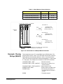
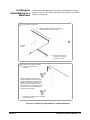
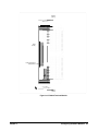
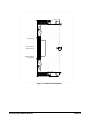
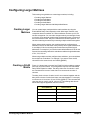
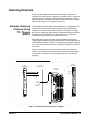
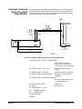
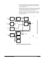
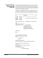
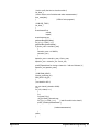
Creating Larger
Matrixes with
Multiple Mainframes
Figure 2-14 shows one way to connect C-Size mainframes together using
GPIB. The matrix switch modules in each mainframe are then configured as
switchboxes. The switchbox card numbers are 1, 2, 3, etc. in each
mainframe and each mainframe has a different address.
For example, to address the second module in the second mainframe, use
OUTPUT 70815; "CLOSe (@20001)", where the interface select code is 7,
the command module primary address is 08, and and the matrix module's
secondary address is 15. This address selects card 2, row 00, column 01.
E1406A
Command Module
(Primary Address = 09)
E1466A (Logical Address = 120. Secondary Address = 15)
E1406A
Command Module
(Primary Address = 08)
E1466A (Logical Address = 120. Secondary Address = 15)
E1406A
Command Module
(Primary Address = 07)
E1466A (Logical Address = 120. Secondary Address = 15)
E1466A (Logical Address = 121)
E1466A (Logical Address = 122)
E1466A (Logical Address = 121)
E1466A (Logical Address = 122)
E1466A (Logical Address = 121)
E1466A (Logical Address = 122)
GPIB
Figure 2-14. Creating Larger Matrixes with Multiple Mainframes
34 Configuring the Matrix Modules
Chapter 2