1
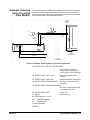
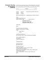
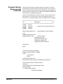
This BASIC example program sets up the multimeter (GPIB address 70903)
to scan making two-wire resistance measurements. The E1465A matrix
module is set to scan row 00, columns 00 to 15.
10 ALLOCATE REAL Rdgs(1:16)
20 OUTPUT 70915; "*RST;*CLS"
! Reset and clear the matrix
module
30 OUTPUT 70903; "*RST;*CLS"
! Reset and clear the multimeter
40 OUTPUT 70903; "ABORT;:TRIG:SOUR TTLTRG0"
! Multimeter triggers on TTL
Trigger line 0
50 OUTPUT 70903; "OUTP:TTLTRG1:STAT ON"
! Multimeter pulses TTL Trigger
line 1 on measurement
complete
60 OUTPUT 70903; "CONF:RES AUTO,DEF"
! Set multimeter function to
Resistance
70 OUTPUT 70903; "TRIG:DEL 0;COUN 16;:CAL:ZERO:AUTO ON"
! Set multimeter Range, NPLC
functions
80 OUTPUT 70903; "*OPC?"
90 ENTER 70903; Check
! Check to see if multimeter ready
100 OUTPUT 70903; "INIT"
! When multimeter is ready,
initialize trigger
110 OUTPUT 70915; "TRIG:SOUR TTLTRG1"
! Set matrix module to be
triggered by TTL Trigger line 1
120 OUTPUT 70915; "OUTPUT:TTLT0:STATE ON"
! Matrix module pulses TTL
Trigger line 0 on channel closed
130 OUTPUT 70915; "SCAN (@10000:10015
! Scan list is Row 0, Columns
0 to 15
140 OUTPUT 70915; "INIT"
! /nitiate scan
150 OUTPUT 70903; "FETCH?"
160 ENTER 70903; Rdgs(*)
! Enter readings
170 PRINT Rdgs(*)
! Print readings
180 END
40 Using the Matrix Modules
Chapter 3