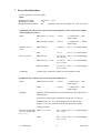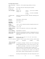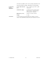
1
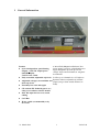
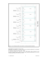
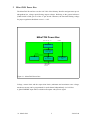
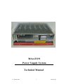
MAraTON
Power Supply System
Technical Manual
21. March 2012
1
*01695.A0
General Remarks
The only purpose of this manual is a description of the product. It must not be interpreted as
a declaration of conformity for this product including the product and software.
W-Ie-Ne-R revises this product and manual without notice. Differences of the description in
manual and product are possible.
W-Ie-Ne-R excludes completely any liability for loss of profits, loss of business, loss of use
or data, interrupt of business, or for indirect, special incidental, or consequential damages of
any kind, even if W-Ie-Ne-R has been advises of the possibility of such damages arising
from any defect or error in this manual or product.
Any use of the product which may influence health of human beings requires the express
written permission of W-Ie-Ne-R.
Products mentioned in this manual are mentioned for identification purposes only. Product
names appearing in this manual may or may not be registered trademarks or copyrights of
their respective companies.
No part of this product, including the product and the software may be reproduced,
transmitted, transcribed, stored in a retrieval system, or translated into any language in any
form by any means with the express written permission of W-Ie-Ne-R.
Control Cabinet
In the context of this user manual, the control cabinet must fulfill the requirements on fireprotective enclosures according to EN 60950 / IEC 60950 / UL 60950.
All devices are intended for operation in control cabinets or in closed areas. The LAN
connection and all wire connections between the different system parts must be done via
shielded cable with conductive connector shells, which are fixed with screws.
Furthermore, an additional fire-protective enclosure is required which must not affect proper
air circulation.
Mains Voltage and Connection
The Power supplies are equipped with a “World”- mains input (rated voltage range: 100-240
VAC, frequency: 50-60 Hz, rated current: 16 A). Before connecting to the mains please
double-check correspondence.
This is a permanently connected equipment. Mains input connection at the power supply
primary rectifier is done with screw terminals. A combined circuit breaker / main switch
(16A at maximum operating temperature) is included.
Before working at the terminals, the power mains to which the device shall be connected
must be absolutely reliable switched off or disconnected.
21. March 2012
i
*01695.A0
The DC output terminals are connected to hazardous voltage. After disconnecting the mains
the capacitors connected to the DC-outputs must be discharged by a well isolated resistor 22
Ohm, 10 Watt.
Terminal Label
+
PE
L
N
Description
Positive DC Output
Negative DC Output
Protective Earth
Phase
Return, Neutral
Color of the Wire
green/yellow
black or brown
blue
Connection to Earth
Safety
After connecting the Power box to the mains, the mains input module is powered
permanently. Filter and storage capacitors of the power factor correction module are charged
with about 400VDC. Any DC-On-Signal as well as a power switch at control board (if any
installed) operates as a low voltage DC on/off switch only and not as a mains breaker.
Therefore it becomes dangerous if the box cover is open. In this case a lot of
components on high voltage potential get touchable!
Before starting any kind of work inside the power box remove the unit from
mains and wait a couple of minutes with your activities! Discharge the primary
DC Filter-capacitors by use of a well isolated 22 ohm 10W resistor.
We recommend in case of any malfunction to send the power box to Wiener or
to one of our representative for service
21. March 2012
ii
*01695.A0
Declaration of Conformity
Low Voltage Directive 73/23/EEC and EMC Directive Art. 10.1 of 89/336/EEC
W-Ie-Ne-R
Plein & Baus GmbH
declare under our own responsibility that the product
MAraTON Power Supply System
Items: 0M01; 0M02; 0M05; 0PFC
is in accordance with the following standards or standardized documents:
1.
EN 60 950-1:2001
+ Corr:2004-09
2.
EN 61 000-6-3:2001
EN 55 022:1998
+ Corr:2001 + A1:2000 Kl. B
EN 55 022:1998
+ Corr:2001 + A1:2000 Kl. B
EN 61 000-3-2:2001
EN 61 000-3-3:1995 +Corr:1997 +A1:2001
EN 61 000-6-2:2001
EN 61 000-4-6:1996 + A1:2001
EN 61 000-4-3:1996 + A1:1998 + A2:2001
3.
EN 61 000-4-4:1995 + A1:2001
EN 61 000-4-5:1995 + A1:2001
EN 61 000-4-11:1994 + A1:2000
EN 61 000-4-2:1995 + A1:1998 + A2:2001
Niederspannungsrichtlinie [low voltage
directive]
Störaussendung EMA [RF emission]
Störspannung [conducted noise]
Störfeldstärke [radiated noise]
Oberschwingungen [harmonics]
Spannungsschwankungen [flicker]
Störfestigkeit EMB [immunity]
HF-Einströmung [injected HF currents]
HF-Felder [radiated HF fields] incl.
”900MHz”
Burst
Surge
Spannungs-Variationen [voltage
variations]
ESD
Conditions:
This unit is not a final product and is foreseen for use inside a closed cabinet. The supplying
of loads over long distances (>3m) needs possibly additional RF rejection hardware to get in
conformity of the definition.
Name and signature of authorized person
Place and Date
Juergen Baus
Techn. Director
Mai. 2008
21. March 2012
iii
*01695.A0
Contents
Declaration of Conformity...............................................................................................iii
1 General Information...............................................................................................................1
2 Primary Rectifier....................................................................................................................3
3 MAraTON Power Box...........................................................................................................5
3.1 High Voltage DC Input.................................................................................................6
3.2 Water Cooling Connection...........................................................................................7
3.3 Main Switch...................................................................................................................7
3.4 Control Connector Input.............................................................................................7
3.5 Connection of a Personal Computer............................................................................8
3.6 Control via CAN-Bus....................................................................................................9
3.7 Control of the Power Supply without PC....................................................................9
3.8 Control of the Power Supply by the “Main Switch”................................................10
4 Power Supply Adjustments..................................................................................................10
5 The Power Bin......................................................................................................................11
5.1 Temperature Probes....................................................................................................12
5.2 Sense Connection.........................................................................................................12
5.3 Status LED...................................................................................................................13
5.4 ON Jumper...................................................................................................................13
5.5 RS232............................................................................................................................14
5.6 CAN..............................................................................................................................14
6 Output Register (Optional)...................................................................................................15
7 Power Box Data Sheet..........................................................................................................17
8 Primary Rectifier Data Sheet................................................................................................20
9 Appendix A: Ordering Information......................................................................................21
9.1 Power Box....................................................................................................................21
9.2 Primary Rectifier.........................................................................................................22
10 Appendix A: Recommended Cable Specification..............................................................23
10.1 400V DC Cabling (Primary Rectifier ↔ MAraTON)............................................23
21. March 2012
iv
*01695.A0
Figures
Figure 1.1: MARATON System Overview..................................................................2
Figure 2.1: Primary Rectifier......................................................................................3
Figure 2.2: 4U Primary Rectifier Power Bin fox six Primary Rectifier Modules...........4
Figure 3.1: MAraTON Power Box..............................................................................5
Figure 3.2: Power Box Front......................................................................................6
Figure 3.3: Power Box Rear Side (Power Output Connections)...............................6
Figure 3.4: Programming of the Control Connector Behavior....................................8
Figure 3.5: Connection of a Personal Computer........................................................8
Figure 5.1: Power Bin Pin Assignment....................................................................11
Figure 5.2: Sense Connection Connectors..............................................................12
Figure 6.1: Output Register Schematic (one of 32)..................................................15
Figure 6.2: Output Register Connectors..................................................................15
Figure 10.1: HV DC Wiring......................................................................................23
Tables
Table 1: High Voltage DC Input Connector Pin Assignment......................................6
Table 2: Control Connector Pin Assignment..............................................................7
Table 3: CAN Transmission Speed Index..................................................................9
Table 4: Power Supply Adjustment with the Rotary Switches..................................10
Table 5: Sense Connection Jumper Settings...........................................................13
Table 6: Status LED Jumper Settings......................................................................13
Table 7: ON Jumper Settings..................................................................................13
Table 8: Bin RS232 Connector Pin Assignment......................................................14
Table 9: Bin CAN Connector Pin Assignment..........................................................14
Table 10: Inhibit Connector Pin Assignment............................................................16
21. March 2012
v
*01695.A0
1
General Information
Features
● up to 8 independent, quasi-floating
outputs, >3 kW DC output power
(385VDC input),
3.6 kW water cooled
A MAraTON (Magnetism Tolerant New
power supply system) is a distributed power
supply designed to provide up to 8 low
voltage / high current channels at magnetic
environment.
Fully controlled, adjustable trip levels It offers up to 8 channels in a 3U high box.
● Adjustable voltages, current limits and Dynamic behavior adjustable by internal
jumper (long or short sensed distances to
OVP-trip levels
loads).
● Extremely low noise and ripple
●
●
CE conform EN 50 081/82 part 2 or 1,
safety in accordance with EN 60 950
●
385V DC input for low cross section
cabling
●
CAN-Bus
●
Water cooled (recommended) or by
forced air
21. March 2012
1
*01695.A0
The power supply system is consisting of two main components
●
Primary Rectifier
●
Power Box
MAraTON System Overview
Mains Input
CAN Bus
Primary Rectifier
Input: 230V AC ± 10%
Output: 385V DC, regulated
„Safe“ Environment
„Hostile“ Environment
MAraTON Power Box
Up to 8 Quasi-Floating DC/DC Converter Channels
Figure 1.1: MARATON System Overview
The Primary Rectifier is operating at locations with standard industrial conditions (Safe
Environment).
The Power Box is located near to the electronics which shall be supplied, and is capable to
operate in a “Hostile Environment” (strong magnetic field).
The distance between the DC/DC-Converter and the other components may be up to 120 m.
21. March 2012
2
*01695.A0
2
Primary Rectifier
This module converts the standard mains voltage (100 V ... 230 V AC, 16 A) to a regulated
DC voltage (nominal 385 V). There is no galvanic isolation.
Up to 6 Primary Rectifiers can be plugged into one Primary Rectifier Bin.
Primary Rectifier Bin
Input: 230/400 V AC, 3 Phase, max.
32 A, max. 22 kW
AC Input / DC Output Terminals
Primary Rectifier
EMI Input Filter
Rectifier + PFC
Boost Converter with
Power Factor Corection
EMI Output Filter
Output: 385V DC
6 fold 9 A, 21 kW
Figure 2.1: Primary Rectifier
The screw terminal connections to the mains are separate for each Primary Rectifier. So it is
possible to connect all 6 inputs in parallel to a 230V/96A mains connection. Another
solution is to connect each two modules in parallel, and connect the three groups in a star
connection to a 400V/230V mains (The central point conductor must be provided!).
The screw terminal connections of the high voltage DC outputs may not be connected in
parallel. Each output shall be routed to one (or max. two in a low power configuration)
Power Box.
Before working at the terminals, the power mains to which the device is
connected must be absolutely reliable switched off or disconnected.
The DC output terminals are connected to hazardous voltage. After
disconnecting the mains the capacitors connected to the DC-outputs must
be discharged by a well isolated resistor 22 Ohm, 10 Watt.
21. March 2012
3
*01695.A0
Figure 2.2: 4U Primary Rectifier Power Bin fox six Primary Rectifier Modules
The conductor cross section is max. 2.5 mm²,
PR-Modules are plugged to a six-fold rear plug/screw terminal combination. The terminals
are foreseen for wire cross section of max. 2.5mm².
For different paralleled DC outputs the version 0PFC0.000P without integrated circuit
breaker is available. In that case the AC inputs of the paralleled PR-Modules have to be the
same phasing. Otherwise a short circuit occurs.
21. March 2012
4
*01695.A0
3
MAraTON Power Box
The MAraTON Power Box uses the 385 VDC of the Primary Rectifier and generates up to 8
independent low voltage quasi-floating output voltages. Referring to the ground reference
(VME-LOGIC-GND, pin 30 of the 37 pin D-Sub connector) the maximal floating voltage
for proper regulation should not exceed +/-10V.
MAraTON Power Box
Input: 385 V DC, 11 A
CAN-Bus
EMI Input Filter
Rectifier
for non-RAD operation
with AC supply
385 V DC
Auxiliary Power
DC-DC Converter
MDC
max. 8 Channels
Converter Control
and Observation
MUH
Output: Up to 8
quasi-floating
channels
Figure 3.1: MAraTON Power Box
Voltage, current limit and the supervision limits (minimum and maximum sense voltage,
maximum current) can be programmed for each channel independently via CAN-bus.
A global INHIBIT input allows to disable all outputs with just one signal.
21. March 2012
5
*01695.A0
Figure 3.2: Power Box Front
Figure 3.3: Power Box Rear Side (Power Output Connections)
3.1
High Voltage DC Input
The DC input connections are made with the Amphenol circular connector series ECTA 133
(standard polarization: 0° rotation between insert and shell).
We recommend the mating plug 1331-M-303-FS with the backshell 1330-3-PES1.
DC Input
Pin Signal
Comment
1
2
PE
DC Power Input. There is a bridge rectifier inside, so exchange of
the polarity does not harm.
Safety Ground
+ 385 V
+ 385 V Return
Protective Earth
Table 1: High Voltage DC Input Connector Pin Assignment
21. March 2012
6
*01695.A0
3.2
Water Cooling Connection
The water connections are made with quick couplings series LC 6.4 mm from Colder
Products Company (CPC). We recommend an elbow mating plug with shutoff, e.g.
LCD230-04.
Consider that water inlet and water outlet are not exchangeable.
The safety valve may not be readjusted by the customer.
3.3
Main Switch
The green illuminated switch works as a global inhibit input.
3.4
●
0
Power outputs disabled
●
I
Switch is lighting, power outputs may be enabled by the remote control.
Control Connector Input
The power inhibit input (POWER) is provided to force all outputs to be switched off. The
default configuration is:
●
connected to GND
Power outputs disabled
●
floating
Power outputs may be enabled by the remote control
DSUB15 female
Pin Signal
Comment
8
15
7
14
6
13
5
12
4
11
3
10
2
9
1
reserved
reserved
reserved
reserved
reserved
reserved
reserved
reserved
Ground of the aux. supply, connected to DGND
reserved
Inhibit input
reserved
reserved
reserved
reserved
NC
NC
NC
+5V INTERLOCK
NC
GLOBAL_TRIPOFF_DISABLE
NC
INTERLOCK_RETURN
GND
CAN-H
INHIBIT
CAN-L
NC
CAN-GND
NC
Table 2: Control Connector Pin Assignment
This default configuration can be changed with the RS232 configuration software (see
manual 00461.A0)
21. March 2012
7
*01695.A0
Figure 3.4: Programming of the Control Connector Behavior
The signals shall be connected by an isolated contact (e.g. relays), and must not be connected
to other potentials.
3.5
Connection of a Personal Computer
Equipment: A PC running Windows, the control program and a simple adapter.
This RS232 connection is intended for setup and repair operation and should not be used for
permanent monitoring during normal operation.
9 Pin DSUB female
9 Pin DSUB male
(PL 500 F8)
(PC)
3
2
8
3
7
1 kΩ
Ω
5
6
1 kΩ
Ω
100nF
Figure 3.5: Connection of a Personal Computer
21. March 2012
8
*01695.A0
Note:
If you use Pin 3 and 8 for a serial connection to a computer, you can’t use this pins any more
for the „Remote On“ and „Status Out“ functions and you can neither connect the power
supply to an alphanumeric control panel (see below 4) nor operate with remote on / off (see
below 3).
3.6
Control via CAN-Bus
The CAN Bus Signals are provided on the 9 Pin DSUB of the power supply.
This pinning is NOT identical to the 9-pin DSUB of the power bin!
CAN_H:
Pin 5
CAN_L:
Pin 9
CAN_GND:
Pin 4
The software protocol is described in a separate document (Part No *00183)
Index
0
1
2
3
4
5
6
7
8
9
Max. Distance
10 m
40 m
130 m
270 m
530 m
620 m
1.300m
3.300 m
6.700 m
10.000 m
Bit Rate
1.6 Mbit/s
1.0 Mbit/s
500 kbit/s
250 kbit/s
125 kbit/s
100 kbit/s
50 kbit/s
20 kbit/s
10 kbit/s
5 kbit/s
Type
high- speed
(needs termination)
low-speed
Table 3: CAN Transmission Speed Index
3.7
Control of the Power Supply without PC
There is a remote on/off input and a status output function:
Remote On:
9 Pin DSUB: Close a “make” contact or switch between Pin 8 (Serial Data
In) and Pin 2 or 7.
Status Output: 9 Pin DSUB: Connect a LED between Pin 3 (Serial Data Out,+) and Pin 1 or
6.
21. March 2012
9
*01695.A0
3.8
Control of the Power Supply by the “Main Switch”
Use “mains switch” at the rear side to start the power supply.
Also this optional rocker switch acts as a DC on / off switch and doesn’t disconnect mains
from the unit!
4
Power Supply Adjustments
All output voltages can be adjusted manually via the two rotary switches situated on the
power supply top.
1. the 1. rotary switch selects the function which has to be adjust
2. the 2. rotary switch will change the settings when turned (right/left = +/-)
Channel selection
(0:Uo...7:U7)
(A-D: CANbus)
Adjustment
+
Mode
Function
Selection
0-7
Adjust Voltage of U0-U7
A
CAN Address (low, Bit 0-3)
B
CAN Address (high, Bit 4-6)
C
CAN General Call Address (low, Bit 0-3)
D
CAN General Call Address (high, Bit 4-6)
E
CAN Transmission Speed Index
Table 4: Power Supply Adjustment with the Rotary Switches
To change the CAN-Bus parameters, the following sequence is recommended (Example:
address 58 = 0x3A, general call address 127 = 0x7F, transmission speed index 1):
1. Set the MODE to “A”
2. Set the ADJUST to the low address value (“A”)
3. Set the MODE to “B”
4. Set the ADJUST to the high address value (“3”)
5. Set the MODE to “C”
21. March 2012
10
*01695.A0
6. Set the ADJUST to the low G. Call address value (“F”)
7. Set the MODE to “D”
8. Set the ADJUST to the high G. Call address value (“7”)
9. Set the MODE to “E”
10. Set the ADJUST to the speed index (“1”)
11. Set the MODE to “F” (park position)
5
The Power Bin
For easy exchange of the MAraTON Power Box the special bin is provided: The low
voltage/high current cabling is connected to M8 (pin 1..9 and 12) and M6 (pin 10, 11 and
13..18) threaded bolts (MULTICONTACT).
18
15
12
9
6
3
-
+
-
+
-
+
Sense
17
14
11
8
5
2
Connection
-
-
-
-
-
-
Board
16
13
10
7
4
1
+
+
+
+
+
+
Figure 5.1: Power Bin Pin Assignment
21. March 2012
11
*01695.A0
Figure 5.2: Sense Connection Connectors
5.1
Temperature Probes
Up to 8 temperature probes (Silicon sensor KTY81-110) may be connected to the T0/T0R ...
T7/T7R terminals).
5.2
Sense Connection
The sense lines (terminal U0+/U0- ... U7+/U7-) must be connected to the power output lines
at the load for propper regulation.
The sense difference amplifiers of all power modules are connected to a common auxiliary
power supply. This amplifiers have a specific measurement range (input common mode),
and it must be satisfied that all sense voltages remain inside this common mode operating
range.
To achive this either the positive or negative sense line of each channel must be connected to
the digital ground (DG).
This connection can be made by setting a jumper at the 3-pin jumper posts DG0...DG7:
21. March 2012
12
*01695.A0
-DG+
Negative sense line connected to digital ground.
Positive sense line connected to digital ground.
Table 5: Sense Connection Jumper Settings
5.3
Status LED
The green STATUS LED displays the status of the power supply.
●
OFF
Power is off
●
ON
Power is on
●
BLINKING
Any Failure
The status line of the power supply is shared with the serial (RS232) communication. The
functionallity is selected with the C/LED jumper:
C/LED
RS232 communication active, LED unused
LED active, no RS232 communication possible
Table 6: Status LED Jumper Settings
5.4
ON Jumper
It is possible to switch the power supply on without remote control.
The power on line of the power supply is shared with the serial (RS232) communication.
The functionallity is selected with the ON jumper:
ON
RS232 communication active
POWER ON, no RS232 communication
Table 7: ON Jumper Settings
21. March 2012
13
*01695.A0
5.5
RS232
DSUB9 female
Pin Signal
Comment
1
6
2
7
3
8
4
9
5
reserved
reserved
TXD output of the power supply
reserved
RXD input of the power supply
reserved
reserved
reserved
GND
NC
NC
TXD
NC
RXD
NC
NC
NC
GND
Table 8: Bin RS232 Connector Pin Assignment
5.6
CAN
DSUB9 male
Pin Signal
Comment
1
6
2
7
3
8
4
9
5
reserved
reserved
CAN-bus LOW signal
CAN-bus HIGH signal
CAN-bus GND
reserved
reserved
reserved
reserved
NC
NC
CAN-L
CAN-H
CAN-GND
NC
NC
NC
NC
Table 9: Bin CAN Connector Pin Assignment
21. March 2012
14
*01695.A0
6
Output Register (Optional)
This is a special option designed for the CERN CMS experiment.
In addition of the elements of the standard sense connection board this circuit provides 32
quasi-floating digital outputs, which can be set via CAN-bus.
Figure 6.1: Output Register Schematic (one of 32)
The +15VAUX_RETURN of the auxiliary power supply is connected to the digital ground
(DG) inside of the power supply.
For the functionallity of this circuit it is essential to connect the sense lines with the digital
ground, too (see 5.2 Sense Connection on page 12).
21. March 2012
15
*01695.A0
Figure 6.2: Output Register Connectors
DSUB37 male
Pin
1
20
2
21
3
22
4
23
5
24
6
25
7
26
8
27
9
28
10
29
11
30
12
31
13
32
14
33
15
34
16
35
17
36
18
37
19
X1
INHIBIT 16
INHIBIT RETURN 16
INHIBIT 17
INHIBIT RETURN 17
INHIBIT 18
INHIBIT RETURN 18
INHIBIT 19
INHIBIT RETURN 19
INHIBIT 20
INHIBIT RETURN 20
INHIBIT 21
INHIBIT RETURN 21
INHIBIT 22
INHIBIT RETURN 22
INHIBIT 23
INHIBIT RETURN 23
INHIBIT 24
INHIBIT RETURN 24
INHIBIT 25
INHIBIT RETURN 25
INHIBIT 26
INHIBIT RETURN 26
INHIBIT 27
INHIBIT RETURN 27
INHIBIT 28
INHIBIT RETURN 28
INHIBIT 29
INHIBIT RETURN 29
INHIBIT 30
INHIBIT RETURN 30
INHIBIT 31
INHIBIT RETURN 31
NC
NC
NC
NC
NC
X0
INHIBIT 0
INHIBIT RETURN 0
INHIBIT 1
INHIBIT RETURN 1
INHIBIT 2
INHIBIT RETURN 2
INHIBIT 3
INHIBIT RETURN 3
INHIBIT 4
INHIBIT RETURN 4
INHIBIT 5
INHIBIT RETURN 5
INHIBIT 6
INHIBIT RETURN 6
INHIBIT 7
INHIBIT RETURN 7
INHIBIT 8
INHIBIT RETURN 8
INHIBIT 9
INHIBIT RETURN 9
INHIBIT 10
INHIBIT RETURN 10
INHIBIT 11
INHIBIT RETURN 11
INHIBIT 12
INHIBIT RETURN 12
INHIBIT 13
INHIBIT RETURN 13
INHIBIT 14
INHIBIT RETURN 14
INHIBIT 15
INHIBIT RETURN 15
NC
NC
NC
NC
NC
Comment
reserved
reserved
reserved
reserved
reserved
Table 10: Inhibit Connector Pin Assignment
21. March 2012
16
*01695.A0
7
Power Box Data Sheet
3U box with max. 6 power modules.
Input:
Rated Input Voltage:
Rated Input Current:
Output Insulation (SELF)
385 V DC +/- 10 V
11 A
CE
EN 60950 , ISO 380, VDE 0805, UL 1950, C22.2.950
Regulation fast remote sense circuit (short sensed distance, sense connected to output
at the MARA power bin):
Static:
Dynamic (0.5 m
wire):
Recovery Time:
Conditions
MDC/M 2-8 V / 30–60
V
< 15 mV
(+/-100% load, +/- full
mains range)
MDC/M other voltages
< 0.05 %
(+/-100% load, +/- full DC
input range)
MDC/M 2-8 V
< 100 mV
(50 % - 75 % load change)
other
< 0.7 %
(50 % - 75 % load change)
MDC/M 2-8V
1%: 0.2 ms (50 % - 75 % load change)
0.1%: 0.5 ms
MDC/M 5-16V, 7-24V
1%: 0.0 ms (50 % - 75 % load change)
0.1%: 1.0 ms
MDC/M 30-60V
1%: 0.5 ms (50 % - 75 % load change)
0.1%: 1.0 ms
Current slope <1000A/ms, 20mF per 100A parallel to load
Regulation slow remote sense circuit (long sensed distance):
Static:
Dynamic:
MDC/M 2-8V/ 30-60V
< 15 mV
(+/-100% load, +/- full
mains range)
Other
< 0.05 %
(+/-100% load, +/- full
mains range)
Dynamic deviation depends on current slope resp. filter capacitors at
load side only
30m cable to load, 0,3mF capacitance at load side, 1V drop at
nominal load, 10% - 90 % load change with 3ms slope (50A
output= 13,33A/ms) leads to less than 10% temporary output
voltage deviation
Recovery Time (40m MDC 2-7V, 2-8V
wire, 5V at load side,
Udrop < 2 V:
Other
21. March 2012
10%: <15 ms (50 % - 75 % load change)
1%: <25 ms
10%: <15 ms (50 % - 75 % load change)
1%: < 33 ms
17
*01695.A0
DC Output Characteristics:
Sense compensation
range:
Limited to < 10V or nominal voltage (whichever is lower).
Regulation mode:
The voltage at the sense connection point is regulated.
Floating range:
min. +/-10V
Noise and ripple:
Voltage < 8 V
Voltage > 8 V
< 10 mVPP
< 15 mVPP
(0.5 m wire, 0–20 MHz)
< 3 mVPP
(10 m wire, 0-300 MHz)
< 1.5 mVRMS
Conditions at the
load:
Parallel (X) 330µF and 1µF ceramic, 100nF HF- conducting to case
(Y) each line
Emission:
CE EN 50081-1 (EN 55 022-B)
Immunity:
CE EN 50082-1 or 2
Operating
temperature:
10 °C – 40 °C
Storage
Temperature:
- 30 °C - + 85 °C (cooling water must be completely removed, else
+3 °C - +85 °C)
Temp.- Coefficient: < 0.2% / 10K
Stability (constant
conditions)
<5mV or 0.1% within 24 h, <25mV or 0.3% within 6 months
Current limiting:
Programmable via CAN bus.
Status control / DC
Off (trip off):
Processed in external Remote Controller. Tripping global, group- or
channel wise programmable (after overload, overheat , overvoltage,
undervoltage)
Efficiency (pro
Module):
65% 2V/ -81% >5V/ -85% >7V -87% >12V/ -90% >48V at
nominal input voltage
M T B F, cooled by: Conditions: 3kW DC output with 80% efficiency (600W internal
power
dissipation:
WORST
CASE)
Water, 30°C inflow:
Forced Air, 30°C
entrance:
ca. 120,000 h , put through > 50l/h for <10°C DT of cooling water.
Minimum differential pressure >0.5 bar, abs. max. pressure <15bar
ca. 90,000 h , put through > 153m3/h for <15°C DT of cooling air,
ambient air pressure 1 bar. Adequate airflow is roughly 1,4m/s.
Values for air cooled units are valid for new ones. Abrasive dust,
corrosion, etc. can limiting the heat transfer to the cooling air
during lifetime. Higher operating temperature is the consequence.
Increasing of internal temperater at the most critical points of 10°C
21. March 2012
18
*01695.A0
will reduce the MTBF by 50% Lower operating temperatures will
increase the MTBF accordingly, independent of cooling medium.
Construction
features,
Accessories:
Accessories:
21. March 2012
3 U box with extraction
lever:
max. 6 modules, up to 3 kW / 3,6kW
output power
Connections / plugs:
24 female pins 80A, parallel used for
higher currents, 3 x 9pin Sub D for
sensing (each for 4 channels)
Dimensions (w, h, d)
434 mm x 132 mm x 325 mm
Weight:
31,5 kg
19" Power Bin for plug in MAraTON power supplies. 18 power
contacts with M6/M8 threated bolts and sense terminals at rear side.
19
*01695.A0
8
Primary Rectifier Data Sheet
Mains Input
AC Input:
power fact. >0,98
CE
100- 240VAC / 16A +/-10% (20A peak), 47-63Hz,
Inrush current:
(cold unit)
limited by soft start-circuit to 110% of nominal current
Input protection:
Circuit breaker with 20A thermal overload protection
(16 A at maximum operating temperature) included.
Power Output:
converter
385 V DC +/- 5V, matched for MARATON DC/DC
continuously 9A, 3500W nominal (4,4kW peak) @
230VAC input
Regulation:
Load (10-90%)
Mains (10-90%)
1% deviation
1% deviation
Output ripple:
frequency)
Load (10-90%)
1-10Vss 94-126Hz (double mains
RF rejection:
EN 55 022 Class B, Input and Output
Output protection
overload:
current limiting for booster circuits, 90°C cut off
temperature
Dimensions:
4U x 14 PU width acc. to IEC 60297, 450 mm deep
Weight:
4,7 kg
Module connectors:
2mm pin / socket diameter.
max. ratings: 25A up to 50°C, 500V. 2,2kV test
voltage 50Hz
PE / Ground pins outfitted as leading pin
EMC Compatibility /RFI Rejection
Separate Input and Output
EMC Filter
EMA
EN 61 000-6-3:2001
[RF emission]
EN 55 022:1998 + Corr:2001 + A1:2000 Class B
conducted noise
EN 55 022:1998+ Corr:2001 + A1:2000 Class B
radiated noise
EN 61 000-3-2:2001
harmonics
EN 61 000-3-3:1995 +Corr:1997 +A1:2001
flicker
EMB
EN 61 000-6-2:2001
[immunity]
EN 61 000-4-6:1996 + A1:2001
EN 61 000-4-3:1996 + A1:1998 + A2:2001
EN 61 000-4-4:1995 + A1:2001
EN 61 000-4-5:1995 + A1:2001
EN 61 000-4-11:1994 + A1:2000
EN 61 000-4-2:1995 + A1:1998 + A2:2001
injected HF currents
radiated HF fields incl. 900MHz
Burst
Surge
voltage variations
ESD
Operation temperature:
0....50°C without derating, storage: -30°C … + 85°C
Efficiency:
better than 95 %
MTBF
electronics:
40°C ambient: ca. 100 000 h
integrated fan:
40°C ambient: ca. 65 000 h, 25° ambient >85000h
21. March 2012
20
*01695.A0
9
9.1
Appendix A: Ordering Information
Power Box
The power boxes can be classified into four categories, which define the most significant
part of the ordering number:
With magnetic screening (120 mT external field):
Standard
Output Register Option
Air Cooled
0M01.xxxx
0M01.xxxxR
Water Cooled
0M02.xxxx
0M02.xxxxR
Standard
Output Register Option
0M05.xxxx
0M05.xxxxR
Without magnetic screening:
Water Cooled
The right side of the ordering number is not descriptive, it is randomly assigned to the
requested module & options configuration. Up to six power modules may be used inside of
one power box.
The following modules are possible:
Module Type
Channels per
Optimal Voltage
Peak Output
Continuous
Module
Range
Current
Output Power
MDC
2
2V ... 7V/8V
2*55A
2*300W
MDC
2
5/7V ... 15/16V
2*22A
2*300W
MDC
2
9V
2*30A
2*270W
MDC
2
7V ... 24 V
2*11.5A
2*250W
MDC
2
30V ... 60V
2*6.6A
2*300W
The MDC 7V and MDC 9V are available with the special “maximum voltage ensured”
option.
With this option the modules are designed in a way that even in the worst case (All
electronic regulation and protection fails and the PWM generates it's maximum duty cycle)
the output voltage does not rise. Please contact WIENER for more details.
All power modules can be ordered with different sense regulation characteristics:
21. March 2012
21
*01695.A0
●
Fast
Fastest regulation, but may be instable if connected to cables longer
than 1 m.
●
Moderate
This is the standard configuration for cable length up to 30 m
●
Slow
This is used for much longer cables
Available Power Bins:
Ordering Number
9.2
Power Bin (MARA) 3U
0B15.1200
Power Bin (MARA) 6U, for two power boxes
0B14.2400
Primary Rectifier
Ordering Number
Primary Rectifier Module (PFC)
0PFC.0001
Power Bin for 6 PFC Modules
0B07.0001
21. March 2012
22
*01695.A0
10 Appendix A: Recommended Cable Specification
10.1 400V DC Cabling (Primary Rectifier ↔ MAraTON)
The cable selections are based on max. 10V voltage drop at the cable, at max. current of 10A
(total cable resistance ≤ 1 Ω)
maximum
number of wires / LAPP part no.1
LAPP
length
cross section
not halogen-free
halogen-free
40 m
2 x 1.5 mm²
1135 902
2X1,5
0035 067 2X1,5
65 m
2 x 2.5 mm²
1135 402
2X2,5
80 m
4 x 1.5 mm² (2 1135 904
4X2,5
0035
wires in parallel)
no.2
part
070
4G1,5
(standard cable only with
gn/ye color)
105 m
2 x 4 mm²
1135 502
130 m
4 x 2.5 mm² (2 1135
wires in parallel)
2X4,0
404
(standard
4G2,5 0035
cable
only (standard
available with gn/ye color)
160 m
2 x 6 mm²
1135 602
up to 1.5m,
unscreened
090
4G2,5
cable
only
available with gn/ye color)
2X6,0
up to 1.5m,
unscreened
up to 160 m,
screened
Patch
Pannel
Patch
Pannel
Primary
Rectifier
MARATON
Safety Earth
Figure 10.1: HV DC Wiring
1 ÖLFLEX® CLASSIC 110 CY, U0/U: 300/500 V, Datasheet:
http://www.lappkabel.de/webkatalog/katalog.cfm?cmd=show_produkt_details&produkt_id=10016
2 ÖLFLEX® CLASSIC 110 CH, U0/U: 300/500 V, Datasheet:
http://www.lappkabel.de/webkatalog/katalog.cfm?cmd=show_produkt_details&produkt_id=10035
21. March 2012
23
*01695.A0