1
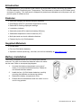
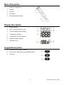
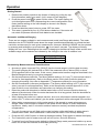
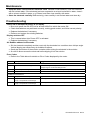
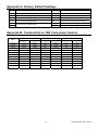
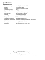
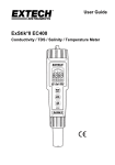
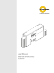
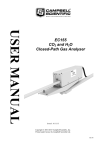
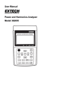
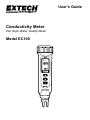
User's Guide Conductivity Meter Pen Style Water Quality Meter Model EC100 Introduction Congratulations on your purchase of the Extech Pen Style Water Quality instrument; the Model EC100 measures Conductivity and Temperature. The instrument is housed in an IP65 Water-proof enclosure for safety. This instrument is shipped fully tested and calibrated and, with proper use, will provide years of reliable service. Features Automatic Ranging and Manual Ranging capability Dual Display with ATC (automatic temperature control) Data hold for freezing displayed readings Low battery indicator Automatic power-off for maximum battery efficiency Switchable temperature units of measure (C/F) Multi-point and one-touch calibration features Powered by four (4) LR44 batteries Supplied Materials EC100 meter Four (4) LR44 button batteries Operation manual (hard copy, mini-disk, and on-line availability at www.extech.com) Battery Installation The meter is shipped with the four (4) LR44 button batteries removed. The user must install the batteries before the meter can be used. Refer to accompanying diagram. 1. Unscrew the battery compartment cover (top of meter) in a counter-clockwise direction. Please do not discard the black washer. 2. Install the four (4) LR44 button batteries, carefully orienting the batteries and observing polarity. 3. Replace the battery compartment cover. 4. Please remove the batteries while the meter is not in use for long periods. 2 EC100-EU-EN v2.2 06/13 Meter Description 1. Battery Compartment 2. Display 3. Keypad 4. Electrode 5. Electrode protective cap Display Description 1. Data Hold icon 2. Micro- and milli-Siemens units 3. Primary measurement reading 4. Temperature reading 5. Temperature units of measure 6. Battery strength indicator 7. Calibration icon Keypad Description 1. Power ON-OFF and SET button 2. Down Arrow, Data Hold, and Calibration button 3. Up arrow 3 EC100-EU-EN v2.2 06/13 Operation Getting Started 1. Remove the probe’s protective cap (bottom of meter) by pulling the cap firmly downward, away from meter, until it snaps off (see diagram). to power ON the meter. The meter display will 2. Press the power button cycle through several icons (representing the current configuration of the meter) before settling on the main display as shown in the display description above. 3. Press and hold the power button to power OFF the meter. 4. This meter is powered by four (4) LR44 buttons batteries. If the meter will not switch ON please check that fresh batteries are installed. Automatic and Manual Ranging There are two ranges available in each measurement mode (see Range table below). The meter defaults to the AUTO RANGE mode where the range is selected automatically to provide the best resolution and accuracy for each given measurement. However, MANUAL RANGE can be selected by pressing and holding the up arrow button for at least 2 seconds. The display will briefly display the ‘man’ icon indicating that the meter is changing to the Manual Range mode and the next available range will be selected as indicated by the change in the units of measure icon. Range 1 Range 2 Conductivity Ranges 0 to 1999 µS 0 to 19.99 mS Conductivity Measurement and Considerations Accuracy is given in percent FULL SCALE; Use the lowest range to yield the best accuracy. The meter’s display will indicate E02 or E03 if the measured value is below (E02) or above (E03) specified limits of the meter. If this occurs, please select another range as described in the Manual Range discussion in previous paragraph. o Set the temperature coefficient. The factory default setting is 2.1% per C (this nominal value is correct for most applications). Refer to the Setup section of this User Guide for details on changing this setting. Also refer to Appendix C (Temperature effects) for more information. o Set the normalization (reference) temperature. The factory default setting is 25 C (this nominal value is correct for most applications). Refer to the Setup section and the Appendix C of this User Guide for more information and instructions on changing this setting. Rinse the probe with deionized or distilled water before use to remove impurities that may adhere to the electrode. When the meter has been idle for a long period, soak the electrode for at least 30 minutes before use. When dipping the probe into a sample solution, be sure to eliminate air bubbles trapped in the probe’s slot. To remove air bubbles, give the probe a gentle stir while submerged in the solution. When taking a measurement, stir the probe gently in the sample to create a homogenous sample. Allow a few seconds to elapse for the probe and the sample to reach temperature equilibrium. Ideally, wait 15 minutes to achieve maximum accuracy and best temperature compensation. The unit of measure icon will flash on the meter’s display while stabilization is taking place in measurement mode. When stabilization is achieved, the meter’s icon will stop flashing. Press the HLD (HOLD) button to freeze a displayed reading. Press again to release the display. The Conductivity units of measure are µS and mS (micro- and milli-Siemens). To switch from Auto Range mode (default) to Manual Range mode press and hold the up arrow button for at least two seconds as described previously. 4 EC100-EU-EN v2.2 06/13 Finishing a Measurement Session After a measurement session: Rinse the electrode in de-ionized water and store dry. Affix the protective cap over the electrode when storing. If the unit is to be left un-unused for a month or more, remove and store the batteries separately. Automatic Power OFF (Sleep mode) The meter will automatically switch OFF after 20 minutes of inactivity. To disable the Sleep Mode: With the instrument switched off, press and hold the SET and HLD/CAL buttons simultaneously until the ‘n’ icon appears on the display. Release the buttons and the meter will power up. The meter will now stay switched ON until the user manually switches it OFF. The meter reverts to the Sleep Mode Active state each time it is powered down. Setup Mode Parameter P1: Temperature Units, Ambient Temperature, and Temperature Coefficient settings 1. From the normal operating mode, press and hold the SET button for at least 2 seconds until the ‘Px’ icon appears on the meter display (x = setup parameter number). 2. Use the arrow buttons to scroll to the P1 icon if necessary. 3. Press the SET button momentarily, the ‘C’ or ‘F’ icon should now be flashing and the ‘t.ut’ icon (abbreviation for temperature units) will be visible above the flashing unit. 4. Use the arrow keys to select the desired unit of measure. 5. Press the SET button momentarily to confirm the selection. 6. A temperature value will be flashing at the bottom of the display and the ‘t.nr’ icon (normalization temperature i.e., reference temperature) will be visible above the flashing temperature. See Appendix C (Temperature Effects) for more information on reference temperature. 7. Use the up arrow button to toggle between 68°F and 77°F (the default setting is 77°F). 8. Press the SET button to confirm the setting. 9. The temperature coefficient value should now be flashing on the bottom of the display with the ‘t.Co’ icon visible above it. Refer to Appendix C for details on Temperature Coefficient. 10. Use the arrow buttons to select the coefficient temperature (default is 23.1°C). 11. Press the SET button momentarily to confirm the selection. 12. The meter display should return to the P1 level starting point. 13. Press and hold the SET button for at least 2 seconds to return to the normal operation mode or use the arrow buttons to move to Parameter P3 (see below). Parameter P3: Meter Reset This parameter can be used to restore all settings to their factory default state. 1. If continuing from Parameter P1 skip directly to step 2 below. If starting from the normal operating mode, press and hold the SET button for at least 2 seconds until the ‘Px’ icon appears on the meter display (x = setup parameter number). 2. Use the arrow buttons to scroll to the P3 icon if necessary. The ‘rSt’ display icon will be visible above the P3 icon. 3. Press the SET button momentarily; a ‘y’ or an ‘n’ will be flashing. 4. Use the arrow buttons to select ‘y’ for YES RESET or ‘n’ for NO RESET. 5. Press the SET button momentarily to confirm the setting. 6. Press and hold the SET button for at least 2 seconds to return to the normal operation mode or use the arrow buttons to move to Parameter P4 (see below). 5 EC100-EU-EN v2.2 06/13 Parameter P4: Calibration Review for Range 1 and Range 2 Concentrations 1. If continuing from Parameter P3 skip directly to step 2 below. If starting from the normal operating mode, press and hold the SET button for at least 2 seconds until the ‘Px’ icon appears on the meter display (x = setup parameter number). 2. Use the arrow buttons to scroll to the P4.0 icon if necessary. The ‘CAL’ display icon will be visible above the P4.0 icon. 3. Press the SET button momentarily to view the current Range 1 Calibration Concentration. The P4.0 icon will change to P4.1. If dashes (- - -) appear on the display this indicates that the meter has not been calibrated thus far. 4. Press the up arrow button to move to the P4.2 display. The displayed value now represents the Range 2 Calibration Concentration. Again, if dashed lines appear, then the meter has not been calibrated up to this point. 5. Press and hold the SET button for at least 2 seconds to return to the normal operation mode or use the arrow buttons to move back to Parameter P1. Battery Replacement and Disposal When the low battery icon appears on the LCD, the batteries must be replaced. Several hours of accurate readings are still possible in this condition; however batteries should be replaced as soon as possible: 1. Remove the two (2) Phillips screws from the rear of the meter (directly above the top of the tilt stand). 2. Remove and safely place the battery compartment and screws where they will not be damaged or lost. 3. Replace the six (6) 1.5V ‘AA’ batteries, observing polarity. 4. Replace the battery compartment cover with the two (2) Phillips screws. All EU users are legally bound by the battery ordinance to return all used batteries to collection points in your community or wherever batteries / accumulators are sold! Disposal in the household garbage is prohibited! 6 EC100-EU-EN v2.2 06/13 Calibration Calibration Preparation and Considerations The user must first determine: 1. The best calibration schedule for the application at hand. 2. What calibration standard to use. Calibration Schedule Calibration is necessary and should be performed regularly. If measuring in the mid-ranges calibrate the meter at least once per month and soak the probe for 15 minutes before each use. If measuring in extreme temperature environments, or at the low end of the measurement range, calibrate the meter at least once per week. Selecting a Calibration Standard For best results select a calibration standard closest to the expected sample value. Alternatively, use a calibration solution value that is approximately 2/3 of the expected full scale measurement range. For example, in the 1999µS range, use the 1413µS solution standard. Remember not to re-use calibration solutions; contaminants in the solution will affect the calibration and the accuracy. CONDUCTIVITY Calibration Procedure 1. 2. 3. 4. 5. 6. Allow the probe to soak in de-ionized or distilled water for 30 minutes. Select an appropriate conductivity calibration standard as discussed in previous section. Pour the calibration solution into two separate, clean containers to a height of 3cm. button if necessary. Power the meter and select the Conductivity mode using the Rinse the probe in one of the calibration solution containers; gently stirring the probe. Dip the probe into the second calibration solution container. Tap the probe on the bottom of the container to remove air bubbles. Allow the probe to stabilize to the solution temperature (15 minutes is typical). 7. Press and hold the HLD/CAL button for at least 2 seconds. The conductivity value and the ‘CAL’ icon on the display will flash. and the HLD/CAL buttons simultaneously to adjust the displayed conductivity 8. Press the value so that it matches the standard solution value (normalized to 25°C). The conductivity reading can only be adjusted to ±30% of the detected value. If detected value (displayed value) differs from the calibration standard by more than ±30%, the probe may need cleaning or the meter may require replacing. For example: The calibration standard is 10µS and the detected value is 19µS. The adjustable range is ±5.7µS (19*30%). In this example the values differ over the 30% limit. 9. When the CAL icon stops flashing, press the SET button momentarily to confirm the value. The meter will then return to the Conductivity measurement mode. If the CAL icon continues flashing, verify that the calibration solutions are fresh and stable. Also re-check that the value selected in step 8 is correct. 10. Repeat the procedure above for other ranges as required. Note: When switching from measurement mode to calibration mode, the meter will display the factory default calibration value. This is normal and does not affect the user calibration. Note: To exit the calibration mode without confirming the calibration, press and hold the SET button in Step 9 for at least 2 seconds. This will abort the calibration and revert to the previous calibration values. 7 EC100-EU-EN v2.2 06/13 Maintenance Keep the meter’s measurement electrode clean. Between measurements, rinse the electrode with de-ionized water. If the electrode has been exposed to a solvent immiscible in water, clean it with a solvent miscible in water, e.g. Ethanol, and then rinse carefully with water. Store the electrode carefully. Before storing, rinse carefully in de-ionized water and store dry. Troubleshooting Power ON is attempted but there is no display Be sure to press the ON-OFF but for at least 100mS to switch the meter ON. Check that batteries are positioned correctly, making good contact, and follow correct polarity. Replace the batteries if necessary. Remove and replace the existing batteries. Display switches OFF This is normal when Auto Power OFF is activated. Replace the batteries if necessary. Air Bubbles adhered to Electrode Stir the electrode completely and be sure to dip the electrode into a solution at an oblique angle. Vertical dipping can cause many air bubbles to adhere. Gently tap the bottom of the solution container while stirring the electrode in the solution. Air can be blown across the electrode before dipping it into the solution. Error Codes Refer to the Table below for details on Error Codes displayed by the meter. Code Description Suggestions CONDUCTIVITY ERRORS ----- Measurement outside of range In Manual Range mode, press and hold the up arrow for 2 seconds to change range or use the Auto Range mode. E03 Conductivity is over-range Check with a standard buffer solution. If problem persists, repair meter. E04 Temperature error TEMPERATURE ERRORS E01 Temperature circuit damaged Repair meter. E02 Temperature value is below allowable range or Temperature circuit damage Check again at room temperature. If error persists, repair meter. E03 Temperature value is above allowable range or Temperature circuit damage Check again at room temperature. If error persists, repair meter. 8 EC100-EU-EN v2.2 06/13 Appendix A: Factory Default Settings Type Parameter Default P1.1 Select °C/°F °C Temperature units P1.2 Normalized Temperature (reference temperature) 25°C Select 20°C or 25°C P1.3 Temperature Coefficient 2.1% / °C Adjust from 0.4 to 10% P3.1 Revert to Factory Default settings NO Select YES to revert to default settings ----- Calibration Data for Range 1 ----- Calibration Data for Range 2 P4.1 P4.2 Review previous Calibration data Notes Appendix B: Conductivity to TDS Conversion Factors Conductivity at 25°C TDS KCl TDS NaCl TDS 442* ppm Factor ppm Factor ppm Factor 23 µS 11.6 0.5043 10.7 0.4652 14.74 0.6409 0.6012 84 µS 40.38 0.4807 38.04 0.4529 50.5 447 µS 225.6 0.5047 215.5 0.4822 300 0.6712 1413 µS 744.7 0.527 702.1 0.4969 1000 0.7078 1500 µS 757.1 0.5047 737.1 0.4914 1050 0.7 2070 µS 1045 0.5048 1041 0.5029 1500 0.7246 2764 µS 1382 0.5 1414.8 0.5119 2062.7 0.7463 8974 µS 5101 0.5685 4487 0.5 7608 0.8478 12,880 µS 7447 0.5782 7230 0.5613 11,367 0.8825 15,000 µS 8759 0.5839 8532 0.5688 13,455 0.897 80mS 52,168 0.6521 48,384 0.6048 79,688 0.9961 *442: 40% sodium sulfate, 40% sodium bicarbonate, and 20% chloride 9 EC100-EU-EN v2.2 06/13 Appendix C: Temperature Effects Conductivity measurements are temperature dependent; if the temperature increases, conductivity also increases. For example, the conductivity measured in a 0.01 M KCL solution at 20°C is 1.273mS/cm, whereas, at 25°C, it is 1.409 mS/cm. The concept of reference temperature (normalization temperature) was introduced to allow the comparison of conductivity results obtained at different temperatures. The reference temperature is usually 20°C or 25°C. This conductivity meter measures the actual conductivity and temperature and then converts it to the reference temperature using a temperature correction function and then displays the conductivity at the reference temperature. This meter uses linear temperature correction. Linear temperature correction In moderately and highly conductive solutions, temperature correction can be based on a linear equation involving a temperature coefficient. The coefficient is usually expressed as a conductivity variation in %/°C. Refer to the following formula: Where: KTref = Conductivity at Tref KT = Conductivity at T Tref = Reference temperature T = Sample temperature = Temperature coefficient Note: The correction is accurate only within a limited temperature range near T1 and T2; the greater the difference between T and Tref, the higher the risk of error. Calculating Temperature Coefficient ( ) Measuring the conductivity of a sample at temperature T1 close to Tref and another temperature T2, the temperature coefficient can be calculated using the following equation: T2 should be selected as a typical sample temperature and should be approximately 10°C different from T1. The temperature coefficients of the following electrolytes generally fall into the ranges shown below: Acids: 1.0 – 1.6%/°C Bases: 1.8 – 2.2%/°C Salts: 2.2 – 3.0%/°C Drinking water: 2.0%/°C Ultrapure water: 5.2%/°C Average temperature coefficients of standard electrolyte solutions expressed as %/C of the conductivity value at 25C. Temperature Range (°C) KCl 1 M KCl 0.1 M KCl 0.01 M Saturated NaCl 15 – 25 1.725 1.863 1.882 1.981 15 – 25 – 35 1.730 (15 – 27°C) 1.906 1.937 (15 – 34°C) 2.041 25 - 35 1.762 (25 – 27°C) 1.978 1.997 (25 - 34°C) 2.101 10 EC100-EU-EN v2.2 06/13 Specifications General Specifications Measurement ranges 0 to 1999µS and 0 to 19.99mS Accuracy 1% Full Scale ±1digit Resolution Conductivity: 1µS and 0.01mS Temperature Accuracy ±0.5°C Temperature Resolution 0.1°C/°F Calibration One point calibration per range Auto Power OFF After 20 minutes of inactivity Data Hold Freezes displayed reading Automatic Temperature Compensation (ATC): 0 to 50°C Waterproof IP65 rated Temperature Coefficient Selectable from 0 to 4.0%/°C Normalization Temperature (Reference Temperature) Selectable: 20°C or 25°C Basic status indicators Out-of-range (----) and low battery Power Supply Four (4) LR44 ‘button’ batteries Dimensions 165 x 35 x 32mm (6.5 x 1.4 x 1.3”) Copyright © 2013 FLIR Systems, Inc. All rights reserved including the right of reproduction in whole or in part in any form ISO‐9001 Certified www.extech.com 11 EC100-EU-EN v2.2 06/13