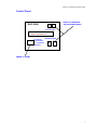
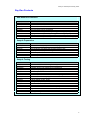
1
POLYTEST
Product User Manual
Autocycle Test Sample
Notching Cutter
Copyright (C) 1999 all rights reserved World Wide
Revised Feb 2003 issue 1
RAY-RAN TEST EQUIPMENT LTD
Kelsey Close • Attleborough Fields Industrial Estate
Nuneaton • Warwickshire • CV11 6RS • United Kingdom
Tel : +44 (0)24 7634 2002 • Fax : +44 (0)24 7664 1670
E-Mail : [email protected]
Web Site : http://www.ray-ran.com
www.ray-ran.com
POLYMER TEST EQUIPMENT FOR WORLD WIDE QUALITY
CONTROL
Autocycle Test Sample Notching Cutter
Contents
User Manual ..................................................................................................................................3
Description of the Apparatus......................................................................................................3
Lifting and Installation .................................................................................................................3
Shipping Characteristics.............................................................................................................3
Electrical Characteristics ............................................................................................................3
Safety Switch ................................................................................................................................4
Test Samples ................................................................................................................................4
Loading the Test Samples...........................................................................................................4
Setting the Cutter Height and Checking the Notch Depth .......................................................4
Cutting Feeds and Speeds ..........................................................................................................5
Removing the Cutter Wheel ........................................................................................................6
Cleaning the Apparatus...............................................................................................................6
Maintenance..................................................................................................................................6
Control Panel ................................................................................................................................7
Ray-Ran Products and Services.................................................................................................8
2
Autocycle Test Sample Notching Cutter
User Manual
Please read this manual before installing and operating the apparatus. The enclosed
information will enable you to become familiar with the equipment, ensure it is installed properly
and used correctly in order to give trouble free service.
If you have any questions about the installation and function of the apparatus, please contact
Ray-Ran, who will be pleased to assist you.
Description of The Apparatus
The Notching Cutter has been designed to machine very accurate notch profiles into polymer
test sample materials, such as Izod and Charpy specimens.
The apparatus is capable of producing notch profiles to all International test standards, such as
ASTM and ISO. The cutters are made from tungsten carbide which is an extremely hard and
durable material. The cutting edges are optically profile ground to very close tolerances.
Different cutter profiles are available to suit standard and special notch requirements.
Once the test samples have been clamped into the vice, the cutting cycle is carried out
automatically. After the notches have been machined, the cutter stops rotating before the test
samples are traversed back to the start / unloading position.
The notch size (distance under the notch) is checked using a comparitor which forms an integral
part of the front console. Setting blocks are supplied to set the comparitor.
Lifting and Installation
The apparatus can easily be lifted by two people, each holding one end of the cabinet. Position
the hands under the base and in between the mounting feet to prevent them becoming trapped
when the apparatus is lowered down onto the mounting surface.
The apparatus should be placed and levelled by adjusting the mounting feet on the surface of a
sturdy flat bench or table. If any vibration is allowed to generate between the apparatus and the
mounting surface, it could effect the surface finish of the notch profile.
Ensure that a single phase electrical power supply is readily available.
Shipping Characteristics
WEIGHT
NET
GROSS
26 kg
39 kg
LENGTH
56 cm
SIZE
WIDTH
HEIGHT
38 cm
25 cm
Electrical Characteristics
220-240 volts AC 1 ph 50 Hz
110-120 volts AC 1 ph 60 Hz
Please check the name plate to confirm the correct electrical supply. The power supply inlet
socket is fitted with a 5 amp fuse. The rectifier is fitted with a 1 amp fuse.
3
Autocycle Test Sample Notching Cutter
Test Samples
The test samples should be prepared in accordance with the test standards being worked to.
The shape of the test sample can have a significant influence in the way the test sample is held
and subsequently machined. For example, if the test sample has been moulded and the side
faces are produced with a large draw angle, then it may prove extremely difficult, if not
impossible, to find a true reference face from which the depth of the notch can be machined and
measured. The taper effect tends to tilt the test sample away from the vertical axis. One sample
could tilt one way and another the opposite way, but in any event, both will give an incorrect and
variable vertical measurement on the dial comparitor. This inconsistency is often incorrectly
mistaken as a machining fault, suggesting wear in the bearings and slideway of the apparatus.
Therefore, special attention should be paid to the parallelism of the side faces of the test sample
in order to avoid such problems. If, however, tapered side faces are unavoidable, try and ensure
the test samples are always referenced to the same faces when they are machined and
inspected. By gently rocking the test sample on the comparator, it should be possible to record
the maximum height as the datum.
It is worth mentioning that the physical tests to be carried out on the test samples should also
take into account any taper that is present. For example, in both Izod and Charpy tests, the
impact energy is expressed as a unit of the cross sectional area of the test sample, and
therefore the mean dimensions should be used to give the true cross section.
Safety Switch
The front transparent hinged guard, which when lifted gives access to the cutter and vice, is
fitted with a safety switch which disconnects the electrical power supply to the drive motors
when the guard is raised. Therefore, whilst the test samples are being loaded into the vice, or
any height adjustments are made, the apparatus can not be inadvertently turned on.
IMPORTANT
If the micro switch operated by the guard fails, the apparatus must not be used until an
effective repair has been carried out.
Loading the Test Samples
The vice which clamps the test samples incorporates an adjustable guide rail to site and
position the test samples centrally about the vice and hence the cutter.
To adjust the position of the guide rail, first undo the outer locking thumb wheel. Use the central
thumb wheel to set the guide rail at a distance equal to half the test sample length from the
centre of the vice. Keeping a light pressure on the central thumb wheel, tighten the outer locking
thumb wheel. The test samples can now be placed and secured in the vice.
Setting the Cutter Height and Checking the Notch Depth
The apparatus has two height references to set or adjust the cutter height in order to produce
the correct notch depth, as follows.
Initially, cutter height is set using the vertical scale adjacent to the cutter. This scale denotes the
height under the notch. The cutter height is adjusted as follows.
Release the two clamping screws either side of the cutter housing. Rotate the thumb screw on
top of the cutter housing to raise or lower the cutter as required. Set the arrow to read the
distance equal to the remaining width under the notch after the notch has been machined, for
example, a Charpy test sample according to the ISO standard should be 10 mm wide and
4
Autocycle Test Sample Notching Cutter
measure 8 mm under the notch. Lock up the two clamping screws, and then load just one test
sample into the vice and machine a notch.
Using the correct setting block (supplied) which is equal to the height of the sample measured
under the notch (8mm for ISO and 10.16mm for ASTM), set the dial comparator on the left hand
side of the apparatus to read zero. Place the notched test sample under the dial comparator
with the notch located on the “V” rest and with the test sample perpendicular to it. Note if there
is any variation in size from the zero datum. If there is any difference, undo the clamping screws
again and adjust the cutter up or down by the amount of variation observed. Use the dial
indicator engraved on the top of the thumb wheel to gauge the fine adjustment required. Note,
one division of the dial on top of the thumb screw is equal to 0.1 mm vertical movement of the
cutter.
If need be, repeat this procedure until the correct size of notch is obtained.
IMPORTANT
Please note that the tip geometry of the cutter is not the same as the notch profile that
the cutter actually produces. This is because the cutter, in order to cut effectively,
requires radial relief and clearance angles. Therefore, measured statically, the tip
geometry is different to when it is rotating, namely because the tip describes a projected
or swept profile.
Cutting Feeds and Speeds
Selecting the correct traverse feed rate and cutting speed is a matter of trail and error.
However, it is suggested that for a new material, the cutter speed is set at 1,000 rpm and the
traverse speed set at 0.1mm/rev. Fortunately, most polymer materials are not too sensitive to
the machining parameters, and therefore it is a relatively simple and quick matter to find a
suitable set up that will produce a good notch finish.
The control panel shown on page 7 explains how the machining parameters are set and
adjusted.
Some polymer materials, and especially very soft ones, may produce a folding swarf still
attached to the test sample where the cutter has broken out from the back face of the sample.
Although it can often be minimised by altering the feed and speed, it may not be possible to
eliminate this problem altogether. Generally, when this swarf is removed (by hand) after the
sample has been removed from the vice, it is usually found that the notch profile is still
acceptable. However, if this swarf presents a serious problem, then machine more than one
sample at a time and discard the last sample.
The combination of cutting speeds and traverse feeds available are shown in the table below.
CUTTER SPEED
MAX
2000 rpm
1800 rpm
1600 rpm
1400 rpm
1200 rpm
1000 rpm
800 rpm
600 rpm
400 rpm
0.47 (mm/rpm)
0.51 (mm/rpm)
0.58 (mm/rpm)
0.66 (mm/rpm)
0.78 (mm/rpm)
0.94 (mm/rpm)
** 1.15 (mm/rpm)
TRAVERSE SPEED
MEAN
0.27 (mm/rpm)
0.29 (mm/rpm)
0.34 (mm/rpm)
0.39 (mm/rpm)
0.46 (mm/rpm)
0.55 (mm/rpm)
0.70 (mm/rpm)
** 0.93 (mm/rpm)
MIN
0.08 (mm/rpm)
0.09 (mm/rpm)
0.10 (mm/rpm)
0.12 (mm/rpm)
0.14 (mm/rpm)
0.15 (mm/rpm)
0.20 (mm/rpm)
0.26 (mm/rpm)
0.40 (mm/rpm)
** Recommended limiting values.
5
Autocycle Test Sample Notching Cutter
The traverse speed can be displayed in metric or imperial units. By simultaneously holding the +
and - keys together, the units will alter from the previous setting.
To start machining a new material, it is suggested that the cutter is set to 1,000 rpm and the
traverse at 0.1 mm/rev. and then adjusted as required.
The feed and speed control microchip will automatically store the last settings that were used
and will reference the apparatus to these settings when the apparatus is switched on again.
Removing the Cutter Wheel
Position a spanner on the two flats of the retaining washer adjacent to, and outboard of, the
cutter to hold the spindle stationary. Insert the Allen key into the clamping screw in the centre of
the spindle and undo it. Remove the end cap and retaining washer. The cutter can now be
withdrawn from the spindle.
IMPORTANT
Avoid contact with the tip of the cutter.
Cleaning the Apparatus
The tray positioned in the base of the apparatus will collect most of the swarf. However,
depending on the frequency of use, occasionally use a fine paint brush to clean around the
components.
Maintenance
All of the bearings are sealed for life, and therefore do not require lubricating.
The slide way carrier runs on special plastic bearing strips, which again do not require any form
of lubrication. However, after several hundred hours of operation, if any variation is experienced
with the notch profile, check that there is no noticeable play between the slide carrier and
slideway. If there is, adjust the slide way by tightening up the adjustment screws projecting from
the end of the carriage which are exposed by removing the black plastic protection caps. First,
disconnect the electrical power supply. Remove the left hand side cover plate and slide the
pulley belt off the pulley so that lead screw which moves the carrier can be turned by hand.
When taking up any clearance between the carrier and the slideway, be careful not to create an
interference. To check the fit, rotate the lead screw and ensure there is no undue resistance.
Reposition the pulley belt and side cover.
6
Autocycle Test Sample Notching Cutter
Control Panel
PRESS TO INCREASE
RAY-RAN
+
-
OR DECREASE SPEED
CUTTER SPEED
CUTTER SPEED DISPLAY - RPM
TRAVERSE SPEED DISPLAY
TRAVERSE SPEED
START
TO CHANGE
UNITS PRESS
+ - TOGETHER
+
-
AND HOLD
PRESS TO START
7
Autocycle Test Sample Notching Cutter
Ray-Ran Products
Raw Material Evaluation
Code
RR/5MBA
RR/5SA
RR/5MPCA
RR/DGA
RR/BDA
RR/ADV
RR/VOY
RR/DIS
RR/MB
Product
Model 5MBA Melt Flow Indexer
Model 5SA Melt Flow Indexer
Model 5MPCA Melt Flow Indexer
3 Column Density Gradient Apparatus
Apparent Bulk Density Apparatus
Adventurer Balance (Readability 0.1mg) 110/260g Capacity
Voyager Balance (Readability 0.1mg) 62/410/100g Capacity
Discovery Balance (Readability 0.1mg) 110/310g Capacity
Moisture Balance (Readability 0.1%, 0.05%, 0.01%) 110/35/45g Cap
Sample Preparation
Code
RR/TSMP2
RR/HCP
RR/PCP
RR/NC
RR/CNC
RR/CNC 2
TSC + Standard
Product
Model 2 Test Sample Injection Moulding Apparatus
Hand Operated Test Sample Cutting Press
Pneumatically Operated Test Sample Cutting Press
Auto Cycle Test sample Notching Cutter
Test Sample Profile Cutter
Test Sample Profile Cutter - Larger
Test Sample Cutters
Sample Testing
Code
RR/HDV2
RR/HDV4
RR/HDV6
RR/TAA
RR/LTB
RR/ESC
RR/FSL
RR/FSHP
RR/IMT
RR/FWT
RR/FD
RR/ETT
RR/FT
RR/M
D202
B202
WS777
Product
2 Station HDT/Vicat Softening Point Apparatus
4 Station HDT/Vicat Softening Point Apparatus
6 Station HDT/Vicat Softening Point Apparatus
Thermal Ageing Apparatus
Low Temperature Brittleness Tester
Environmental Stress Cracking Apparatus
Unrestrained Linear Thermal Film Shrinkage Apparatus
Hot Plate Film Shrinkage Apparatus
Universal Pendulum Impact Tester
Falling Weight Impact Tester
Falling Dart Impact Tester
Advanced Elmendorf Tear Tester
Static And Dynamic Friction Tester
Universal Tensile Tester – Various Capacity
Digital Handheld Durometer
Analogue Handheld Durometer
Analogue & Digital Durometer Workstations
8