1
Chapter 4: Setup
MLS300 Series User’s Guide
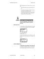
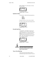
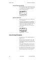
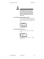
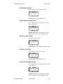
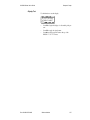
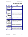
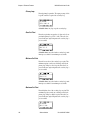
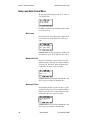
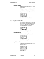
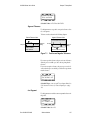
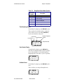
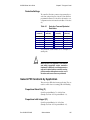
Reversed Thermocouple Detection
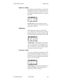
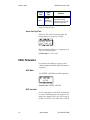
This selection enables polarity checking for thermocouples. If
a reversed thermocouple alarm occurs, the controller sets the
loop to Manual control at the SENSOR FAIL OUTPUT
power level and displays the alarm.
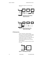
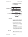
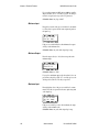
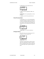
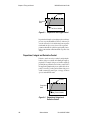
01 REVERSED T/C
DETECT ?
OFF
ALARM
Selectable Range: ON or OFF.
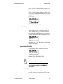
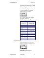
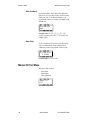
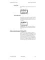
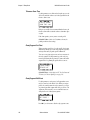
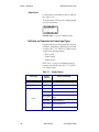
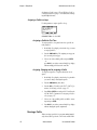
Input Pulse Sample Time
This parameter is only available for Loop 17 on MLS316 and
Loop 33 on the MLS332.
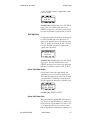
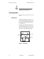
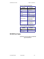
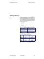
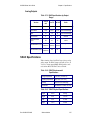
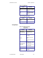
You can connect a digital pulse signal of up to 2 kHz to the
controller's pulse input. In this menu, you specify the pulse
sample period. Every sample period, the number of pulses the
controller receives is divided by the sample time. The
controller scales this number and uses it as the pulse loop's
process variable.
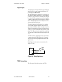
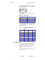
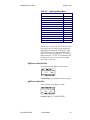
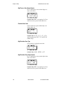
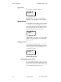
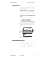
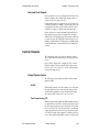
17 INPUT PULSE
SAMPLE TIME ? 1S
ALARM
Selectable Range: 1 to 20 seconds.
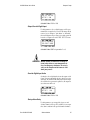
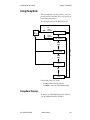
Linear Scaling Parameters
The following screens are only available if the input type is
LINEAR or PULSE.
The linear scaling screens appear under the SETUP LOOP
INPUTS menu. They let you scale the “raw” input readings
(readings in millivolts or Hertz) to the engineering units of the
process variable.
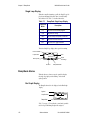
For linear inputs, the input reading is in percent (0 to 100%)
representing the 0 to 60 mV input range of the controller. For
pulse inputs, the input reading is in Hertz (cycles per second.)
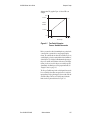
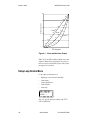
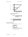
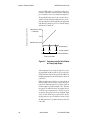
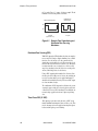
The scaling function is defined by two points on a conversion
line. This line relates the Process Variable to the input signal.
The engineering units of the process variable can be any
106
Watlow Anafaze
Doc.# 0600-3070-2000