1
HARDING UNIVERSITY
Final Design Review
Andrew Combs
Emilia Faraj
Ethan Lilly
Jeff Wood
March 2, 2012
Page 1
Table of Contents
Project Overview and Status ......................................................................................................................... 4
Pill Storage and Dispensing Mechanism .................................................................................................. 5
Device Housing........................................................................................................................................ 22
Power Supply .......................................................................................................................................... 33
Control System ........................................................................................................................................ 39
User Interface System ............................................................................................................................. 53
Project Plan ................................................................................................................................................. 62
Organization and Management ............................................................................................................... 63
Gantt Chart: Spring 2012 ........................................................................................................................ 64
Pert Chart: Spring 2012 ........................................................................................................................... 65
New Gantt Chart ..................................................................................................................................... 66
Budget ..................................................................................................................................................... 67
References ............................................................................................................................................... 71
Appendices.................................................................................................................................................. 73
Microprocessor ....................................................................................................................................... 74
Wi-Fi Transceiver Module ...................................................................................................................... 83
LCD Screen............................................................................................................................................. 92
Keypad .................................................................................................................................................... 98
RFID Reader ......................................................................................................................................... 108
Alarm .................................................................................................................................................... 115
Force Sensors ........................................................................................................................................ 118
Motor .................................................................................................................................................... 123
Real Time Clock ................................................................................................................................... 125
Power Supply ........................................................................................................................................ 130
Page 2
Requirements Specification ...................................................................................................................... 137
Overview ............................................................................................................................................... 138
Problem Statement ................................................................................................................................ 139
Customer Needs .................................................................................................................................... 139
Operational Description ........................................................................................................................ 140
Technical Requirements........................................................................................................................ 141
Deliverables .......................................................................................................................................... 143
Testing Plan .......................................................................................................................................... 143
Page 3
Project Overview and
Status
Page 4
Pill Storage and Dispensing Mechanism
It was clear from the construction of previous prototypes during the fall that proper
connection between all of the mechanical components would be a major issue. One of the most
important mechanical connections is that between the pill storage bin and the auger-casing
mechanism. Previously, the pill storage bin and the auger-casing mechanism were designed as
separate units. This design is shown in Figures 1 and 2. This is a suboptimal design because this
design requires the extra work of accurately attaching each pair of these components. A
preferable design is shown in Figure 3. In this design, the pill storage bin and the auger-casing
mechanism are designed as one seamless unit. This assures that there are no obstruction to the
flow of pills between the pill storage bin and the auger casing mechanism.
Figure 1. Previous Pill Storage Bin Design
Page 5
Figure 2. Previous Casing Design
Figure 3. Combined Bin and Casing
Page 6
To test the design of the pill storage and dispensing mechanism, a new prototype was
constructed. A new feature of this prototype that differentiates it from previous ones is that this
included a design to synthesize the pill storage and dispensing mechanism with the device
housing. The design of the prototype is shown in Figures 4 and 5. The T shown on the back of
the bin is the means by which the bin attaches to the rest of the device. This T is designed to slide
into bin holders on the device wall. A drawing showing one of these bin holders is shown in
Figure 6. In most other respects, this design was the same as previous versions.
Figure 4. Back view of the prototype Design
Figure 5. Top view of the prototype design.
Page 7
Figure 6. Design of the bin holder
The main purpose of this design is the convenience to the user. The user will be able to easily
remove pill storage and retrieval units from the device housing. This allows for easy loading of
pills, easy washing of the mechanisms, and customization of the types of mechanisms the user
can put into the device. A figure of the design of the prototype is shown in Figure 7. A goal of
this prototype was to build a bin slot and motor mount which would guarantee an accurate mate
between the auger gear and the motor gear. To achieve an accurate mate between the two gears,
two things need to be true. First, the axis of the motor shaft and the axis of the auger must be
parallel. The angle of the auger shaft is 45⁰ from the horizontal. This means that the motor mount
needed to hold the motor at a 45⁰ angle. Second, the distance between the two gears must be a
certain value. This distance is determined by the diameters of the two gears. If this distance is too
small, then the design will be impossible because the gears will be taking up too much space. If
this distance is too large, then the gears will not mate with each other because they will be
separated. The goal was to have two-thirds of the gear teeth overlap with each other.
Page 8
Figure 7. Design of the prototype.
The pill storage bin, the auger, and the two gears were 3d printed. The bin holder and the
motor mount were built out of Plexiglas. A picture of the prototype is shown in Figure 8. A
closer picture of the bin holder is shown in Figure 9. The lessons learned from this prototype
revealed the need for several more changes to the design.
Page 9
Figure 8. Prototype Build
Page 10
Figure 9. Bin holder for the prototype
The prototype ran successfully with all of the pills shown in Figure 10. Two tests were
done for each pill. In each test, approximately twenty pills were placed into the device. All of the
pills were then dispensed from the device. In every case, the device dispensed one pill at a time
and no jamming occurred. The one exception to this is that there was one minor malfunction
with the purple pills on the far right in the photograph. These pills bridged in the device across
the slope that connects the pill storage bin to the auger-casing mechanism. This slope is labeled
in Figure 11. A photograph of the bridging effect is shown in Figure 12. This bridging only
occurred once and was addressed with design changes described later in the report.
Figure 10. Pills successfully dispensed by the device
Page 11
Figure 11. Slope between the bin and the casing.
Figure 12. Picture of the Pill Bridging
Page 12
There was one type of pill that was not successfully dispensed by the device. This pill is
shown in Figure 13. This pill type caused the device to jam. This pill type is unique because it is
a disc with a diameter smaller than the disc shaped pill that was successfully dispensed by the
device. The dynamics are slightly different for disc shaped pills than for capsular pills because in
capsular pills the small dimension is biaxial while in the disc shaped pills the small dimension is
uniaxial. There are some design changes to the auger that are intended to alleviate the problem
that these disc shaped pills encountered. These changes are described later in this section of the
report.
Figure 13. Pill unsuccessfully dispensed by the device.
Even though this prototype ran successfully, the mate between the auger gear and the
motor gear was not sufficiently accurate. The motor shaft and auger shaft were misaligned.
Figure 14 shows this misalignment. The motor gear would drive the auger gear with some
interference. It was clear that a new method was needed to integrate the bin into the device. It
was decided that the best method would be to print the bin holders and motor mounts using the
3d printer. Parts made using the 3d printer are much more accurate that those made by cutting
Plexiglas with a band saw. The design for the new bin holder is shown in Figure 15. This part
will be attached to the device wall using mechanical fasteners. The bolts will go through the
holes in the part. Using mechanical fasteners is more accurate than gluing because parts that are
in the process of being glued together are susceptible to slipping while the glue is drying. The
holes can be drilled into the device wall very accurately using the milling machine that is located
in the machine shop in the Harding University Ulrey building. This machine has a digital readout
specifying the position of the tool head, allowing for very accurate positioning of the tool head
position. This means that the holes can be drilled at where they need to be within acceptable
tolerance.
Figure 14. Misalignment between auger gear and motor gear.
Page 13
Figure 15. Design of the bin holder.
A similar design process was carried out for the motor mount. The motor mount will be 3d
printed to ensure high accuracy. A picture of this design is shown in Figure 16.
Figure 16. Design of the Motor Mount
The full integration of all of these components with the device housing is shown in
Figure 17. This figure is not a drawing of the overall device. It only shows how the dispensing
mechanism, the motors, and the device housing integrate together. The holes in the device
Page 14
housing are designed to match exactly with the holes in the bin holder and the motor mount.
Bolts pass through these holes to connect these parts to the device housing. An up close view is
shown in Figure 18. Everything is positioned exactly to ensure that two thirds of the teeth
overlap in the mating auger and motor gears. Figures 19 shows the layout of holes in one side of
the device housing. This will serve as the template for drilling the holes with the milling
machine.
Figure 17. Integration of the dispensing mechanism, motor, and device housing.
Figure 18. Up-close view of the integration.
Page 15
Figure 19. Template for drilling holes in the device wall.
Some changes were made in the design of the auger-casing mechanism. First the minor
diameter of the auger was increased from 0.64 cm to 1.27 cm (0.25 in. to 0.5 in). This new auger
is shown in Figure 20. This design change should assist with the dispensing of pills that are very
long. A prototype that was 3d printed during the fall semester had trouble dispensing pills with a
length of approximately 1 in. This was due to problems rotating a long, flat pill with a curved
surface. A larger minor diameter means that the surface of the auger will be less curved relative
to the pill.
Figure 20. Auger with increased minor diameter.
The second change was done to the casing and is shown in Figure 21 and Figure 22.
Additional support was added to the end of the casing. The purpose of this support is to limit
movement of the auger. Previously the end of the auger was free to rock upward. This rocking is
undesirable due to the risk of pills wedging underneath the auger. A picture of this phenomenon
is shown in Figure 23. With this new support that movement will be constrained.
Page 16
Figure 21. Illustration of the added support at the end of the casing.
Figure 22. Illustration of the added support with the auger.
Page 17
Figure 23. Pills jammed underneath the auger.
The last change was that the slope connecting the bin to the casing was increased. This is
illustrated in Figure 24. This change should alleviate the bridging problem encountered during
the testing of the prototype. The angle of this slope in the prototype was 60°, which is less than
the 70° in the new prototype. The only other way to alleviate this problem would be to shrink
the dimensions of the pill storage bin or increase the diameter of the casing. Since these values
are already locked by other design considerations, the problem must be solved by increasing the
slope of the connection
Figure 24. Illustration of the connection between the casing and the bin.
Page 18
A pill storage and dispensing mechanism intended for larger pills that implemented these
design changes was 3d printed and connected to the device housing. A picture of this mechanism
is shown in Figure 25.
Figure 25. Pill storage and dispensing mechanism connected to the device housing.
This device performed successfully with both of the pills shown in Figure 26. The device
dispensed both of these pills one at a time in all tests with no instances of jamming. This device
is also successful in achieving an improved mate between the auger gear and motor gear. The
device ran much more smoothly and quietly than the previous prototype. This is due to the fact
that the auger shaft and motor shaft are parallel, and the distance between the two gears is
correct. This allows for an accurate mate between the two gears. A picture of this phenomenon is
shown in Figure 27. The only critical flaw in the device is that it sits too high in the device
housing. The lid of the device housing cannot shut properly. For this pill storage and dispensing
mechanism this will be alleviated by cutting off some of the top of the bin. All future models will
be designed to sit lower in the device.
Page 19
Figure 26. Pills successfully dispensed by the device.
Figure 27. Successful mating of the gears.
A few more additional design changes were made after the completion of the second pill
storage and dispensing mechanism. First more measures were taken to alleviate the problem of
pill bridging that was discussed earlier. These changes are displayed in Figure 28.
Page 20
Figure 28. New Measures to Prevent Bridging
The connection angle was increased again to 80⁰. The main problem with increasing this
connection angle in previous designs is that it would result in increasing the size of the back of
the casing. Increasing the size of the back of the casing would result in pills resting on the back
of the casing. This problem is shown in Figure 29. This problem can be solved by lowering the
point where the back of the casing changes being from angled to vertical.
Figure 29. The flaw in previous connection designs
Page 21
A new auger casing mechanism was designed to alleviate the bridging problem discussed
previously. This design is shown in Figure 30. This design works by greatly decreasing the
distance between the minor and major diameters. This means that none of the pills will try to
rotate with the auger. Instead, they will ride on top of the auger shaft. This is the phenomenon
that caused the larger disc shaped pills to be successfully dispensed by the first prototype and is
shown in Figure 31.
Figure 30. Auger design to prevent jamming in disc shaped pills.
Figure 31. Pills riding on top of the auger shaft.
This design will be tested to see if it works with capsular pills. If it does, then all of the
smaller pill storage and dispensing mechanisms will switch to this design. If not, then three
different types of pill storage and dispensing mechanisms will need to implemented in the final
build.
Page 22
Device Housing
Due to the difficulty with cutting straight edges on bulky pieces of Plexiglas with a band
saw, it was deemed necessary to have the Plexiglas cut by a glass cutting company. It only cost
ten dollars to cut the six panels that make up the device housing. Holes were drilled in each of
the six panels using a mill as a drill press so that metal bracings and bolts could be used to fasten
the panels as illustrated in Figure 31. The bracings were strategically placed so that they would
not interfere with the placement of the dispensing mechanisms, while maintaining their function
of adding structural strength.
Figure 31: Isometric Image of Device and Dimensions.
The designed placement of the LCD screen and keypad were changed to the front of the
device housing because it was tested to be convenient on a counter top much like a microwave.
Also, it is preferable to attach electrical components to a stationary part. Both the keypad and the
LCD screen will have wires attached to them. These wires would get in the way of the user when
they raise the lid. The lid can be seen in both Figure 32.
Page 23
Figure 32: Hinged Lid Partially Opened.
Construction of Pill Retrieval Door:
Figure 33 shows the initial design of the pill retrieval door from last semester. The initial
design used two smooth surfaced horizontal tracks that constrained the door on top and bottom,
and motion was to occur in the form of sliding along the tracks. Dr. Miller pointed out that this
design of the pill retrieval door would likely cause the door to bind due to the friction along the
two tracks. Instead of redesigning the entire subsystem, the issue was resolved by adding wheels
to the door to reduce friction. This solution saved time in our schedule because time was not
wasted completely redesigning the door. Also, it saved money in our budget because the eight
wheels were obtained from two small toy cars.
Page 24
Figure 33: Initial Design of Automated Pill Retrieval Door and Rack and Pinion System
Construction of the pill retrieval door began by cutting the 10.16 cm x 10.16 cm (4 in x 4
in) doorway out of the front panel of the device housing as shown in Figure 34. The doorway
was cut using a standard mill, and was a slow process because the Plexiglas cracked quickly
when the mill’s feed rate was too rapid. It ultimately took two passes to cut completely through
the 0.3175 cm (1/8 in) thick Plexiglas. The door itself was cut using the same process as the
doorway.
Page 25
Figure 34: Pill Retrieval Door from a Front View of the Device (Motor Not Shown).
Thin strips of Plexiglas were cut with the band saw in order to construct the two tracks.
The strips were glued together in an “L” shaped fashion, and these two “L” shaped tracks were
glued directly to the device as shown in Figure 35.
Page 26
Figure 35: Pill Retrieval Door from a View Inside of the Device (Motor Not Shown).
The eight wheels in Figure 35 were connected to the door in four pairs by metal axles.
Four small holes were drilled through the door, where each axle was inserted. The wheels are
completely fixed to the axle, and door motion occurs through rotation of the axle within the door.
The stepper motor was bolted to the wall by a motor mount shown in Figure 36, and will
be completely constrained. The motor mount was constructed from thin strips of Plexiglas and
small metal braces being glued together. The pinion is fixed to the motors shaft and only has
rotational freedom.
Page 27
Figure 36: Pinion, Stepper Motor, and Motor Mount.
Design Change of the Pill Retrieval Area:
Through testing it was discovered that the force sensors were negatively affected by noise
in the form of vibrations. The prototype would fail by mistaking noise for a pill dropping into the
pill retrieval area. This failure only occurred when these vibrations were created by violently
banging on the table the force sensors were resting on, and this form of vibrational noise was
deemed to be worst case scenario. The solution to the problem was to suspend the pill retrieval
area from the base of the device housing using string. The string is attached to a hole at each
corner of the pill retrieval area, and acts as a damper by dampening much of the vibrations
transferring from the device housing to the pill retrieval area. The string is fishing string
specifically because it is strong, light weight, and cheap. There is potential that this problem
could have been solved with digital filtering; however, the force sensors are not good at
measuring the actual force placed on the sensor. They are only good at detecting spikes in force.
This makes it difficult to distinguish between noise of a certain magnitude and the dropping of a
pill. This mechanical filtering method is an easy, foolproof way of solving the problem.
Page 28
Figure 37: Pill Retrieval Area with Preloaded Force Sensor
The four holes that will suspend the pill retrieval area are shown in Figure 37, and
correspond to the four holes at the top of the “U” shaped supports in Figure 38. The preloading
plate and bolts provide the necessary preload for the force sensor to detect pills dropping into the
tray. All of the panels that compose the pill retrieval area are Plexiglas, and were cut using a
mill. The pill retrieval area is glued together in accordance with the dimensions shown in Figure
39. The final design of the pill retrieval area has been constructed and integrated into the device
displayed in Figure 40, and it operated successfully in tests where worst case scenario vibrations
where created within the device.
Page 29
Figure 38. U shaped supports.
Figure 39: Dimensions of Pill Retrieval Area
Page 30
Figure 40: Pill Retrieval Tray Suspended within the Device
Slide:
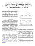
Construction of the slide is underway. The colored portions of the slide in Figure 41 have
been milled out of Plexiglas. The final dimensions of the slide’s width and height will be known
when the dispensing mechanisms are finalized, so slide construction is currently halted until
these values are known. The slide itself will consist completely of Plexiglas, and will be glued
together to form its shape. The support structure of the slide will consist of Plexiglas and metal
braces, and is not shown. Construction of the support structure is also in progress.
Page 31
Figure 41: Slide Design and Current Progress
Page 32
Power Supply
Overview
The purpose of the power supply is to receive power from the wall outlet to power the
device. It will convert the voltage from AC to a lower DC voltage to supply the power needed
for the electrical components. One of the requirements stated previously is that the power supply
should have back up batteries that will keep the device running for at least one week.
Initial Design
The initial design for the power supply was to gather the components-the transformer,
resistors, capacitors, regulators and build it. It had been simulated to work in Multisim to power
all of the subsystems as necessary, but due to heavier components than anticipated, a power
supply was purchased to meet the device’s weight requirements.
New Design and Progress
The power supply purchased regulates voltage to use 12 V at 0 to 0.5A, 5 V at 0 to 2A, and
3.3 V at 0.5 to 4A to power the different components the device needs to operate. Note that the
motors are now operating at 12V as opposed to 15V in the initial design; there is also only one
sensor being used, and an additional motor for the door gate. See Appendix J. These components
are the following:
10 Stepper Motors: 12 VDC at 300 mA
Alarm: 5V at 250mA
Microprocessor: 5V at 29-45 mA
Keypad: 5 V at 5 mA
LCD Screen: 5V at 300mA
1 Force Sensor: 5V at 4.5-80mA
Wi-Fi Transceiver Module: 3.3V at 150mA
RFID chip: 5V at 100mA
Power calculations had to be recalculated for each component to make sure the power
supply can supply enough power to all of the components.
For the 12V:
Page 33
For the 5V:
For the 3.3V:
The total power needed for the device to function at its worst case (motors being used at
12V) is 40.38 W. The power supply can give up to 55 W which is more than what is needed.
Construction and testing
The construction still needed for the power supply is to solder wires that will go to the
wall outlet and from each voltage output to the subsystems. Each subsystem was tested before
being integrated to the power supply.
Figure 42. DC Voltage Outputs from Power Supply
Page 34
The DC voltage outputs from the power supply shown in Figure 42 are very steady as
time elapsed. For the 3.3V, a voltage average of 3.738V was measured, for the 5V, a voltage
average of 5.469V was measured, and for the 12V, a voltage average of 12.60V was measured.
The power supply was tested individually with each subsystem and with several subsystems at
the same time, powering all of them successfully.
Figurer 43. Power Supply with Subsystems
Figure 43 shows the power supply connected to some of the subsystems, the RFID
reader, the LCD screen, the microprocessor, the alarm, and the real time clock when they were
integrated to test their functions. Other subsystems that were integrated and not shown in the
picture were the motor controller circuit, the sensor in the pill retrieval area, and the keypad.
Battery Backup Design and Progress
One of the requirements for the battery is that the device should work for at least one
week with a backup power system. The power calculations can then be multiplied for the device
dispensing nine pills, three times a day, for an entire week. Another requirement related to the
battery is the device’s weight.
Page 35
Initial Design
The initial design of the battery was to have four 9V disposable alkaline batteries with
two parallel pairs connected in series, supplying power after a power outage. Power from the
batteries was at 18V so the motors could run with 15V.
New Design Construction and Testing
Since the motors are still the components that require the most power, 36 W, running at
12 V, we do not need 18V to power the motors. Data was taken to show the relationship between
voltage and torque. When the motors are using 9V, it is still a good torque and the motors
function well. Therefore, when the device is battery powered, the motors will be running at 9V.
This means there will only be two 9V batteries in parallel that still supply all of the power
needed.
Figure 44. Batteries’ Schematic
Figure 44 shows the battery schematic in Multisim. Figure 45 shows the batteries’ circuit
schematic with the components and the output for each regulator, 5V and 3.3V. They both show
a steady signal through time.
Page 36
Figure 45. Batteries Circuit Output Voltages
Again, power calculations were recalculated for the battery powered components. The
components are taken into account to operate at their maximum – nine pills for seven days for
three times a day. The components that most need power during this time are:
Alarm:
Sensor:
Motors:
RFID:
Page 37
Battery Indicator
Initial Design
The initial design for the battery indicator was to have the microprocessor read the
voltages of the batteries and indicate if the batteries were low. Since the batteries will only be
used in case of a power outage, the batteries could be drained by just checking if there is enough
voltage without being used.
New Design
The battery indicator circuit will be attached to the battery circuit in the power supply
circuit with a switch that if it is turned on and there is enough voltage to operate, an LED will
turn on; similarly, if the switch is on and there is not enough voltage, no LED will turn on. The
voltage considered high enough for the LED to turn on is 7.7V or higher.
Figure 46 shows this scenario of having the switch off on the left side, and the switch on
with the LED on, on the right side.
Figure 46. Battery indicator circuit with the switch off and on
Page 38
Control System
Overview:
The overall purpose of this system is to control all of the other components of the device
using electrical signals so that the device operates according to the specified requirements. More
specifically, this system makes sure that the pills are dispensed when they are supposed to be,
that the right amount of pills are dispensed, that the patient receives the pills, and that the
caretaker is informed if anything is wrong. This system communicates with most of the other
systems to achieve this. All of the information about the medication in the device; such as how
many pills there are in each bin, when each pill should be dispensed and how many of each pill
should be dispensed, is all stored in the control system.
Microprocessor:
Currently the processor has been put onto a breadboard using a 64 pin socket that has
been soldered onto a PCB with a header for each pin. Programming has been done using ICSP
(In Circuit Serial Programming) using the MP Lab equipment.
Figure 47: This shows the socket with the breadboard and a few components
connected.
Page 39
Currently all of the programming done has been for each component individually. The
keypad has been programmed to output to the LCD as required. A program has also been written
to receive data from the RFID reader using the UART module built into the processor. Once a
card is scanned the processor outputs a confirmation message to the LCD screen. A program has
been written for the most recent prototype that will turn a single motor and poll the A/D reading
from the sensor until a pill drop is detected. The motor controller circuit has also been tested and
a program has been written that can successfully turn multiple motors, one at a time, and in
different directions. The functionality of setting the time and getting the time for the real-time
clock has been programmed, also the programming required to turn on and off the alarm has
been finished. The Wi-Fi transceiver is the only component that the programming is not finished
for. Once this is done, the final system program can be completed.
The processor will first be soldered to a SchmartBoard and then connected to a
professional PCB. A picture of the SchmartBoard can be seen below. The PCB is designed to
have through holes that match the outer holes on the SchmartBoard. Double sided male
connectors will be used to attach the two boards.
Figure 48: This is a picture of the SchmartBoard that the processor will be soldered to
The following design includes connections for everything that will be interfaced with the
microprocessor. It also contains the circuitry for the motor controller, the keypad, the alarm, and
the LCD screen. The orange box shows the outline of where the SchmartBoard will be
connected. This design is 10.2 x 10.2 cm (4 x 4 inches). This board has been ordered from
www.4pcb.com.
Page 40
Figure 49: This shows the initial design for the control subsystem done in ultiboard
Page 41
Wi-Fi Transceiver Module:
This module has taken some time to prepare for testing. It does not have pins that allow it
to be inserted directly into a breadboard so a separate circuit board was required to be designed
and printed. Here is the first design that was made in ultiboard:
Figure 50: A PCB design for the Wi-Fi Transceiver.
The component has finger pins that need to be soldered to the square pads shown in the PCB
design. After printing the board however, it became apparent that it is nearly impossible to solder
the pins to the board by hand. Instead, the use of solder paste and the reflow oven was needed to
solder the component to the board. This worked very well and all pins formed a solid connection
with the pads; however, a connection was formed directly between VDD and GND. This
obviously was a major problem. This was probably caused by the traces that ran underneath the
component. This problem was originally ignored because it was thought that the resist left on the
traces would prevent this from happening but the reflow oven burned off all of the resist left on
the board. The board was redesigned so that any of the traces running under the component
would not cause an unwanted connection.
Page 42
Figure 51: This shows the Wi-Fi transceiver component soldered onto the first PCB
that had the problems with the unwanted connections
The PCB design for the transceiver was adjusted so that there were no unwanted connections due
to traces running under the component. The traces were also increased in size to make sure that
all of the connections were good.
Figure 52: This shows the second design for the Wi-Fi transceiver circuit
Page 43
Figure 53: This shows the Wi-Fi transceiver component soldered onto the new PCB
This time all of the connections were correctly made and the rest of the components were
soldered into place. At this point there still has not been any programming done for this
component. Unfortunately, none of the groups in the past have used this component before, so
there is no documentation from past students for this component. The TCP/IP libraries have been
downloaded and installed. Unfortunately this is a very large file with many header and c files.
Also, all of the demos included with this library are intended to be used with one of Microchip’s
pre-built development boards. All of this code will have to be sorted through to get the
functionality required for the device, and a hardware profile needs to be created that matches the
processor being used instead of what is used with the pre-built development boards.
Real Time Clock:
The code necessary for programming a time and retrieving the time from the real time
clock has been completed. Now a time can be set to the clock and stored even after power to the
board has been removed because the clock’s separate backup battery maintains the value stored
in the clock. The program written can set the time, and retrieve the time and output the retrieved
time to the LCD screen as shown below. There will be no more work required for programming
this component. The code for this can be seen in appendix I.
Page 44
Figure 54: This shows the real time clock circuit on the right connected to the processor in the
middle with its output on the LCD screen to the left.
Motor Controller Circuit:
This circuit has been partially breadboarded to test that it will work. A program was
written that successfully controlled multiple motors, one at a time. The processor can also change
the direction the motors turn using a single output. A program was also written to test this circuit
with the door motor. It successfully opened the door, paused and fully closed the door using this
circuit.
Page 45
Figure 55: This shows the demultiplexer (bottom left), driver logic (top left), and motor driver
chips (right).
Each motor will have one of the 754410 half-h driver ICs. In order to do this, 10 small
PCBs will be used to hold each motor driver. Below is a picture of one of the circuits that has
been made for this. It receives four signals for controlling the motors, an enable signal from the
demultiplexer, +5 V, +12 V and GND. The inputs for power, ground, and the motor signals all
have an extra hole so that these can be output from each chip to the next. This will reduce the
amount of wires needed for the motors.
Page 46
Figure 56: This shows one of the SN754410NE motor driver chips. Each motor will have one of
these chips.
Some testing was done to find the relationship between the amount of voltage used to
power the motors and the amount of maximum amount of torque that the motors could supply.
To test this, the voltage used to power the motors was ranged from 5 to 12 V. A weight was hung
from the shaft of the motor using string and more weights were added until the motor stopped
turning. The torque was then calculated and recorded. This data can be seen in the graph on the
next page.
Page 47
Figure 57: This shows the graphical representation of torque vs. voltage for the motors
Before doing this experiment the amount of voltage being used to power the motors was 5 V and
there was very rarely a problem with the motor not having enough torque. Now that 12 V is
going to be used, the amount of torque has been more than doubled, and there should not be any
jamming problems due to an insufficient amount of torque. The motors don’t ever pull more than
0.3 A of current and the half-h drivers are rated for up to 1 A. There have not been any problems
with this in the testing that has been done so far.
Page 48
Force Sensor
One of the requirements of the project is that the device must be reliable, meaning it
needs to dispense correctly consistently. The sensor will be able to fulfill the requirement in that
it will make sure that once a pill has been dropped the dispensing will stop.
Initial Design
There was going to be four sensors placed to cover the whole area taken up by the tray
where the pills were dispensed. A different spike would signal when there had been more than
one pill dispensed at a time. The spikes would be compared and read by the microprocessor to
determine when to stop the motors. The sensors selected are force sensors, FSR 402 from
Interlink Sensors. See Appendix G. They need 5V to operate and their reading force is from 0.1N
up to 10N. It was going to be placed at the bottom of the device.
New Design Construction and Progress
Since the platform where the pills are being dispensed is 0.1016 x 0.0508 m (4 x 2 in),
one sensor (as opposed to four) placed in the center can recognize if a pill has been dropped
anywhere in that area. To prevent the sensor from reading vibrations on the counter or table, the
sensor is now in a swinging platform that sits near the bottom of the device.
Figure 58. Sensor Circuitry
Page 49
Figure 59. Since the sensor needs a preload to be activated, a preloading plate and bolts
function as necessary weight.
Figure 60. Swinging platform integrated in the device
Page 50
Figure 61. Sensor’s outputs from outside vibrations vs. pills dropping
The left portion of Figure 61 shows the sensor’s output from vibrations outside the device
that does not activate the sensor. The right portion shows when pills drop into the sensor. This
peak is the one the microprocessor reads and activates the sensor.
Inverter Design
The schematic in Figure 62 converts positive to negative voltage needed for the op amp
in the force sensor to function properly. The 100 uF capacitor charges through the second diode
but when the output of the 555 timer is zero, the same capacitor discharges through the first
diode and the 0.01 uF capacitor gets charged. Therefore, the intersection of the anode of the
second diode and the cathode of the first diode will always be negative with respect to the
ground. The negative voltage is slightly lower than the positive one, but the positive voltage
tends to be a little higher than its rated voltage.
The schematic on the left shows the DC voltage from the power supply, and the one on
the right simulates the testing shown on the pictures below.
Page 51
Figure 62. Inverter Multisim Schematic
Figure 63. Inverter Testing
Figure 63 shows the testing for the inverter circuit to operate the op amp in the force
sensor. Its output voltage is a few volts lower than the input voltage, yet it functions properly.
Page 52
User Interface System
Overview:
The purpose of this system is to allow the caretaker to set up the device and for the
patient to receive their medication. More specifically, the caretaker will use an LCD screen and
keypad to initially connect the device to a Wi-Fi network. Then the caretaker will use a separate
computer connected to that same wireless network to program the device to dispense the
patient’s medication in the right amount and at the correct times. When the alarm sounds for the
patient to retrieve their medication, the patient will scan an RFID chip and the device will allow
access to the dispensed medication and display any special instructions that go with that
medication on the LCD screen.
LCD Screen:
This will be used for initially setting up the device with the wireless network and for
giving any special instructions to the patient when taking medication. The screen can display
four lines of 16 characters at one time, so when connecting the device to the Wi-Fi network the
top two lines will prompt the user to enter the name of the network and the second two lines will
display characters as they type them. After that the top two lines will prompt the user for the
password and the bottom two lines will again be used to display characters as they are typed. All
64 characters will be used for displaying special instructions to the patient for taking medication.
Currently, the code required for initializing the screen, sending characters and all other necessary
commands has been written and thoroughly tested.
Currently a header file that has functions for initializing the LCD, printing characters to
the screen, printing whole strings to the screen, clearing the screen, and moving the cursor has
been written. This program has been integrated with several other programs in order to output
messages to the LCD screen. For example, the program for the RFID reader outputs a
confirmation message to the LCD screen when a card is detected, and for the keypad the buttons
pressed are output onto the LCD screen. The contrast for the LCD is controlled using a single
potentiometer. The backlight for the LCD will be controlled by the processor using a single
output and a transistor. No more work is anticipated to be done with using this device other than
to solder it to the control system PCB.
Page 53
Figure 64. This is a picture of the LCD screen with a printed message
Figure 65. This shows the LCD connected to the processor
Page 54
Keypad and Encoder:
This will be used with the LCD screen for initially setting up the device with the wireless
network. It also needs to be inexpensive and use very little power. This keypad was also found at
www.futurlec.com and was selected to be used with the device. The cost of the device is only $3
and uses similar power to the other keypads. When entering in the network information, the
caretaker will have to press the buttons multiple times to enter letters. For example, to enter a “b”
the caretaker would push the number two key three times. Upper case letters come after the
lowercase letters, so to get a “B” the caretaker would press the number two key six times total.
The star key will be used as backspace and the “#” key will be used to signal that they are done
entering characters. These will be clearly labeled on the keypad and explained in the user
manual. This is fairly complicated which is unfortunate, but it will generally only be used once
for initial device setup. An EDE1144 keypad encoder will be used with this keypad. It has four
outputs that will be read by the processor for determining what key was pressed. It also sends an
interrupt signal to the processor so that the processor knows when to read the data lines. These
components have been put onto a breadboard and tested. All of the code required for the
processor to read in data from the keypad as earlier specified has also been completed. For a
detailed look at the keypad and encoder’s features and some code, see Appendix D.
Figure 66. This shows the keypad connected to the encoder. The wires going to the left
connect to the processor.
Page 55
RFID Reader:
The reader has been put into a breadboard and connected to the processor. It sends data
serially through its one output line at 2400 bps, 8 bits, 1 stop bit and no parity. Using the
processors built in UART (Universal Asynchronous Receiver and Transmitter), I was able to
complete the code required to generate an interrupt when a card is read and data is sent to the
processor. Currently it does not check the data to make sure that what was sent matches the card
ID, but this will hopefully be resolved soon. As of now, when a card is read, the processor prints
out a confirmation message to the LCD screen and disables the reader. The reader’s features and
the written code that goes with it can be seen in Appendix E.
Figure 67. This shows the RFID Reader and one of the RFID chips that came with it.
Page 56
GUI:
The following pages contain screen shots of the initial user interface that will be used by
the caretaker to set up the device. They will first log in with a username and password. Then they
will be able to change medication information, the time in the real time clock and add or remove
emails to be notified when something goes wrong.
Page 57
Page 58
Page 59
Alarm Design and Progress
Initial Design
The alarm will notify the patient the pill is ready to be taken. One of the requirements for
the alarm is that it should have a sound intensity between 80dB and 90dB. It should also sound
each time the device is ready to dispense pills.
Alarm Construction and Testing
The sole component in this system is the Mallory Sonalert MSS5M1, specifications can
be found in Appendix F. It is a buzzer that outputs 88dB with a frequency of 975Hz.
The alarm is used with the high priority. The high priority has several beeps repeatedly
and it is the loudest. This option has been chosen because it fulfills the sound intensity
requirement to be between 80-90dB aiming to reach various places in a household with the same
intensity.
The 5VDC is a signal that comes from the microprocessor and activates a transistor to
power the component. Figure 68 shows the alarm circuitry integrated with the microprocessor.
Figure 68. Alarm circuitry
Page 60
Figure 69. Oscilloscope Reading of the Alarm
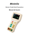
An oscilloscope was used to test the output of the system. The square peaks in Figure 69
show when the alarm is on, and when the alarm is off, the output is constant in 5V. There is a
greater frequency when the alarm is on.
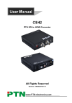
Figure 70 shows two decibel meters that were used to test the decibel range of the alarm
when it was on to meet the sound intensity requirement. The first meter simply shows an average
reading. The second meter shows three readings, the current reading, 88 dB, was at the moment
when the alarm was on, the average reading, 70 dB, is the room with the air conditioning system
on and the alarm is off, and the highest reading, 85 dB, shows the previous set of beeps.
Figure 70 Sound intensity testing for the alarm in decibels
Page 61
Project Plan
Page 62
Organization and Management
The Asklepius Pill Dispenser team comprises two mechanical engineering students, one
computer engineering student, and one electrical engineering student. The project’s management
and design tasks will be distributed among the team into the following responsibilities:
Andrew Combs (Mechanical Engineer) – Andrew is the team leader of this project. He
is responsible for making sure that the subsystems are completed and integrated on time.
He is responsible for making sure that all reports and presentations are completed on
time. He is responsible for the design and construction of the auger/casing mechanism.
Andrew will work with Jeff to make sure all of Jeff’s tasks are completed.
Jeff Wood (Mechanical Engineer) – Jeff is responsible for making the SolidWorks
drawings of the design. He is responsible for the design and construction of the device
housing, pill storage bins, slide, and pill retrieval area. He will work with Andrew to
make sure that all of Andrew’s tasks are completed.
Ethan Lilly (Computer Engineer) –Ethan is responsible for programming the
microprocessor and constructing the user interface, which includes the LCD screen,
keypad, graphical user interface and the Wi-Fi interface. Ethan will back up Emilia to
make sure she completes her tasks.
Emilia Faraj (Electrical Engineer) – Emilia is responsible for maintaining the budget.
She is responsible for the electrical designs for the power supply, the alarm, and the
sensors. She will work with Andrew in the electromechanical components of the
dispensing mechanism. She will back up Ethan to make sure he completes his tasks.
Page 63
Gantt Chart: Spring 2012
Page 64
Pert Chart: Spring 2012
Page 65
After looking at the scheduling made from last semester some revisions needed to be
made. Our group has for the most part stayed on schedule and completed task on time, but it
became apparent that some of the tasks needed some iteration before being finalize. For example,
the bin and auger/casing construction has not been completed because the design for this needs
to be slightly adjusted to make sure that our group will meet all of the requirements. Once the
design is completely finished, then it will be a simple matter of printing it out repeatedly on the
3D printer. This has also caused the slide construction to be pushed back slightly because its
dimensions relies on the bin design. The power supply and back up battery circuits have all been
printed and some have been integrated to make sure that they will meet the device’s power
requirements. All of the programming for the electronic components has been done for each part
individually except for the Wi-Fi transceiver. A large amount of integration into the final device
has been done as well. Moving forward our group will work quickly to finish up any of the tasks
left over and continue to integrate components into the final device as they are completed. A new
Gantt chart has been made showing the current plan from now until the end of the project.
New Gantt Chart
Page 66
Budget
This section contains two budgets. The first budget shows everything that our group will have to
place an order for and spend the group money on. The second budget is the supplement budget,
which shows what the prototype would cost if the group did not have access to any free items.
Here are some of the updates to the budget: the professional PCB has been ordered, a power
supply was ordered, several ICs were purchased including the keypad encoder and the half-h
motor drivers, a SchmartBoard was ordered to help with soldering the processor, the plexiglass
was first cut professionally into smaller boards that could be used in the mill and finally the
estimate for the 3D print material has been updated in the second budget. These purchases were
not expensive and our group is still in great shapes for coming in well under budget. The updated
budgets can be seen on the following pages.
Page 67
Budget
Item
Mechanical
Components
Motors
Plexiglas
Sheet
(72"x36")
Zinc Corner
Brace (4
braces in
each, screws
included)
Lock
Hinges
Bolts and
Nuts
Electrical
Components
PCB
2 Batteries
9V
Alarm
3.3 V
Regulator
15 V
Regulator
Transformer
Keypad
Encoder
Power
Supply
SN754410NE
Ics
Crystal, 4
mHz
74HC154 IC
Computer
Components
Wi-Fi
Module
LCD Screen
Keypad
Vendor
Cost/Unit
Shipping
($)
Units
Cost
Taxes
Total
Cost
($)
Date
Estimated
alltronics.com
8.95
10
0.00
0.00
89.50
12/1
Lowes
54.98
1
0.00
6.00
60.98
10/8
Lowes
2.67
3
0.00
0.00
8.01
10/8
Lowes
Lowes
4.27
2.27
1
1
0.00
0.00
0.00
0.00
4.27
2.27
12/6
12/6
Lowes
5.58
1
0.00
0.00
5.58
12/6
www.expresspcb.com
65.00
1
0.00
0.00
65.00
10/3
Walgreens
www.digikey.com
9.49
11.84
1
1
0.00
0.00
0.76
0.00
10.25
11.84
12/6
10/3
www.digikey.com
2.14
2
0.00
0.00
4.28
12/1
www.digikey.com
www.ebay.com
1.87
19.99
1
1
0.00
0.00
0.00
0.00
1.87
19.99
12/5
10/3
www.jameco.com
5.19
1
1.51
0.00
6.70
1/18
www.digikey.com
41.00
1
2.80
50.05
1/27
www.jameco.com
1.95
10
3.11
0.00
22.61
1/28
www.jameco.com
www.jameco.com
0.59
0.99
1
1
0.00
0.00
0.00
0.00
0.59
0.99
1/28
1/28
www.microchip.com
www.futurlec.com
www.futurlec.com
23.74
12.90
2.90
1
1
1
0.00
0.00
0.00
6.78
0.00
0.00
30.52
12.90
2.90
10/8
10/8
10/8
Page 68
RFID
Reader/Chips
Schmart
Board
www.parallax.com
39.99
1
0.00
0.00
39.99
11/10
www.schmartboard.com
7.99
1
7.90
0.00
15.89
1/29
Total ($)
Contingency
($)
466.98
Budget ($)
1030.00
563.02
Page 69
Budget 2
Item
Mechanical
Components
Motors
Plexiglas Sheet
(72"x36")
Plexiglas Cut
Zinc Corner
Brace
Lock
Hinge
Bolts and Nuts
Auger/Casing
Material
Electrical
Components
PCB
2 Batteries 9V
Alarm
3.3 V Regulator
15 V Regulator
Power Supply
Transformer
Force Sensors
Keypad Encoder
SN754410NE
Ics
Crystal, 4 mHz
74HC154 IC
PCB (etched)
Computer
Components
Microprocessor
Wi-Fi Module
LCD Screen
Keypad
RFID
Reader/Chips
Schmart Board
Vendor
Cost/Unit
($)
Units
Shipping
Cost
Taxes
Total
Cost ($)
Date
Estimated
alltronics.com
8.95
10
0.00
0.00
89.50
12/1
Lowes
Landis Glass Co.
54.98
NA
1
NA
0.00
10.00
4.39
0.00
59.37
10.00
10/8
1/30
Lowes
Lowes
Lowes
Lowes
2.67
4.27
2.27
5.58
3
1
1
1
0.00
0.00
0.00
0.00
0.64
0.56
0.03
0.45
8.65
4.83
2.30
6.03
10/8
12/6
12/6
12/6
Engineering Department
5.00
40
0.00
0.00
200.00
10/13
www.expresspcb.com
Walgreens
www.digikey.com
www.digikey.com
www.digikey.com
www.digikey.com
www.ebay.com
www.interlinkelec.com
www.jameco.com
65.00
9.49
11.84
2.14
1.87
41.99
19.99
6.44
5.19
1
1
1
2
1
1
1
1
1
0.00
0.00
0.00
0.00
0.00
4.00
0.00
0.00
1.51
0.00
0.76
0.00
0.00
0.00
4.06
0.00
0.00
0.00
65.00
10.25
11.84
4.28
1.87
50.05
19.99
0.00
6.70
10/3
12/6
10/3
12/1
12/5
1/26
10/3
10/20
1/18
www.jameco.com
www.jameco.com
www.jameco.com
Engineering Department
1.95
0.59
0.99
4
10
1
1
3
3.11
0.00
0.00
0
0.00
0.00
0.00
0
0.00
0.59
0.99
8.00
1/28
1/28
1/28
1/30
www.microchip.com
www.microchip.com
www.futurlec.com
5.00
23.74
12.90
4
1
1
0.00
0.00
0.00
0.00
6.78
0.00
2.90
39.99
0.00
10/8
10/8
10/8
www.futurlec.com
2.90
1
0.00
0.00
0.00
10/8
www.parallax.com
www.schmartboard.com
39.99
7.99
1
1
0.00
7.90
0.00
0.00
0.00
15.89
11/10
1/29
Total ($)
Contingency
($)
619.02
Budget ($)
1030.00
410.98
Page 70
References
Page 71
1.Pueblo, Colorado, Federal Information Center. Medication advice for seniors.
(http://www.pueblo.gsa.gov/cic_text/health/meds4old/697_old.html)
2. Minnesota Board on aging.
(http://www.mnaging.org/pdf/Prescription%20Drug%202002.PDF)
3. Shopping page for a competing pill dispenser at Wheel Chair Select.
(http://www.wheelchairselect.com/Telemergency-royalty100-VCW1000.html)
4. Dimensions Guide. (http://www.dimensionsguide.com/average-kitchen-dimensions/)
5. RadioShack’s website. (http://www.radioshack.com/product/index.jsp?productId=2103667)
6. Shigley’s Mechanical Engineering Design Ninth Edition. Page 416.
Page 72
Appendices
Page 73
Appendix A
Microprocessor
Page 74
Page 75
Page 76
Page 77
PROTOTYPE CODE:
/*
Ethan Lilly
Last Modified: 12/5/2011
This program is used with our most recent prototype. It will step the motor 7.2 degrees
and then continuously check the A/D converter for about a second for any changes in the
sensor output. If a pill is dropped on the sensor the program enters an empty infinite
loop that causes the motor to stop dispensing.
*/
#include <p30f6015.h>
#include <math.h>
#define CrystalFreq 7378200
#define Millisec CrystalFreq/7378
int delay, delay2;
//Functions and Variables with Global Scope:
void ADC_Init(void);
void stepMotor()
{
int delay = 0;
int delay2 = 0;
PORTE = 0x0003;
Page 78
for(delay2=0;delay2<2;delay2++){
for(delay=0;delay<10000;delay++){}
}
PORTE = 0x0006;
for(delay2=0;delay2<2;delay2++){
for(delay=0;delay<10000;delay++){}
}
PORTE = 0x000C;
for(delay2=0;delay2<2;delay2++){
for(delay=0;delay<10000;delay++){}
}
PORTE = 0x0009;
for(delay2=0;delay2<2;delay2++){
for(delay=0;delay<10000;delay++){}
}
}
//Functions:
//ADC_Init() is used to configure A/D to convert 16 samples of 1 input
//channel per interrupt. The A/D is set up for a sampling rate of 1MSPS
Page 79
//Timer3 is used to provide sampling time delay.
//The input pin being acquired and converted is AN7.
void ADC_Init(void)
{
TRISB = 0xFFFF;
//Port B is input
ADPCFG = 0xFFFB;
//10th channel is sampled and coverted
ADCON1 = 0x00E0;
//ADC off, output_format=INTEGER
//Manual start of convesion
//Manual start of sampling
ADCHS = 0x0002;
ADCSSL = 0;
//Connect RB10 on AN10 as CH0 input
//No scan
ADCON3 = 0x1F02;
ADCON2 = 0;
//ADCS=3 (min TAD for 10MHz is 3*TCY=300ns)
//Interrupt upon completion of one sample/convert
ADCON1bits.ADON = 1;
//ADC on
}
int main(void)
{
ADC_Init();
PORTE = 0;
TRISE = 0x0000;
int result = 0;
//Initialize the ADC
//Set all of PORTE to 0
//make these ports set to output
//variable used to hold the initial sensor reading after each motor step
int tempResult = 0;
reading
//used to find the difference between result and the most recent sensor
int pillDropped = 0;
dropped
//a boolean used to terminate the while loop once a pill has been
Page 80
while(pillDropped == 0)
{
ADCON1bits.SAMP = 1;
//Start sampling (SAMP=1)
while (!ADCON1bits.DONE){}
ADCON1
result = ADCBUF0;
//Wait for DONE bit in
//Store result
stepMotor();
//Steps the motor 7.2 degrees
for(delay2=0;delay2<1;delay2++){
check the sensor
//enter a for loop that is used to
for(delay=0;delay<20000;delay++){
ADCON1bits.SAMP = 1;
//Start sampling (SAMP=1)
while (!ADCON1bits.DONE){}
//Wait for DONE bit in ADCON1
tempResult = result - ADCBUF0;
initial result and the most recent reading
//Find the difference between the
if(tempResult < 0)
tempResult = tempResult*-1;
//If the difference is negative, change
the sign
if(tempResult > 25)
pill was dropped
//is the difference is larger than 25, then a
{
pillDropped = 1;
}
}
}
}
Page 81
while (1) {}
sleep-like state
//endless loop used to put the processor in a
return 0;
}
Page 82
Appendix B
Wi-Fi Transceiver Module
Page 83
Page 84
Page 85
Page 86
Page 87
Page 88
Page 89
Page 90
Page 91
Appendix C
LCD Screen
Page 92
Page 93
Page 94
Page 95
Page 96
Page 97
Appendix D
Keypad
Page 98
Page 99
Page 100
Page 101
Page 102
Page 103
Page 104
Page 105
Page 106
Page 107
Appendix E
RFID Reader
Page 108
Page 109
Page 110
Page 111
Page 112
Page 113
Page 114
Appendix F
Alarm
Page 115
Page 116
Page 117
Appendix G
Force Sensors
Page 118
Page 119
Page 120
Page 121
Page 122
Appendix H
Motor
Page 123
Page 124
Appendix I
Real Time Clock
Page 125
Page 126
Page 127
Page 128
Page 129
Appendix J
Power Supply
Page 130
Page 131
Page 132
Page 133
Page 134
Page 135
Page 136
Requirements
Specification
Page 137
Overview
The number of people over 65 is increasing due to the aging of the Baby-Boomers, the
generation of people born after World War Two. One of the greatest demands of this generation
is medicine. People over the age of 65 buy 30 percent of all prescription drugs and 40 percent of
all over-the-counter drugs (1). The average number of pills taken daily by people over the age of
65 is 2.9. More than one in five seniors take five or more different prescription drugs every day.
Here is a table showing the number of drugs taken daily by seniors (2).
Table 1. Number of pills taken by people over 65
Pills Taken
0
1-2
3-4
5+
Percentage of Seniors
18%
36%
25%
21%
Keeping track of medication is a burden for the elderly. Arthritis, poor eyesight, poor
hearing, and memory lapses can make it difficult for some older people to take their medications
correctly. Studies have shown that between 40 and 75 percent of older people don't take their
medications at the right time or in the right amount (1). The consequences for not taking
medication properly can be fatal. When two or more drugs are mixed in the body, they may
interact with each other and produce uncomfortable or even dangerous side effects (1).
Medication users desperately need a product to keep track of their medication and administer the
correct amount at the correct time.
Some people organize medication by putting it into a small container that is partitioned
into seven smaller containers, each representing a different day of the week. This method is very
tedious and also fails at organizing many varieties of medication. It does nothing to help people
remember to take their medication. There is another device that allows a user to organize pills
into 29 separate bins and set a timer that will alert the user when it is time to take their
medication (3). The problem with this is that each bin only has enough space for three pills at the
most, and the alarm can only be set to go off once a day. It also does not dispense the pills, but
leaves them accessible to the user.
The Asklepius medicine dispenser will solve these problems, making it easier to organize
medication. It will be quick, easy to setup, and will allow a person to stay organized for a month
at a time. The device will also sound an alarm when it is time to take the medication. The
Asklepius medicine dispenser is the superior alternative.
Page 138
Problem Statement
Taking the correct medication at the correct time is challenging for the elderly and can be
a burden on loved ones. Not taking medication properly can be very dangerous and potentially
fatal. The age 65 and over market demands a cost effective device that will keep track of and
dispense the proper amount of medication at the right time. The device would serve solid, orally
ingested tablets and capsules. Throughout the report, this medication will be referred to with the
term pills.
Customer Needs
The caretaker is the person who sets up the device and is assumed to have the technical
skills of an average person, meaning anyone who can operate a computer to browse the internet
and do basic things such as shopping online. The patient is the person receiving pills dispensed
from the device and might have mental difficulties. The caretaker will organize pills into the
device and then set it up to dispense a certain amount of pills at specified times. The customer
needs shown below give a very general overview of the requirements that will be defined in
more detail in the technical specifications section.
•
The device needs to consistently dispense the amount of pills entered by the caretaker at
the time entered by the caretaker. It needs to be completely reliable to ensure the safety of
the patient.
•
The device needs to service a large variety of pills. If there are many types of pills that
are not serviceable by the device, then the device will not appeal to a large percentage of
its target market.
•
The device needs to be light enough for an average person to carry easily.
The device needs to be portable and easy to handle. It needs to fit comfortably on an
average kitchen counter top, which has 0.46 m (18 in) of space between the counter top
and upper cabinets (4).
•
The device needs to remain active at all times. Since the device will serve a critical
application, the device needs to remain in operation in the event of a power failure.
•
The device needs to alert the patient when a dosage is ready. It needs to use an alarm
instead of more technically advanced methods due to the inferior technical knowledge of
the patient.
•
The device needs to be easy for the average person to set up. This means that it needs to
be easy for the average person to insert pills into the device and program when they
should be dispensed by the device.
Page 139
•
The internal components of the device need to be secure. This is to prevent unwanted
access to the pills inside the device.
•
The device needs to hold a month’s supply of pills. This will increase the ease of use for
the caretaker.
•
The device needs to notify the caretaker when the patient does not take their pills.
Operational Description
Pills Loading Process:
•
Unlock and open the door of the device to access pill storage bins inside the device.
•
Insert each type of pill into one of the storage bins. Be sure to only put one type of pill
into each bin.
•
Close and lock the device.
•
Make sure the device is plugged into a power outlet and the power is switched on.
Programing Process:
•
Program the device using a laptop computer wirelessly connected to the device.
•
Specify the type of pills in each storage bin.
•
Specify the doses and the times these doses are to be taken.
•
Enter the email address you would like to be notified at in the case that the patient does
not receive their pills.
Patient Pill Retrieval Process:
•
Place RFID chip within four inches of the RFID reader to gain access to the pill retrieval
area. This will also turn the alarm off.
•
Grab pills from the pill tray.
Page 140
Technical Requirements
A pills dispenser project, titled PEZ, was completed by one of the 2010-2011 Senior Design
groups. Some of our technical specifications were selected with intentions of making
improvements on last year’s project.
•
It will successfully provide the proper pills specified by the caretaker in a minimum of 40
out of 40 tests.
It will be able to service pills ranging from 10 mg to 1 g. For the purposes of these
technical requirements, pills’ sizes will be defined by two dimensions and a shape. One
dimension will be the smallest dimension of the pill. The other will be the largest
dimension of the pill. The device will be able to operate on pills with small dimensions
between 0.5 cm (0.2 in.) and 1 cm (0.4 in.) It will be able to operate on pills with large
dimensions underneath 2.5 cm (1 in.) The device will operate with pills shaped as tablets,
capsules, and ovals.
•
It will weigh less than 130 N (30 lbf).
•
Its dimensions will be less than 0.46 m (18 in) high, 0.38 m (15 in) wide, and 0.38 m (15
in) long. Last year’s dimensions were, 0.54 m (21.25 in), 0.44 m (17.5 in), and 0.48 m
(19 in) respectively. The spatial dimensions of the object are defined as the smallest cube
needed to encapsulate the object. For example, the height of the device is the distance
from the base of the device to the tallest point on the device.
•
A back up battery will be used as a fail-safe in the event of a power outage. It will be able
to power the device for one week.
•
The device will have an alarm that will sound when the pill is being dispensed. The alarm
will have an intensity between 80 and 90 dB.
•
An average person will be able to program the device in less than 5 min.
•
The device will have a lock to prevent unwanted access to the interior of the device.
•
The device will store 90 pills of each medication.
•
The device will be able to connect to a WEP, WPA and WPA2 secured Wi-Fi networks.
•
The device will email the caretaker when the patient's pills are not taken within 30
minutes of the alarm initially sounding.
Page 141
Table 2. Technical Specifications
No.
1
2
3
4
5
6
7
8
9
10
11
Metric
Total Weight
Device Size
Time to program a
medication
Amount of pills in each bin
Intensity of the alarm
Time for battery to
discharge
Weight of pills
Lock
Successful dispensing tests
Time to alert caretaker
Wi-Fi connection
Value
< 130
0.46 (H) x 0.38 x 0.38
Units
N
m
<5
90 max
80-90
min
pills
dB
1
10-1000
Locked/Unlocked
100
30
Connected/Unconnected
week
mg
%
min
1
2
3
4
5
6
7
8
9
10 11
Total Weight
Device size
Time to program a medication
Amount of pills
Intensity of the alarm
Time for battery to discharge
Weight of pills
Lock
Successful dispensing tests
Time to alert the caretaker
Wi-Fi connection
Table 3. Needs-Metrics Matrix
●
●
1
Portable and easy to handle ●
2
Easy to program
3
Large variety of medication
4
Alert the patient when a dosage is ready
5
Remain active at all times
6
Month's supply of medication
7 Internal components of the device only accesible to the caretaker
8
Consistently provide medication
9
Alert the caretaker if a dosage has not been taken
●
●
●
●
●
●
●
●
●
Page 142
Deliverables
•
Pills dispenser device
•
Systems capability specifications
•
Detailed schematic and final report on device functionality
•
User manual
•
Parts manual and corresponding budget
Testing Plan
•
The general testing procedure for the efficacy of the dispensing mechanism of the device
will be carried out as follows:
•
•
•
Pills will be inserted into the device. For the purpose of this test, we will not limit
ourselves to actual pills, we will allow for other forms of solid, orally ingested
tablets and capsules such as mints or candies.
The device will be programmed to dispense the pills at a set time. The pills will
then have to be dispensed within five minutes of the set times.
The success criterion described in the following paragraph will be determined by
visual observation by one of the team members.
The success of the test is dependent on two factors. First the operation will be counted
as being on time if the pills are dispensed within five minutes of the programmed time.
Second, the operation must result in the amount and type of pills being dispensed as
programmed by the caretaker. If both of these requirements are successfully met, then the
result of the test is successful. Otherwise, the test is not successful.
40 tests will be performed which will fall into one of four categories. Each category
tests pills that fall within a certain range of masses. The categories are: 10 mg to 250 mg,
250 mg to 500 mg, 500 mg to 750 mg, and 750 mg to 1 g. For example, a pill that weighs
100 mg is a category one pill. The 40 tests will be divided evenly between these four
categories, meaning that 10 tests will be done with pill sizes in only one category. The
device must perform successfully in 40 consecutive tests, with the variability of pill types
as described above.
•
The device will be weighed with a bathroom scale to determine that it meets the weight
requirement. The device will be weighed four times. The mean of these measurements
must be under the requirement listed in the technical requirements.
Page 143
•
The device will be measured to determine that it meets the volume requirements. These
measurements will be made with a measuring tape. The height, width, and length of the
device will be measured four times each. The mean of these measurements must be less
than requirements listed in the technical requirements. For example, the height of the
device will be measured four times with a measuring tape. These four measurements will
be averaged and must be less than 0.46 m. The definition of the height, weight, and
length is described in the technical requirements.
•
The life of the back-up battery will be tested. The battery will be fully charged and the
device will undergo eight days’ worth of dispensing in a 24 hour period. This assumes the
worst case scenario of dispensing a pill from every bin three times a day, which adds up
to dispensing a pill from each bin 24 times. We will do eight days’ worth rather than
seven to account for the total time throughout the week that the device is not dispensing.
•
The intensity of the alarm will be measured with a digital-display sound-level sensor
from radio shack (5). The sensor reads from 50 to 126 dB and will be placed within one
meter of the device. The alarm intensity will be measured from within this distance 10
times. The mean of these measurements must fall within the range listed in the technical
requirements.
•
Random people will be asked to program the device. The number of people that perform
this test must at least be above 10. The time it takes a person to program the device will
be recorded by one of the team members. The time needed to program the device does
not include the time taken to learn how to use the device. The programming time of all of
the testers will be averaged. To successfully meet the ease of use requirement, this
average must be under five minutes.
•
To determine that a container holds a month’s supply of pills, 90 pills will be poured into
a container. If all of the containers are the same size, then this test will only need to be
performed on one of the containers. If the containers are different sizes, then this test will
be performed on the smallest container. The pills used in this test must be category four.
To successfully meet this test, 90 pills must fit into the container without spilling over the
top.
•
We will connect the device to a WEP, WPA and WPA2 secured Wi-Fi network five
times each. If the device successfully connects to the Wi-Fi network five times
consecutively for each type, it has passed this requirement.
To determine if the device successfully emails the address given by the caretaker when pills are
not taken, we will purposefully allow the alarm time to run out 10 times after dispensing pills. If
an email is sent for all 10 tests consecutively, this requirement has been met. For normal
operation, the time that the device would wait before sending an email will be 30 minutes;
however, for the purpose of this test that time will be reduced to 1 minute.
Page 144