1
CHAPTER 4 USAGE
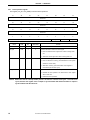
4.4 Clearing the Timer Count Value Timer
The values of the internal timer count register can be cleared to 0 with a single write operation during counting.
This operation can be used during clearing of the watchdog timer. (The TOUT signal is not asserted if writing is
performed at least once before the timer counts out.)
(It's used as Watchdog timer: Multimedia Processor for Mobile Applications System Control/GeneralPurpose I/O Interface User’s Manual chapter 3.2.8).
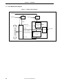
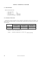
(1) Clears the timer count:
TCR_CLR = 1 (bit 1 of xxx_CLR register)
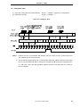
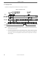
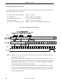
Figure 4-4. Clearing the Timer Count Value Timer
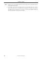
<1> This bit is automatically cleared to “0” after the timer count value is cleared (TCR_CLR = 1).
Notes 1. Registers are set in synchronization with PCLK, and real counting occurs in synchronization with TIN.
PCLK and TIN are asynchronous.
2. After the timer count value is cleared, the timer count is actually cleared one PCLK cycle + two or three
TIN cycles later because the value is specified to be cleared in synchronization with PCLK, but is
actually cleared in synchronization with TIN.
3. When the timer count value is cleared, the signal is output from the register for one PCLK cycle, and
clearing takes effect in synchronization with TIN (this takes three cycles). Next, a clear signal in
synchronization with TIN is output for one cycle and is synchronized with PCLK again (this takes four
cycles). The timer clear register is then cleared to 0, and the clear operation is complete. Therefore, a
timer count that is cleared within five PCLK cycles + four TIN cycles is ignored. For the watchdog timer,
set the timer value setting register (TMSET bits) to a value of at least (5 PCLK cycles) + (4 TIN cycles).
User’s Manual S19266EJ3V0UM
21