1
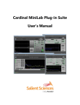
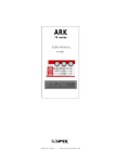
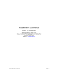
Bode 100 - Application Note Passive Filter Design with QuickFil Page 1 of 18 Passive Filter Design with QuickFil and the Bode 100 QuickFil 5.1 Software standard for PC filter design By Florian Hämmerle © 2011 Omicron Lab – V1.0 Visit www.omicron-lab.com for more information. Contact [email protected] for technical support. Smart Measurement Solutions Bode 100 - Application Note Passive Filter Design with QuickFil Page 2 of 18 Table of Contents 1 Executive Summary ....................................................................................................3 2 Task ..............................................................................................................................3 3 Filter Design with QuickFil .........................................................................................4 3.1 About QuickFil .........................................................................................................4 3.2 Bandpass Filter Design ...........................................................................................4 3.2.1 Filter Type and Specifications ............................................................................4 3.2.2 Circuit Manipulation ...........................................................................................8 3.2.3 Circuit Analysis ................................................................................................11 4 Filter Measurement ...................................................................................................13 4.1 Device Setup .........................................................................................................13 4.2 Calibration .............................................................................................................14 4.3 Measurement ........................................................................................................15 5 Results .......................................................................................................................16 6 Conclusion .................................................................................................................18 Note: Basic procedures such as setting-up, adjusting and calibrating the Bode 100 are described in the Bode 100 user manual. Note: All measurements in this application note have been performed with the Bode Analyzer Suite V2.31. Use this version or a higher version to perform the measurements described in this application note. You can download the latest version at http://www.omicron-lab.com/downloads.html. Smart Measurement Solutions Bode 100 - Application Note Passive Filter Design with QuickFil Page 3 of 18 1 Executive Summary This application note targets the design and analysis of standard filter types such as high pass, low pass and band pass filters. It is demonstrated how to design a passive bandpass filter using the freeware filter design software QuickFil1. The designed filter is realized using standard value components and the filter characteristics are then measured using the Bode 100. Finally the measured filter characteristics are compared with the calculated values from QuickFil. 2 Task A passive bandpass filter with the following characteristics shall be designed: Centre frequency: Passband bandwidth: Passband loss Filter degree The designed filter shall be built and the characteristics be measured. The measured characteristics will be compared with the theoretical values. 1 More information at: http://www.omicron-lab.com/filter-design-software.html Smart Measurement Solutions Bode 100 - Application Note Passive Filter Design with QuickFil Page 4 of 18 3 Filter Design with QuickFil 3.1 About QuickFil QuickFil is a software for designing passive electronic filters. QuickFil supports many types of filters and different approximations: Types of Filters: Lowpass Highpass Bandpass Bandstop Allpass Asymmetric bandpass filters Parametric bandpass filters Approximations: Butterworth (maximally-flat filters) Chebyshev (equal-ripple filter) Inverse Chebyshev Elliptic (Cauer) Bessel (maximally flat delay) Modified Bessel General Equal-ripple approximation General maximum-flat approximation Note: If you plan to run QuickFil on Windows Vista or Windows 7 you have to use a small workaround. Details on this are described in the QuickFil Installation Guideline (go to http://www.omicron-lab.com/filter-design-software.html in the download tab) 3.2 Bandpass Filter Design The following chapters are structured like a step by step guideline on how to design a filter using QuickFil. 3.2.1 Filter Type and Specifications The first step is to define the filter type and approximation. After starting QuickFil the main screen is shown. By clicking on <Filtertype> the type of filter and the approximation method can be chosen as shown in the following figures: Smart Measurement Solutions Bode 100 - Application Note Passive Filter Design with QuickFil Page 5 of 18 In the QuickFil Main screen the option <Filtertype> can be chosen: The Filtertype screen appears and the <Type> is set to <Bandpass> and the <Approximation > to <Chebychev>: Note: By clicking on <Quit> one can return to the main screen! Smart Measurement Solutions Bode 100 - Application Note Passive Filter Design with QuickFil Page 6 of 18 In the Main screen the <Specification> option can be chosen to enter the specification values which define the filter performance: Input values defining the filter properties. The variable value is indicated by the ◄ symbol. This option enables to enter the filter bandwidth as relative values. As described in the beginning of the document, a filter with a centre frequency of is defined. The relative passband bandiwdth is defined to be and the relative stopband bandwidth is defined to be . By defining the <Stopband loss> to be the variable (changing) value the filter degree can be defined to be . This results in a calculated stopband loss of . <Quit> returns to the Main screen and by choosing the option <passive_Design> in the Main screen, QuickFil proposes the design and values for the passive filter defined in the specification screen: Smart Measurement Solutions Bode 100 - Application Note Passive Filter Design with QuickFil Page 7 of 18 By clicking on <Dual circuit> QuickFil calculates the component values for the dual design. In this case the dual design has some advantages for later circuit manipulation. Choosing the option <Output circuit> shows the current design and the calculated component values: appnote filter -------------1 ....R.... . . 2 ....C.... . . 3 ....L.... . . 4 . C . . 5 . L . . 6 ....C.... . . 7 ....L.... . . 8 ....R.... 50.000 000 Ohm 142.763 346 nF 3.354 037 uH 1.206 170 nF 396.986 807 uH 142.763 346 nF 3.354 037 uH 50.000 000 Smart Measurement Solutions Ohm Bode 100 - Application Note Passive Filter Design with QuickFil Page 8 of 18 3.2.2 Circuit Manipulation The default design proposed by QuickFil contains three inductors with two different inductance values ( ). QuickFil offers a Norton's transformation functionality to modify component values without affecting the filter characteristics. In the following is explained how the filter can be modified to achieve three similar inductors. The Norton's transformation option can be found by first choosing the <Manipulation and analysis> option in the Passive design screen. Choosing the <Norton's transformation> option opens the Norton's transformation screen: Smart Measurement Solutions Bode 100 - Application Note Passive Filter Design with QuickFil Page 9 of 18 The transformation always works from top to down. We now want to perform a transformation in a way that the inductor L5 gets the same inductance value as the inductor L3. This can be done by setting the <Component No.> to 5. This means that component No. 5 will be changed. Since we want the inductor L5 to have the same value as the inductor L3 the <Nominal compon.> has to be set to 3. QuickFil now calculates the transformation factor which is displayed in the <Nominal factor> field: In addition the <Kind of circuit> is set to TEE as this gives a better structure for the second transformation. The transformation now has to be made active by clicking on <Nominal factor>. This means that the calculated transformation factor is applied to the circuit. This leads to the following screen: The first two inductors now have the same inductance value. The same transformation can be applied to the third inductor as follows. Smart Measurement Solutions Bode 100 - Application Note Passive Filter Design with QuickFil Page 10 of 18 Clicking two times on <Next component combination> marks the right components. Now the <Component No.> field is set to 8 as we want to change the value of the last inductor at position 8. The <Nominal compon.> value is set to 6 as we want the inductor 8 to have the same inductance value as the inductor 6. Performing the transformation by clicking on <Nominal factor> leads to the final circuit design. The circuit and component values can be displayed by clicking on <Quit> and <Output circuit>: appnote filter -------------1 ....R.... . . 2 ....L.... . . 3 . C . . 4 ....C.... . . 5 . L . . 6 . C . . 7 ....C.... . . 8 . C . . 9 ....L.... . . 10 ....R.... 50.000 000 Ohm 3.354 037 uH 157.213 986 nF 1.553 177 uF 3.354 037 uH 171.371 516 nF 1.553 177 uF 157.213 986 nF 3.354 037 uH 50.000 000 Ohm The three inductors now have the same inductance values which can be advantageous for the practical design. Smart Measurement Solutions Bode 100 - Application Note Passive Filter Design with QuickFil Page 11 of 18 The practical design is built using standard component values. The capacitance values were achieved by series and parallel combination of standard capacitors. The used component values are: Component L2, L5, L9 C3, C8 C4, C7 C6 Calculated Value 3.354 µH 157.213 nF 1.553 µF 171.371 nF Used Value 3.3 µH 158 nF 1,55 µF 172 nF Assembled bandpass filter: 3.2.3 Circuit Analysis QuickFil offers tools to analyze the designed filter. In the Manipulation and Analysis screen the option <Circuit analysis> can be chosen. Smart Measurement Solutions Bode 100 - Application Note Passive Filter Design with QuickFil Page 12 of 18 In the Circuit Analysis screen the desired property and plot settings can be set. Clicking on <Graph> starts the plot window and shows the transfer function as shown in the following figure. Smart Measurement Solutions Bode 100 - Application Note Passive Filter Design with QuickFil Page 13 of 18 4 Filter Measurement The assembled bandpass filter transfer function shall be measured with the Bode 100. In the following is shown step by step how to configure and calibrate the Bode 100 for the filter measurement. 4.1 Device Setup The transfer function of the bandpass filter can be measured in the Frequency Sweep Mode of the Bode Analyzer Suite. To do so the Bode Analyzer Suite has to be started and the Frequency Sweep Mode has to be selected by clicking on the Frequency Sweep Mode icon. We want to measure the magnitude and phase of the filter. Therefore trace 1 is set to Measurement Gain, Format Mag(dB) and trace 2 to Measurement Gain, Format phase(°) as shown in the following figures: Start and stop frequency are set to 100 kHz and 350 kHz. The attenuator for cannel 1 to 0 dB and the attenuator for channel 2 to 10 dB. The receiver bandwidth is set to 30 Hz: Smart Measurement Solutions Bode 100 - Application Note Passive Filter Design with QuickFil Page 14 of 18 The 50 Ohm termination has to be switched on as the filter is designed to be terminated. To do so, open the configuration window and click on the termination switch (see figure below): The Bode 100 is now ready to perform the measurement. To remove the influence of the connection cables on the measurement results it is advisable to perform a calibration before measuring the filter. 4.2 Calibration A thru calibration removes the influence of the cables on the measurement. To do so, the two cables from output and channel 2 have to be connected together using the thru connector as shown in the picture below. Smart Measurement Solutions Bode 100 - Application Note Passive Filter Design with QuickFil Page 15 of 18 After connecting the cable the thru calibration can be done by clicking on User Calibration or Probe Calibration Start the calibration by pressing start: 4.3 Measurement After performing the calibration, the thru connection is replaced by the bandpass filter as shown in the picture below. Now the measurement can be started by pressing the single sweep button. Smart Measurement Solutions Bode 100 - Application Note Passive Filter Design with QuickFil Page 16 of 18 5 Results Performing the measurement described above leads to results as shown below. The first graph shows the amplitude gain in decibel and the second graph the phase in degree. 0 -10 TR1/dB -20 -30 -40 -50 -60 -70 -80 100K 150K 200K 250K 300K 350K 250K 300K 350K f/Hz TR1: Mag(Gain) 200 150 TR2/° 100 50 0 -50 -100 -150 -200 100K 150K 200K f/Hz TR2: Phase(Gain) Comparing these results with the calculations in QuickFil shows that the passband loss is higher than calculated. The reason for this are the limited quality factors of the components used to assemble the filter. QuickFil offers a feature to estimate this influence. In the circuit analysis screen are input fields for the inductor quality factor and the capacitor quality factor. The components used for the assembled filter have an approximate quality factor of Inductors: Capacitor combinations: Smart Measurement Solutions Bode 100 - Application Note Passive Filter Design with QuickFil Page 17 of 18 The figure below shows how the quality factors are entered into QuickFil. Inductor quality factor Capacitor quality factor When considering the quality factors of the components the calculated transfer characteristic results as shown in the following graph: On the next page there is a direct comparison between measured and calculated data where the quality factors are taken into consideration Smart Measurement Solutions Bode 100 - Application Note Passive Filter Design with QuickFil Page 18 of 18 Calculated gain magnitude in dB: Measured gain magnitude in dB: 0 -10 TR1/dB -20 -30 -40 -50 -60 -70 -80 100K 150K 200K 250K 300K 350K f/Hz TR1: Mag(Gain) 6 Conclusion The first part of this application note shows how to design passive filters using the filter design software QuickFil. QuickFil offers many functions for passive filter design e.g. Norton's transformation to optimize the filter design. The second part of the application note shows how to measure the filter characteristics of the designed bandpass filter using the Bode 100. It is shown how to terminate the filter correctly using the internal 50 Ohm resistance of the Bode 100. The measured and calculated results match very well when the quality factors of the used components are considered for the calculation of the transfer function. It is therefore very important to have high quality components for the passive filter design. Smart Measurement Solutions