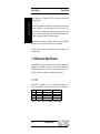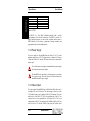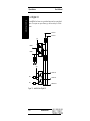
1
miniHiPerCam
Hardware Manual
Revision 1B
Revision History
Revision
1A
1B
Changes
First Edition,
valid for Hardware revision 0A,
0B, 0C, 1A
Valid for Hardware 2A, 3A
Date
07.09.99 GM
26.10.99 GM/UW
WARNING ! This equipment generates and can radiate radio frequencies. If not
installed in accordance with the instruction manual, it may cause interference to
radio communications. The equipment has not been tested for compliance with
the limits for class A computing devices, pursuant to subpart J of part 15 of FCC
rules, which are designed to provide reasonable protection against such
interference, but temporary usage is permitted as per regulations. Operation of
this equipment in a residential area is likely to cause interference, in which case
the user, at his own expense is required to take whatever measures may be
required to shield the interference.
DISCLAIMER! The information in this document has been carefully checked
and is believed to be entirely reliable. However, no responsibility is assumed for
inaccuracies. ELTEC reserves the right to make changes to any products to
improve reliability, function or design. ELTEC does not assume any liability
arising out of the application or use of any product or circuit described in this
manual; neither does it convey any license under its patent rights nor the rights
of others. ELTEC products are not authorized for use as components in life
support devices or systems intended for surgical implant into the body or
intended to support or sustain life. Buyer agrees to notify ELTEC of any such
intended end use whereupon ELTEC shall determine availability and suitability
of its product or products for the use intended.
ELTEC points out that there is no legal obligation to document internal
relationships between any functional modules, realized in either hardware or
software, of a delivered entity.
This document contains copyrighted information. All rights including those of
translation, reprint, broadcasting, photomechanical or similar reproduction and
storage or processing in computer systems, in whole or in part, are reserved.
Mircosoft®, Windows NT®, Windows CE® and Visual C++® are registered
trademarks of Microsoft Corporation.
Datalight® is a registered trademark of Datalight, Inc. FlashFX (TM) is a
trademark of Datalight, Inc.. Other brands and their products are trademarks of
their respective holders and should be noted as such.
© 1999 ELTEC Elektronik GmbH, Mainz
User's Manual
Table of Contents
Table of Contents
1
Specification...................................................................... 1—1
1.1
Main Features ............................................................... 1—1
1.2
General Description....................................................... 1—1
1.3
Mechanical Specification................................................ 1—2
1.3.1
I/O........................................................................ 1—2
1.3.2
I/O Mechanical ...................................................... 1—3
1.4
Technical Details ........................................................... 1—3
1.4.1
CPU...................................................................... 1—3
1.4.2
Power Supply........................................................ 1—4
1.4.3
Video Output ......................................................... 1—4
1.4.4
Digital I/O.............................................................. 1—6
1.4.5
Memory / File system............................................. 1—7
1.4.6
DRAM................................................................... 1—7
1.4.7
Flash EPROM ....................................................... 1—8
1.4.8
Video Capturing Modes.......................................... 1—8
1.4.9
Lens Adjustment.................................................... 1—8
1.4.10 Address Map......................................................... 1—9
I
1.5
Connectors ................................................................. 1—10
1.6
System Parameters ..................................................... 1—11
1.6.1
Environmental Conditions..................................... 1—11
1.6.2
Power Requirements ........................................... 1—11
miniHiPerCam
I
Table of Contents
1.6.3
Dimensions ......................................................... 1—11
1.6.4
Regulations/Compliance ...................................... 1—13
1.7
2
3
II
User's Manual
Image Sensor.............................................................. 1—13
Operating System.............................................................. 2—1
2.1
Flash File System.......................................................... 2—1
2.2
Bootloader .................................................................... 2—1
2.3
Updates ........................................................................ 2—2
2.4
Registry ........................................................................ 2—2
Installation......................................................................... 3—1
3.1
First Steps .................................................................... 3—1
3.2
Connect the miniHiPerCam to the Host ........................... 3—1
3.3
Bootloader Configuration................................................ 3—7
3.4
Cmd Shell ................................................................... 3—10
3.5
Connect to the miniHiPerCam Webserver ..................... 3—13
3.6
Software Development ................................................. 3—15
3.7
Troubleshooting........................................................... 3—16
3.7.1
Bootloader Version .............................................. 3—16
3.7.2
Revision Information............................................ 3—16
3.7.3
Boot Parameters.................................................. 3—17
3.7.4
Kernel Version..................................................... 3—18
3.7.5
Registry Contents................................................ 3—18
3.7.6
Flash File System Contents.................................. 3—19
miniHiPerCam
II
User's Manual
Table of Contents
List of Tables
Table 1-1: Video out with VGA Standard (8 bit/pixel color).......................1—2
Table 1-2: Connectors .........................................................................................1—3
Table 1-3: CPU.....................................................................................................1—4
Table 1-4: Video LUT .........................................................................................1—5
Table 1-5: Default LUT Setup ...........................................................................1—5
Table 1-6: Digital I/O Characteristics...............................................................1—7
Table 1-7: Main Memory ....................................................................................1—7
Table 1-8: VGA Connector (DB15 female)...................................................1—10
Table 1-9: Serial Connector (9-Pin D-Sub, male).........................................1—10
Table 1-10: Ethernet Connector (RJ45 Jack).................................................1—10
Table 1-11 OV7610 Sensor Characteristics ..................................................1—13
III
miniHiPerCam
III
Table of Contents
User's Manual
List of Figures
Figure 1-1: Block Diagram.................................................................................1—3
Figure 1-2: miniHiPerCam Digital I/O............................................................1—6
Figure 1-3: Dimensions.....................................................................................1—12
Figure 1-4:Tripod Attachment ........................................................................1—12
Figure 3-1 Location of Connectors on the Back Panel..................................3—2
Figure 3-2 Connecting miniHiPerCam to Host (without Hub)....................3—3
Figure 3-3 10BaseT Hub Network Connection ..............................................3—4
Figure 3-4 10BaseT/10Base2 Hub Network Connection..............................3—5
Figure 3-5 10BaseT/AUI Hub Network Connection .....................................3—6
Figure 3-6: mHPC Configuration....................................................................3—14
IV
miniHiPerCam
IV
1 Specification
1 Specification
1.1 Main Features
•
Smart imaging system with camera module,
connectivity.
•
Operating system: Windows CE.
•
CMOS imaging sensor.
•
Intelligent camera with integrated camera sensor.
•
Built-in hand-held PC.
•
Real-time acquisition of images directly into memory for optimum
CPU access.
•
On-board frame grabber and graphics interface for video
input/output.
•
Video library 'el_Interface'.
•
Standard camera size.
local CPU, and
1.2 General Description
The miniHiPerCam is one of a growing number of intelligent cameras from
ELTEC. It is a complete CMOS-based color matrix camera with an
intelligent frame grabber together in a small housing.
The miniHiPerCam contains everything that is needed for image processing.
A PowerPC CPU, peripherals optimized for embedded control applications,
fast image and program memory, Flash EPROM, nonvolatile memory, video
1—1
miniHiPerCam
1—1
Specification
User's Manual
1 Specification
User's Manual
output, connectivity via Ethernet or RS-232, and our proven professional
frame grabber logic.
Specification
On-board I/O is intended to communicate with an external computer through
the serial connection or two digital inputs and two digital outputs. The
Ethernet interface can transfer images or image processing results for remote
display or is used for software download. The on-board video interface drives
an analog video output, supplied for adjustment purposes.
Video input data is stored in main memory (RAM) via an on-board DMA
controller. It can store video data at video rates in several formats.
Video line pitch is the same as video line length to conserve memory - lines
are tightly packed.
1.3 Mechanical Specification
The miniHiPerCam case has a small cross-section of 43,5 mm x 60 mm and a
length of 96,5 mm, making it possible to stack several HiPerCams in spaceconstrained applications. The camera has a C-mount thread for lenses; all
electrical connections are routed to the miniHiPerCam's back panel.
1.3.1 I/O
The PowerPC 823 handles all I/Os: serial, parallel (internal only for OS
debug), real-time clock (without battery-backup), video output, and Ethernet.
Type
I/O
Ethernet
Video
Serial
Number of I/Os
2 in + 2 out
1
RGB
1 line
Format (electrical)
TTL opto-coupled (24V)
10BaseT
VGA
RS 232
Data rate
1us/IO
10 Mb/s
25 MHz
300 bps .. 115 kbps
Table 1-1: Video out with VGA Standard (8 bit/pixel color).
1—2
miniHiPerCam
1—2
User's Manual
1 Specification
Connector
serial I/O
Power
Video out, digital I/O
conn. type
9-pin D female
Power
15-pin 3-row D (VGA)
Ethernet
RJ45
Specification
1.3.2 I/O Mechanical
Signals
RS232 serial
+12V in
Video out, Hsync out, Vsync
out, 2 in , 2 out
10BaseT
Table 1-2: Connectors
1.4 Technical Details
10 MBps
Ethernet
10Base T
CMOS camera
module
CCIR 656
Digital DMA
Video
interface
Power PC 823
24V I/O
2in + 2out
PPC bus
Program Memory
8 MB Flash
RS232
interface
SDRAM 16 MB
Figure 1-1: Block Diagram
1.4.1 CPU
The miniHiPerCam CPU chip is a member of the PowerPC family of RISC
processors. It is a full PowerPC with on-chip peripherals optimized for
embedded control.
The CPU on the miniHiPerCam is the Motorola PowerPC 823 controller.
1—3
miniHiPerCam
1—3
1 Specification
Specification
CPU
Compatibility
Clock
Power consumption
Bus
On-chip I/O
On-chip cache
User's Manual
PPC 823
Windows CE, PowerPC
50 MHz
0,7 W
32-bit, 50 MHz
Serial, parallel, Ethernet
1k + 2k
Table 1-3: CPU
The MPC823 is a 32-bit RISC embedded controller with a specific
implementation of the PowerPC architecture. The MPC823 consists of a
highly pipelined processor core and several peripheral interface units as
DMA controller, serial interface, asynchronous interrupt controller and
programmable interval and watchdog timers.
1.4.2 Power Supply
The power supply for the miniHiPerCam must deliver 8V to 24V with a
minimum output power of 5W. The plug must have a diameter of 5.0mm to
5.5mm and a hole for a 2.1mm pin. The inner contact must be connected the
negative pole.
To avoid shortcuts it is strongly recommended that the power supply
has no internal connection to ground.
The miniHiPerCam is protected by a diode against reverse polarity
of the power supply. Reversed polarity will neither damage the
miniHiPerCam nor the power supply.
1.4.3 Video Output
The video output of the miniHiPerCam is 640x480 with 60Hz refresh rate. It
can display 256 out of 4096 colors. The video timing is rather close to the
VGA standard so that it can be displayed with all VGA monitors. The video
interface has a 256x12bit LUT. The 6 least significant bits of the LUT are
connected to the 6 least significant bits of the three DACs. The 2 most
significant bits of the LUT are connected to the 2 MSBs of the blue DAC, the
next 2 bits of the LUT with the 2 MSBs of the green DAC, and the next 2
1—4
miniHiPerCam
1—4
User's Manual
1 Specification
LUT Output
MSB
LSB
11
10
9
8
7
6
5
4
3
2
1
0
¦
¦
¦
¦
¦
¦
¦
¦__
¦
¦
¦
¦
¦
¦
¦
¦
¦
¦
¦
¦
¦
¦______________________
¦
¦
¦
¦
¦
¦__________________________
¦
¦
¦
¦
¦______________________________
¦
¦
¦
¦__________________________________
¦
¦
¦______________________________________
¦
¦____________________________________________
¦__________________________________________________
Specification
with the 2 MSBs of the red DAC. This scheme allows to display 256 grey
levels or 64 colors.
Bit 0 red, green, blue DAC (LSB)
.
Bit 5 red, green, blue DAC
Bit 6 red DAC
Bit 7 red DAC (MSB)
Bit 6 green DAC
Bit 7 green DAC (MSB)
Bit 6 blue DAC
Bit 7 blue DAC (MSB)
Table 1-4: Video LUT
Number
0
1
'
240
241
242
243
244
245
246
247
248
249
250
251
252
253
254
255
Output
0/255 grey (black)
1/255 grey
'
240/255 grey
0% red
0% red
0% red
25% red
25% red
25% red
75% red
50% red
0% red
0% red
0% red
75% red
75% red
75% red
100% red
0% green
25% green
25% green
0% green
0% green
25% green
75% green
50% green
0% green
75% green
75% green
0% green
0% green
75% green
100% green
25% blue (dark blue)
0% blue (dark green)
25% blue (dark cyan)
0% blue (dark red)
25% blue (dark magenta)
0% blue (dark yellow)
75% blue (light grey)
50% blue (grey)
75% blue (blue)
0% blue (green)
75% blue (cyan)
0% blue (red)
75% blue (magenta)
0% blue (yellow)
100% blue (white)
Table 1-5: Default LUT Setup
Colors 241 to 255 are similar to the VGA colors.
To save power and bus bandwidth it is recommended to disable the
video output when it is not used.
1—5
miniHiPerCam
1—5
1 Specification
User's Manual
1.4.4 Digital I/O
Specification
The miniHiPerCam features two optoisolated inputs and two optoisolated
outputs. The outputs are open collector type and can sink up to 120mA
current.
IN0 X401 Pin4
IN1 X401 Pin9
+3V3
PB25/IRQ1
PB24/IRQ5
+3V3
OUT0 X401 Pin11
PB23
OUT1 X401 Pin12
PB22
DGND X401 Pin15
Figure 1-2: miniHiPerCam Digital I/O
1—6
miniHiPerCam
1—6
1 Specification
Output:
Characteristic
Output Voltage
Output Current
Min.
0
-
Typ.
Max.
50
120
Unit
V
mA
Input:
Characteristic
Input Voltage low
Input Voltage high
Input Current at +24V
Min.
-27
+16
-
Typ.
Max.
+6
+27
11
Unit
V
V
mA
Min.
-
Typ.
Max.
50
Unit
V
uS
uS
I/O:
Characteristic
Offset to Ground
Turn on Time
Turn off Time
5
80
Specification
User's Manual
Table 1-6: Digital I/O Characteristics
1.4.5 Memory / File system
The miniHiPerCam main memory consists of dynamic memory for programs,
data and images. A boot EPROM contains the complete operating system
Windows CE.
Memory
Boot Flash PROM
RAM
Size
8 MB Flash (16-bit)
16 MB 3.3V SDRAM, 32-bit.
Table 1-7: Main Memory
1.4.6 DRAM
The main memory of the miniHiPerCam has a size of 16 Mbytes consisting
of two 64 Mbit SDRAM chips. The memory timing is 5,1,1,1+1 for read and
3,1,1,1 for write bursts. This results in a bandwidth of 88 Mbytes/s for read
and 133 Mbytes/s for write.
1—7
miniHiPerCam
1—7
1 Specification
User's Manual
1.4.7 Flash EPROM
Specification
There are 8 Mbytes Flash EPROM installed on the miniHiPerCam. It holds
the basic firmware for system initialization, booting, and configuration. After
reset the Flash EPROM is mapped to $0000.0000.
Since the Flash EPROM is only 16 bit wide, one burst read of the CPU lasts
about 1.6 us. I.e. the CPU bus is blocked for 1.6 us for every burst read. It is
strongly recommended not to execute code out of the EPROM when the
acquisition and the video output are enabled.
1.4.8 Video Capturing Modes
Two capturing modes are supported by the miniHiPerCam.
1.4.8.1
Snap:
The next frame is stored in the memory at one of two selectable addresses.
1.4.8.2
Live:
The next frames are stored in the memory at one of two selectable addresses
until acquisition is stopped.
1.4.9 Lens Adjustment
To adjust iris and focus of the lens it is recommended to connect a VGA
monitor to the video output of the miniHiPerCam and to enable live
acquisition in Y only mode. This results in a live b/w picture on the video
output.
1—8
miniHiPerCam
1—8
User's Manual
Address Map
The CPU has programmable address decoders for all devices of the
miniHiPerCam. Therefore the addressmap completely depends on the
operating system used.
1—9
miniHiPerCam
1—9
Specification
1.4.10
1 Specification
1 Specification
User's Manual
Specification
1.5 Connectors
Pin
1
2
3
4
5
6
7
8
9
10
11
12
13
14
15
VGA connector DB15
Red video output
Green video output
Blue video output
Digital input 0
Ground
Ground
Ground
Ground
Digital input 1
Ground
Digital output 0
Digital output 1
Horizontal sync out
Vertical sync out
Digital Ground
Pin1
Front View
Table 1-8: VGA Connector (DB15 female)
Pin
1
2
3
4
5
6
7
8
9
Serial connector DB9
DCD
Receive data
Transmit data
DTR
Ground
DSR
RTS
CTS
RIC
Pin1
Front View
Table 1-9: Serial Connector (9-Pin D-Sub, male)
Pin
1
2
3
4
5
6
7
8
Ethernet connector RJ45
+Tx
-Tx
+Rx
-Rx
-
1
8
Front View
Table 1-10: Ethernet Connector (RJ45 Jack)
1—10
miniHiPerCam
1—10
User's Manual
1 Specification
Specification
1.6 System Parameters
1.6.1 Environmental Conditions
•
Storage Temperature:
-25 ° C to +85 ° C
•
Operating Temperature (case surface temperature):
0 ° C to + 60 ° C (non condensing)
•
Maximum Operating Humidity:
85% relative
1.6.2 Power Requirements
•
Input voltage range 8 V ... 24 V DC (stabilized, ripple <10%)
•
Typ. 300 mA at 12 V, max. 450 mA
•
Typ. 3,5 W, max. 5 W
1.6.3 Dimensions
•
43,5 mm x 60 mm x 96,5 mm (without lens, tripod attachment,
protrusion of connectors at back panel)
•
Weight:
approx. 350 g
1—11
miniHiPerCam
1—11
1 Specification
User's Manual
Specification
Video
Serial
60 mm
Power Network
96,5 mm
43,5 mm
Figure 1-3: Dimensions
2,7 mm
Thread 1/4"
30 mm
30 mm
Figure 1-4:Tripod Attachment
1—12
miniHiPerCam
1—12
User's Manual
1 Specification
CE:
Specification
1.6.4 Regulations/Compliance
EN 50082-2
EN 55022
(unless otherwise noted)
1.7 Image Sensor
Currently one image sensor is supported by the miniHiPerCam: The
OmniVision OV7610 color sensor. The device is a complete camera with
digital interface supporting various data formats. It is controlled via a I2C
interface.
The digital data are transferred via busmaster DMA into the main memory of
the miniHiPerCam.
Resolution
Pixel Size
Frame Rate
Scan Mode
Minimum Illumination
S/N Ratio
Data Format
640 x 480
8.4um x 8.4um
30 Hz
Progressive Scan
3 lux @ f1.4
36 dB
YCrCb 4:2:2 GRB 4:2:2 RGB 565 Y only (b/w)
Table 1-11 OV7610 Sensor Characteristics
1—13
miniHiPerCam
1—13
1 Specification
User's Manual
Specification
1—14
miniHiPerCam
1—14
User's Manual
2 Operating System
2 Operating System
The operating system running on this camera is Windows CE 2.12. The
Windows CE image is stored in flash and is launched by the bootloader.
The flash memory is divided into two parts. The first part (typically 2 MB) is
used as flat flash memory. This memory is only used for the bootloader and a
emergency version on the kernel and not available for the user.
The rest of the flash memory is used for a flash file system. This file system
is seen as FAT file system under Windows CE. So data can be stored into
flash permanently by simply writing files with the Win32 file I/O functions.
As the WinCE kernel is stored in flash file system too, approximately 4,5 MB
are free for user data.
2.2 Bootloader
The bootloader is the first piece of code started at power on. It does the basic
hardware initialization and read some data from the eeprom. Then is sets up
the serial port and looks for WinCE images in the flash file system. If there is
more than one image, it shows a menu, so that the user can select one. After a
timeout the first one found is started.
If there is no image in the flash file system the emergency version is started.
If even this version is missing, the bootloader displays a message and runs
into a endless loop.
2—1
miniHiPerCam
2—1
Operating System
2.1 Flash File System
2 Operating System
User's Manual
2.3 Updates
Starting a kernel from the flash file system by the bootloader makes updating
the kernel simple. When WinCE is running a new version can be copied to
the flash file system from a host computer overriding the old one. After
reboot the new kernel is started.
It is ensured that the emergency kernel can do this job too, even if it may be
an older version.
Operating System
2.4 Registry
Windows CE uses a registry like e.g. Windows 98. This registry is part of the
kernel image. All changes to the registry by the Win32 routines are lost after
reboot, if the registry is not stored permanently.
The registry can be stored to the flash file system with a single routine
provided in the SDK. The bootloader copies it to RAM where it is loaded by
the WinCE kernel.
For details concerning the bootloader and the SDK see the documentation
provided on the SDK CD.
2—2
miniHiPerCam
2—2
User's Manual
3 Installation
3 Installation
•
Carefully remove the camera from the shipping carton.
•
Save the original shipping container and packing material for storing
or reshipping the camera.
•
Inspect the camera for any shipping damage. If undamaged, the
camera can be prepared for system installation.
•
Connect the miniHiPerCam as shown in Figure 3-2
- Connect the serial 1 interface to your terminal/host.
- Connect the miniHiPerCam via 10BaseT to your host.
•
Configure the host and the miniHiPerCam as described in Section
‘3.3 Bootloader Configuration‘
3.2 Connect the miniHiPerCam to the
Host
To setup the boot parameter or work with the serial shell the miniHiPerCam
must be connected to a terminal via a serial null modem cable. To access the
miniHiPerCam over a network, a network cable must be connected.
The miniHiPerCam can be directly connected to the host via a special crossed
10BaseT network cable. So, no hub is necessary for a point - to point
connection.
It a connection orer a hub is used (Fig. 3-3) you have to use 10BaseT
standard cable. The configuration of the PC network card to 10BaseT is
necessary.
3—1
miniHiPerCam
3—1
Installation
3.1 First Steps
3 Installation
User's Manual
A video monitor should be connected to the miniHiPerCam. After power-on
a live image can be seen on the monitor.
Before starting the miniHiPerCam make sure that the configuration of the
host and the miniHiPerCam is correct. Therefore refer to Section
‘3.3 Bootloader Configuration‘.
Video Serial
Power Network
Figure 3-1: Location of Connectors on the Back Panel
Installation
3—2
miniHiPerCam
3—2
User's Manual
3 Installation
Target System
Host System
Monitor
VGA Monitor
Mouse
Video Cable
Video
Serial
COM2
COM1
Power Network
9-Pin D-Sub
Serial
Network
Interface
Interface
10BaseT crossed Cable
10Base2
AUI
10BaseT
Installation
Power Supply
230V/50Hz
110V/60Hz
Figure 3-2 Connecting miniHiPerCam to Host (without Hub)
3—3
miniHiPerCam
3—3
3 Installation
User's Manual
10Base2
AUI
10BaseT
Network
10BaseT Standard Cable
10BaseT Standard Cable
10BaseT
10Base2
AUI
Hub
Installation
Figure 3-3 10BaseT Hub Network Connection
3—4
miniHiPerCam
3—4
User's Manual
3 Installation
10Base2
AUI
10BaseT
Network
10BaseT Standard Cable
10BaseT
10Base2
AUI
Hub
Take care that the 10Base2 network connection is correctly
terminated at both ends.
3—5
miniHiPerCam
3—5
Installation
Figure 3-4 10BaseT/10Base2 Hub Network Connection
3 Installation
User's Manual
10Base2
AUI
10BaseT
Network
10BaseT Standard Cable
10BaseT
10Base2
AUI
Installation
Hub
Figure 3-5 10BaseT/AUI Hub Network Connection
3—6
miniHiPerCam
3—6
User's Manual
3 Installation
3.3 Bootloader Configuration
It is important to set up the miniHiPerCam properly before using it the first
time. Setup your terminal to use a 38400 baud connection with 8 data bits, 1
stop bit, no parity and no flow control. Starting the miniHiPerCam your
terminal output should look like this.
miniHiPerCam bootloader V1.3 ( Tue Aug 31 16:36:56 1999 )
Available kernels
0: packed WinCE kernel
Hit any key to enter setup ...........
Stop the bootloader from launching WinCE by pressing the space bar. Now a
prompt is shown and you can change some bootloader options. Type "help"
to see them.
quit
Installation
mHPC_Boot > help
: quit the bootloader and start WinCE
Available commands
eeDump
revisionInfo
bootPara
cesh
launchFixed
: dump contents of the EEProm
: show revision info
: change boot parameter
: start serial download with cesh
: launch the image which is stored
directly in flash, not in flash file system
For further information see documentation.
mHPC_Boot >
3—7
miniHiPerCam
3—7
3 Installation
User's Manual
revisionInfo
This command shows the serial number, network node id, revision
information and the layout of the flash file system. The user is not able to
change these settings.
mHPC_Boot > revisionInfo
Revision info
=
V-MHPC-100A
Serial number
=
195173
NodeID
=
00005B004B54
Sensor
=
0 (Omnivision Color)
Revision
=
0.B
WinCE image start
=
0x2900000
Flash file system start
=
0x2A00000
Flash file system length
=
0x600000
Registry buffer start
=
0x0
Registry buffer length
=
0x0
Installation
bootPara
This command is used to setup the network.
mHPC_Boot > bootPara
Device name
=
mHPC ?
IP address
=
0.0.0.0 ?
Subnet mask address
=
0.0.0.0 ?
Wins server
=
0.0.0.0 ?
DNS server
=
0.0.0.0 ?
Gateway
=
0.0.0.0 ?
3—8
miniHiPerCam
3—8
User's Manual
3 Installation
Use DHCP server (Y/n) ?
Start serial shell (Y/n) ?
Baudrate 115200 instead of 38400 (y/N) ?
The settings above are default. To change them just enter new values.
Entering no value and hitting "enter" will leave the values unchanged.
"(Y/n)" means that current setting is "yes".
By default the miniHiPerCam uses a DHCP server to get an IP address. If
you have no DHCP server, you can enter a ethernet address and a
corresponding subnet mask.
If your network has a DNS or Wins server or a gateway you can enter their
address too.
The "serial shell" is a program which is started automatically by WinCE. This
shell is the only possibility to "talk" to the minHiPerCam as it has no
keyboard or monitor. When your application is ready and started
automatically too, you can avoid the serial shell to be loaded by changing the
above option.
launchFixed
This command can be used to launch the WinCE emergency image. This may
be necessary if the image in flash memory is corrupted. Nevertheless the
emergency image is not guaranteed to be a current one.
The emergency image never uses a stored registry.
3—9
miniHiPerCam
3—9
Installation
The default baud rate is 38400 baud. You can change it to 115200.
3 Installation
User's Manual
cesh
Using this command, an image can be downloaded over the serial port. This
is the very last help, if the emergency image can not be started. As you need
additional tools which are not provided on the SDK CD to do this download
ask the ELTEC support for help.
eeDump
This command shows the contents of the eeprom. This is needed for support
purposes only.
After doing all changes needed, type "quit" to leave the bootloader and start
Windows CE.
quit
This command leaves the bootloader and starts WinCE.
Installation
3.4 Cmd Shell
If the serial command shell is not disabled in the bootloader, it is started
automatically. The image below shows an example of a boot process.
miniHiPerCam bootloader V1.3 ( Tue Aug 31 16:36:56 1999 )
Available kernels
0: packed WinCE kernel
Hit any key to enter setup
Registry image found: 9427 bytes
Starting packed WinCE kernel from flash file system
Uncompressing ... 1636263 bytes
3—10
miniHiPerCam
3—10
User's Manual
3 Installation
Going to launch WinCE image at 0x13868!
Windows CE Kernel for PowerPC Built on Apr 19 1999 at 21:18:00
ELTEC init V1.1 ( Tue Aug 31 16:35:56 1999 )
EL-Shell >
The serial shell is written by ELTEC. See the online help shipped on the SDK
CD for details. Here we will only show some commands needed to verify
proper network connection.
The command
miniHiPerCam.
"gethostname"
show
the
network
address
of
the
EL-Shell > gethostname
Hostname: mHPC IP: 194.0.0.158
The program "ping" can be used to test, if a remote computer can be found.
You must use network addresses, not computer names.
EL-Shell > run -w ping 194.0.0.150
Pinging Host [194.0.0.150]
Reply from 194.0.0.150:Echo size=32 time=5ms TTL=128
Reply from 194.0.0.150:Echo size=32 time=2ms TTL=128
Reply from 194.0.0.150:Echo size=32 time=2ms TTL=128
3—11
miniHiPerCam
3—11
Installation
This is an example of a proper network address. If the network address
"127.0.0.1" is shown, the miniHiPerCam was configured to use a DHCP
server, but no proper address was obtained.
3 Installation
User's Manual
Reply from 194.0.0.150:Echo size=32 time=2ms TTL=128
Of course the miniHiPerCam can be "pinged" from the outside.
The shell command "nc" can be used to connect a network drive on a remote
computer.
EL-Shell > nc \\computer\remote_directory as_directory username password
In this example the shared directory "remote_directory" on the PC
"computer" is mapped with the name "as_directory". The name "username"
and the password "password" are used to authorize . The remote directory is
mounted under the directory "\Network". Use the "dir" command to see files
on the remote system.
EL-Shell > dir \network\as_directory\*.*
Installation
3—12
miniHiPerCam
3—12
User's Manual
3 Installation
3.5 Connect to the miniHiPerCam
Webserver
By default a webserver is started on the miniHiPerCam. This server is
described in detail in the online help.
With help of this webserver the miniHiPerCam sensor can be configured and
images can be transfered over the network with a browser.
The start page of configuration program is
http://194.0.0.158/flashfx/confhtml/index.htm.
Of course the network (IP) address must be changed.
Installation
Connect to this site. On the third screen you see a configuration form. If
everything is connected correctly, you must be able to see an image.
3—13
miniHiPerCam
3—13
3 Installation
User's Manual
Installation
Figure 3-6: mHPC Configuration
3—14
miniHiPerCam
3—14
User's Manual
3 Installation
3.6 Software Development
To develop applications for the miniHiPerCam you need a Visual C++
compiler and a toolkit for Windows CE.
Installation
A detailed description and sample programs come with the SDK CD.
3—15
miniHiPerCam
3—15
3 Installation
User's Manual
3.7 Troubleshooting
If the miniHiPerCam does not work properly or you have questions about
programming please contact the ELTEC support ([email protected]).
Before calling the support for help, please have a look at the documentation
and prepare some information about the miniHiPerCam.
You can gather the following information in your terminal program, copy the
output and send it as email or fax to the ELTEC support.
3.7.1 Bootloader Version
First boot the camera and enter the bootloader by hitting any key. If you do
not see any output, you may not have connected the serial output properly to
your modem. Try baud rates 115200 and 38400.
The bootloader version is the first output:
miniHiPerCam bootloader V1.4 ( Thu Sep 9 20:25:42 1999 )
Installation
3.7.2 Revision Information
When the bootshell is entered type "revisionInfo".
mHPC_Boot > revisionInfo
Revision info
= V-MINIHIPERCAM-100A
Serial number
= 195173
NodeID
= 00005B004B54
Sensor
= 0 (Omnivision Color)
3—16
miniHiPerCam
3—16
User's Manual
3 Installation
Revision
= 0.C
WinCE image start
= 0x2900000
Flash file system start
= 0x2A00000
Flash file system length
= 0x600000
Registry buffer start
= 0x0
Registry buffer length
= 0x0
3.7.3 Boot Parameters
Type "bootPara" to show the boot parameters. Just hit "enter" for each entry
to leave the values set.
Device name
= mHPC ?
IP address
= 194.0.0.158 ?
Subnet mask address
= 255.255.255.0 ?
Wins server
= 0.0.0.0 ?
DNS server
= 0.0.0.0 ?
Gateway
= 0.0.0.0 ?
Installation
miniHiPerCam_Boot > bootPara
Use DHCP server (y/N) ?
Start serial shell (Y/n) ?
Baudrate 115200 instead of 38400 (Y/n) ?
3—17
miniHiPerCam
3—17
3 Installation
User's Manual
3.7.4 Kernel Version
Just enter "quit" to leave the bootloader and start WinCE.
A sample output is shown below.
mHPC_Boot > q
Really quit (Y/n) ?
Bye !
No registry image found
Starting packed WinCE kernel from flash file system
Uncompressing ... 1806011 bytes
Going to launch WinCE image at 0x13868!
Windows CE Kernel for PowerPC Built on Jun 14 1999 at 17:58:50
Installation
ELTEC init V1.2 ( Fri Sep 10 11:14:30 1999 )
3.7.5 Registry Contents
You can use the program "regdump" to dump the contents of the registry.
EL-Shell > run -w regdump.exe
Regdump (c) 1995 Microsoft - Registry dump utility
3—18
miniHiPerCam
3—18
User's Manual
3 Installation
HKEY_CLASSES_ROOT
HKEY_CURRENT_USER
[ControlPanel]
...
3.7.6 Flash File System Contents
Use "dir" to display the contents of the "flashfx" directory
EL-Shell > dir \Flashfx\
09/10/1999 13:04:40
878660 nk.gz
Installation
Gathering this information will help to save time solving your problems.
3—19
miniHiPerCam
3—19
3 Installation
User's Manual
Notes:
Installation
3—20
miniHiPerCam
3—20
User's Manual
3 Installation
Installation
Notes:
3—21
miniHiPerCam
3—21
Germany:
Great Britain:
ELTEC Elektronik GmbH
Galileo-Galilei-Straße 11
Postfach 42 13 63
D-55071 Mainz
Phone
+49 (6131) 918-0
+49 (6131) 918-195
Fax
ELTEC International PLC
84a High Street
Stony Stratfort
GB-Milton Keynes, MK111AH
Phone
+44 (1908) 56 22 88
+44 (1908) 56 39 91
Fax
France:
USA:
ELTEC International SARL
1, Allée des Garays
F-91872 Palaiseau Cedex
Phone+33 (1) 64 47 18 77
Fax+33 (1) 64 47 09 33
American ELTEC, Inc.
101, College Road East
Princeton Forrestal Center
USA-Princeton, NJ 08540-6601
Phone +1 (609) 4 52 15 55
+1 (609) 4 52 73 74
Fax