1
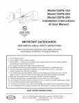
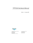
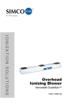
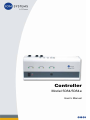
Controller
Model 5084/5084e
User’s Manual
About ION Systems
ION Systems develops, manufactures, and markets system
solutions to manage electrostatic charge. As the world's largest
provider of electrostatics management products and services, ION
improves its customers' business results by providing a total
solution to their electrostatic discharge and electromagnetic
interference challenges. ION Systems is a wholly-owned subsidiary
of Illinois Tool Works (ITW), and is located in Alameda, California.
For more information about ION Systems visit www.ion.com or call
800-367-2452. ION Systems is ISO 9001 and ANSI ESD S20.20.
© 2010 ION Systems, Inc.
19-5084-M-01 Rev 1
Contents
1 Description .......................................................................... 1
1.1 Controller Model 5084(e) ......................................................................... 2
1.2 Connectors, Controls, and Indicators....................................................... 3
1.3 Handheld Terminal................................................................................... 6
1.4 Power Requirements ............................................................................... 7
2 Installation ........................................................................... 9
2.1 Unpacking and Inspection...................................................................... 10
2.2 Controller Mounting................................................................................ 11
2.3 Controller Wiring .................................................................................... 12
2.4 Junction Box Wiring ............................................................................... 14
3 Setup & Operation............................................................. 15
3.1 Local Controller Setup ........................................................................... 16
3.2 Handheld Terminal Menus..................................................................... 19
3.3 Alarm Conditions.................................................................................... 23
3.4 Status Output Connector ....................................................................... 24
4 Maintenance ...................................................................... 25
4.1 Fuse Replacement................................................................................. 26
4.2 Adjustment............................................................................................. 27
5 Specifications.................................................................... 29
6 Warranty & Service ........................................................... 31
19-5084-M-01 Rev 1
1
Description
1.1 Controller Model 5084(e)
1.2 Connectors, Controls, and Indicators
1.3 Handheld Terminal
1.4 Power Requirements
19-5084-M-01 Rev 1
1
1.1 Controller Model 5084(e)
The Controller Model 5084(e) sets the operating parameters and
powers up to eighty ceiling emitters or AeroBars and can adjust on
and off parameters of up to 10 seconds for sequenced bipolar
operation. Timing and output can be programmed through the
Handheld Input Module Model 5080.
Two different versions of the 5084 Controller available from ION
Systems: the standard 5084 and the enhanced 5084e. Throughout
this manual, the different controller versions are referenced as
follows:
• 5084 applies to the standard (non-enhanced) model
• 5084e applies to the enhanced model
• 5084(e) applies to both the standard and enhanced models
19-5084-M-01 Rev 1
2
1.2 Connectors, Controls, and
Indicators
Front Panel Connections
Item
Function
Positive timing on
LED is lit during the on time of the positive (+) power cycle
Positive timing off
LED is lit during the off time of the positive (+) power cycle
Negative timing on
LED is lit during the on time of the negative (-) power cycle
Negative timing off
LED is lit during the off time of the negative (-) power cycle
Reset switch
Rockerswitch that resets the alarm indicators. This switch does not
affect the operation of the emitter alarm indicators.
Handheld Terminal Input
Connector
Modular connector for attaching the handheld terminal input cable
to the 5084(e) Controller
Table 1. Front Panel Connections
Figure 1. Controller Front Panel
19-5084-M-01 Rev 1
3
Top Panel Connections
Item
Function
Emitter output connectors
(J11 and J12)
Supply power to emitters:
Pin 1 - Ground
Pin 2 - Emitter Logic Control Line (±10V)
Pin 3 - Emitter Alarm line (+5V)
Pin 4 - 24 VAC
Status output connector
(J100)
Alarm status output control:
Pin 1 - Relay Output: Normally Open
4-20 mA Output: (-)
Pin 2 - Relay Output: Common
4-20 mA Output: (+)
Pin 3 - Relay Output: Normally Closed
4-20 mA Output: N/A
Fuses (3)
Control - 1/4 Amp. Type 5x20 mm Normal Blow
Alarm - 1/4 Amp. Type 5x20 mm Normal Blow
24 VAC - 3.15 Amp. Type 5x20 mm Slow Blow
Table 2. Top Panel Connections
Figure 2. Controller Top Panel
19-5084-M-01 Rev 1
4
Bottom Panel Connections
Item
Function
Power switch
Rocker switch on the power entry module to turn on/off power to the Controller
Fuse drawer
Requires two 2 Amp. Type 5x20 mm Slow Blow fuses
Table 3. Bottom Panel Connections
Figure 3. Controller Bottom Panel
19-5084-M-01 Rev 1
5
1.3 Handheld Terminal
The Handheld Terminal Model 5080 provides direct access to the
internal processor in the Controller.
The cursor on the Handheld Terminal displays itself as a flashing “o”
on top of the character where it is positioned. When you first enter
a screen, the cursor will be positioned in the first changeable field
location at the farthest to the left of the display. The cursor can be
moved across the screen by using the right (>) or left (<) arrow keys.
When you key in new values, the cursor automatically moves to the
next position to the right.
The non-operational emitter's Alarm LED will be on.
Figure 4. 5080 Handheld Terminal
The Handheld Terminal allows initial Controller setup, monitors the
Controller while in operation, and provides added security. When
the Handheld Terminal is disconnected from the Controller none of
the operational parameters can be altered.
19-5084-M-01 Rev 1
6
1.4 Power Requirements
Caution:
The use of improper input voltage may result in damage to the
unit. Verify the input voltage setting on the fuse drawer before
applying power to the unit.
For safety, the use of extension cords is not recommended.
The 5084(e) Controller must be installed within 6 feet of a properly
grounded receptacle. If no such receptacle exists, one must be
installed following the applicable building and National Electrical
Code requirements.
To reduce the risk of electric shock, this equipment has a grounding
type plug that has a third (grounding) pin. This plug will only fit into
a grounding type power outlet. Do not alter the plug in any way.
The 5084(e) Controller has a variable power input setting
depending on how the fuse drawer on the end panel is installed. The
fuse drawer is located above the power plug connector on the
bottom of the controller.
Before inserting the power plug connector, verify that the correct
power setting is displayed in the fuse drawer window. By default, the
fuse drawer is set to 230V. If the setting is not correct, slide out the
fuse drawer and reset it so that the proper setting is displayed in the
window.
19-5084-M-01 Rev 1
7
19-5084-M-01 Rev 1
8
2
Installation
2.1 Unpacking and Inspection
2.2 Controller Mounting
2.3 Controller Wiring
2.4 Junction Box Wiring
19-5084-M-01 Rev 1
9
2.1 Unpacking and Inspection
Upon receipt of this system, inspect all packages and report any
visible damage directly to the shipper. As the system components
are unpacked, inspect each one carefully for any physical damage
that may have occurred during the shipping process. Do not attempt
to install or apply power to any damaged equipment. If your system
is to be installed by ION Systems personnel, they will perform this
incoming inspection.
19-5084-M-01 Rev 1
10
2.2 Controller Mounting
The 5084(e) Controller is supplied in a wall mount package. The
rear panel of the controller has two key hole cutouts 12 inches (305
mm) apart, center to center, for mounting purposes. The wall
material will determine the style of mounting screw to be used. For
safety considerations, the mounting system used should be able to
support approximately four times the weight of the controller (10 lb
x 4 equals 40 lb).
Examples:
• Single thickness sheet metal wall (approximately 3/64 inches
thick) -- use #12 x 3/4 inch sheet metal screws.
• Sheet metal faced wall with 1/4inch thick metal honeycomb
center -- use #12 sheet metal screws through entire wall
thickness.
• Double wall sheet rock wall -- use 1/4 inch molly bolts.
• Install the mounting screws to the proper depth and place the
5084(e) Controller in position.
19-5084-M-01 Rev 1
11
2.3 Controller Wiring
A number of different wiring methods may be used with the 5000
Series Ionization System. The method used will usually depend on
facilities requirements. The principle method involves the use of 4conductor #22 AWG round cable between the 5084(e) Controller
and a number of junction boxes. From the junction boxes, emitters
are connected using 4-conductor #26 AWG flat style cable and
modular connectors.
Refer to Figures 5 and 6 when wiring up the controller:
Figure 5. System Wiring Diagram
19-5084-M-01 Rev 1
12
Figure 6. Emitter Interconnect Cable
19-5084-M-01 Rev 1
13
2.4 Junction Box Wiring
The figure below shows the wiring detail for a modular cable
junction box. The cable going to the Controller is a 4 conductor
cable that is terminated to an AMP Industries CPC connector.
When connecting the spade lugs to the junction box screw
terminals, care should be taken to insure none of the lugs are
shorted together before installing the cover on the junction box. Also
note that the white wire from the Controller is connected to the
yellow terminal on the junction box. If present, the White and Blue
terminals in the junction box have No Connections (NC). (Note that
not all junction boxes have blue and white terminals).
Figure 7. Junction Box
19-5084-M-01 Rev 1
14
3
Setup & Operation
3.1 Local Controller Setup
3.2 Handheld Terminal Menus
3.3 Alarm Conditions
3.3 Alarm Conditions
3.4 Status Output Connector
19-5084-M-01 Rev 1
15
3.1 Local Controller Setup
The 5084(e) Controller parameters are set using the Handheld
Terminal. The ionization system may be composed of one to a
maximum of 32 ionization zones, each controlled by a single
5084(e) Controller. Each Controller can control from one to a
maximum of eighty emitters.
The 5084(e) Controller switches the Positive and Negative Emitters
on and off according to the time setting in the Positive / Negative
Emitter menu. Alarm conditions occur when there is an emitter
failure (Model 5084e only).
The Handheld Terminal can be connected or disconnected to or
from the Controller with power on.
After the Handheld Terminal is connected to the Controller,
powered up and initialized, the opening menu will appear. By
pressing the appropriate function keys (see Keys and Functions
section), the desired menus may be selected for viewing.
Handheld Terminal Keys and Functions Keys
The Handheld Terminal provides a set of thirty keys and a 4 line
LCD screen display. The keys enable the user to input operational
data, initiate Controller menus and to audit status conditions. There
are three function keys (F1, F2, F3), two on / off keys, eleven
numeric key pad keys, dedicated function keys (Status, Password,
Positive Emitter, Negative Emitter, Alarm Delay), an Escape key
(Esc), four cursor keys and an Enter key.
The following list defines the functions of each of these keys (see
Figure 4 Handheld Terminal):
19-5084-M-01 Rev 1
16
Function Keys
• F1 (not used at present)
• F2 (not used at present)
• F3 used for reinitialization of stored operating parameters.
Reinitialization occurs when F3 is the first key selected during
power up.
Caution:
Using the F3 key to reinitialize the Controller will result in the
loss of all settings made during calibration. The Controller will
default to 5084 non-enhanced operation.
On / Off Keys
• On: Turns a function on when selected.
• Off: Turns a function off when selected.
Numeric Key Pad
• Zero thru nine and “.” (decimal point)
Dedicated Function Keys
• Status: Initiates Status Menu.
• Password: Initiates Password Menu.
• Positive Emitter: Initiates Positive Emitter Menu for entering
Positive on and off Times and Positive Output.
• Negative Emitter: Initiates Negative Emitter Menu for entering
Negative on and off Times and Negative Output.
• Alarm Delay: Initiates Alarm Delay menu for entering the
number of cycles of continuous alarm line active before
qualifying the alarm condition as a real alarm.
• Cursor Keys: (^,V,<,>) used to sequence through menus.
• Esc Key: Used to cancel an operation.
• Enter Key: Used to enter data.
19-5084-M-01 Rev 1
17
Functions
When you change and enter a value or condition, that change is
made immediately. There is no additional save operation.
When a numeric value such as a password, time or percent is
entered, the new value is keyed directly over the existing value.
The Enter key must then be pressed to send the new value to the
Controller. If you leave a screen or window without pressing the
Enter key, the original value is maintained.
However, when you use a Condition key that turns a function on or
off, you need only press the On or Off key on the Handheld
Terminal. You do not need to press the Enter key.
19-5084-M-01 Rev 1
18
3.2 Handheld Terminal Menus
Password
The following items are displayed by
pressing the Password button.
To change any operating parameters
for the 5084(e), the password key must
be pressed and the proper password
entered. The 5084(e) recognizes two
types of passwords, the Operator
Password and the Upgrade/Master
Password. For information on the Upgrade/Master Password,
please contact ION Systems ([email protected]).
To input the Operator Password:
1. Press the Password key.
The symbol “>” preceding a small flashing square is displayed.
2. Enter the Operator Password 1 2 3 on the numeric keypad
followed by the Enter key. (The numbers will not appear
onscreen.)
If the password is correct, the Handheld Terminal will display
the message: “>Accepted”.
3. The "^" and "v" keys can be used to scroll to the other Password
menu items, “Mode Selection” and “Zone number” which are
described below.
Mode Selection
With the proper upgrade password, the 5084E/PD mode can be
selected to enable the alarm functions of the Controller. To change
the Controller mode, press the Password key and use the V key to
move to “Mode Selection.” Use the > key to select 5084 or 5084e.
19-5084-M-01 Rev 1
19
Zone Number
The zone number parameter is not applicable with this equipment.
Status
Display the following items by
pressing the Status key:
Emitter Failure (Model 5084e only):
The Emitter Failure indication will
display either “yes” or “no” based on
the Emitter’s operational condition. If
“yes” is displayed, one or more of the
emitters controlled by the present
Controller has failed. As the sensing
line of all emitters is daisy-chained,
you must determine the location of the
failed emitter by a visual inspection of
the emitter installation.
When you have completed your entry
and pressed the Enter key, the cursor
will move back to the first field
location. The value displayed should
be the value you previously input.
This indicates that the value was valid
and accepted. To change the value, enter new values and press the
Enter key.
Alarm Function (Model 5084e only): Setting to off overrides the
emitter failure Alarm condition.
Audible Alarm (Model 5084e only): Controls the Alarm beeper.
When set to off, the beeper will not sound when an alarm condition
exists. The visual Alarm LED will still indicate an alarm condition.
Auto Shutoff (Model 5084e only): When set to on, all emitters will
be shut down (turned off) in the event of any emitter failure. If set to
off, the emitters will continue to operate, but the Alarm will still
function. (ION Systems recommends setting to off).
19-5084-M-01 Rev 1
20
Emitter Count: Indicates how many emitters are connected to the
Controller. This value must be entered manually and has no affect
on Controller operation.
Ver / PROM SN: Identifies the Controller software version and
PROM serial number.
EPROM/RAM ERROR: Will indicate “yes” if an EPROM or RAM
error exists.
Positive Emitter and Negative Emitter
Two dedicated function keys provide access to the menus that set
desired emitter timing and power output:
POS EMITTER and NEG EMITTER: Time on and time off as well
as Pos Output (in %) and Neg Output (in %).
The time range of the Positive /
Negative on time is 0.1 to 9.9 sec.
The time range of the Positive /
Negative off time is 0.0 to 9.9 sec.
The power range of the Output Level
is 0 to 100%.
Alarm Delay
The Alarm Delay can be set between
0 to 128. The number of delays is
used to count the number of
completed pos/on_off and neg/
on_off cycles wherein the Alarm line
is continuously active. Alarm flags
will be raised depending on the
mode set for the Controller.
19-5084-M-01 Rev 1
21
System Timing
The table below indicates suggested initial settings for the timing
and output levels of the 5000 Series Ionization System. Values are
set using the 5080 Handheld Terminal. These values were obtained
from measurements obtained in ION Systems test facility. Values
listed are for both laminar and non-laminar airflow conditions. The
airflow was measured at workbench level, a height of 36 inch (91
cm).
Airflow
On Time
Off Time
Output Level
50 fpm laminar
2.50
1.50
50.00
100 fpm laminar
1.50
1.00
25.00
10 fpm, non laminar
4.00
2.50
75.00
25 fpm, non laminar
3.50
2.00
55.00
Table 4. Airflow Settings
Note:
These values will vary according to the actual environment.
19-5084-M-01 Rev 1
22
3.3 Alarm Conditions
The 5084(e) Controller signals an emitter alarm condition by
flashing the red front panel alarm LED. If the audible alarm is set to
on, it will sound. Note that an alarm condition is not signalled at the
controller until an emitter alarm has been sustained for the number
of on/off cycles defined by the Alarm Delay setting.
An emitter alarm indicates that one or more emitters have failed to
function or that a wiring problem exists. The emitter in alarm
condition will be identified by its alarm light (center LED).
19-5084-M-01 Rev 1
23
3.4 Status Output Connector
The alarm status from the Status Output Connector (J100) is as
shown in the table below.
Alarm Active
Alarm Inactive
Brownout
Current Loop
20 mA
4 mA
0 mA
Relay Contact (J1001-J1002)
closed
open
closed
Relay Contact (J1002-J1003)
open
closed
open
Table 5. Alarm Status Conditions
For additional information on the Status Output Connector see 1.2
Connectors, Controls, and Indicators section.
19-5084-M-01 Rev 1
24
4
Maintenance
4.1 Fuse Replacement
4.2 Adjustment
There are no user-serviceable parts inside this Controller. Any
unauthorized service will void the warranty and may result in
additional repair charges.
Caution:
These instructions are for use by qualified maintenance
personnel only. To avoid personal injury or damage to the
equipment, do not perform any maintenance other than that
contained in these instructions.
19-5084-M-01 Rev 1
25
4.1 Fuse Replacement
Fuse Type Location(s)
ION Systems
P/N
Schurter
P/N
1/4 amp 5x20 mm Normal Blow Control Line and Alarm Line
28-1445
034.1510
2 amp 5x20 mm Slow Blow 120/240 VAC Line
28-1450
034.3120
3.15 amp 5x20 mm Slow Blow 24 VAC Line
28-1455
034.3122
Table 6. Fuse Replacement Parts
19-5084-M-01 Rev 1
26
4.2 Adjustment
Use a Charged Plate Monitor (CPM) Model 280A (available from
ION Systems), to adjust the 5000 Series’ ionization components.
The test method used to adjust emitters is described in detail in the
ANSI / ESD Standard STM3.1-2000 and the Instruction Manual for
the Model 280A. The test setup is shown in below.
Figure 8. Charged Plate Monitor Test Setup
19-5084-M-01 Rev 1
27
19-5084-M-01 Rev 1
28
5
Specifications
Controller Model 5084
Power
24W + 1W per emitter
Input
100-240 VAC ±10%, 50 or 60 Hz voltage-selectable and fuse-protected
Output
24 VAC, ±10 VDC control signal
Output Signal
-10 to +10 VDC, controls output level for each polarity
Capacity
80 emitters or bars
Timing Control
Ionization on and off cycles for each polarity (0-9.9 seconds)
User Interface
Handheld Terminal Model 5080
Indicators
Power on, alarm, positive/negative emitter on/off, local communication
Dimensions
15L x 4.5D x 6.75H in. (38.1 x 11.4 x 17.1 cm)
Weight
9.25 lb (4.2 kg)
Certifications
Controller Model 5084e (The 5084e meets all the specifications of the 5084)
Alarm
Audible and/or visual (LED) indicates emitter failure; audible alarm is on/
off switchable
Alarm Reset
Switch provided on front panel
User Interface
Handheld Terminal Model 5080 or Facilities Monitoring System
19-5084-M-01 Rev 1
29
19-5084-M-01 Rev 1
30
6
Warranty & Service
ION Systems provides a limited warranty for the Controller Model
5084(e) to be free from defects in material or workmanship for a
period of two years from the date of receipt or installation.
ION Systems liability under this warranty is limited to replacing or
repairing any unit, returned by the purchaser, which has not been
subjected to misuse, neglect, repair, alteration, or accident. In no
event shall ION Systems be liable for collateral or consequential
damages.
To obtain service under this warranty, please contact ION Systems
Technical Support ([email protected] or 510-217-0470).
19-5084-M-01 Rev 1
31
19-5084-M-01 Rev 1
32
Notes
19-5084-M-01 Rev 1
33
Notes
19-5084-M-01 Rev 1
34
1750 North Loop Road
Alameda, CA USA 94502
Tel: 510-217-0600
Fax: 510-217-0484
Toll free: 800-367-2452
Sales services: 510-217-0460
Tech support: 510-217-0470
[email protected]
[email protected]
[email protected]
[email protected]
www.ion.com
19-5084-M-01 Rev 1