1
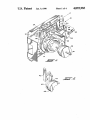
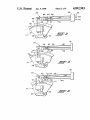
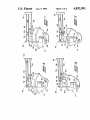
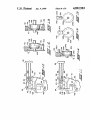
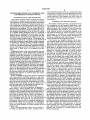
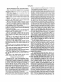
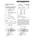
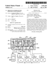
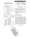
United States Patent [191
[11] Patent Number:
4,892,983
Bogda et a1.
[45]
Date of Patent:
Jan. 9, 1990
[54] PROGRAMMER/TIMER WITH COMBINED
LINE AND PROGRAM FUNCTION SWITCH
[75] Inventors: Richard C. Bogda, Elmhurst; George
D. Georgacakis, Skokie, both of Ill.
Primary Examiner-J, R. Scott
Attorney, Agent, or Firm—-R. A. Johnston
[57]
ABSTRACT
A combination programmer and line switch for an ap
Eaton Corporation, Cleveland, Ohio
[21] Appl. No.: 281,572
Dec. 8, 1988
[22] Filed:
motor connected for advancing the cam. An upper line
power contact blade is moved between high and low
positions by a manual actuator. A lower contact blade is
[51] Int. 01.4
[52] US. Cl.
H01H 43/00
200/38 R; 200/38 A;
maintained stationary and is adapted for connection to
certain appliance load functions. An intermediate pro
200/ 38 B; 200/38 C
200/38 R, 38 A, 38 F,
gram contact blade series connected to the timing
motor has a follower biased against the program cam
200/38 FA, 38 PB, 38 B, 33 BA, 38 C, 38 CA
and is adapted for connection to all appliance functions.
[73] Assignee:
[58] Field of Search
[56]
References Cited
pliance having a rotary program cam and a timing
with-the upper contact
the high position, the motor
circuit is open for all positions of the program and in the
us’ PATENT DOCUMENTS
3,431,372
4/1969
Obermann
low position the timing motor is energized. Alterna
.
tively, the program cam may include a line contact
3,752,944 2/1975
3,866,002
8/1973 Underwood
Cartier etal. etal
switch override to maintain the intermedaite blade in
contact with the upper blade for both positions of the
4,413,16411/1983
4,497,985 2/1985
manual actuator.
Obermann et a1. .
Courter m1.
..
4,497,986 2/1985 Zink etal
4,560,846 12/1985 Klopp et al. ..
7 Claims, 4 Drawing Sheets
US. Patent
Jan. 9, 1990
Sheet 1 of4
4,892,983
US. Patent
Jan. 9, 1990
Sheet 4 of4
4,892,983
1
‘4,892,983
2
cam operated program switch in a programmer/timer
PROGRAMMER/TIMER WITH COMBINED LINE
-
AND PROGRAM FUNCI‘ION SWITCH
BACKGROUND OF THE INVENTION
The present invention relates to electrical program
mer/timers for appliances and particularly for house
hold appliances such as washing machines, dishwashers
and clothes dryers having user selected program inter
vals. Appliances of this type typically have a knob or
dial rotated by the user for selection of the length of the
having rotary cam drum for actuating program function
switches and to maintain power to the timing motor for
certain positions of the program cam drum when the
5 line switch is manually opened with the cam drum in
such position.
SUMMARY OF THE INVENTION
The present invention provides a programmer/timer
for an appliance such as household dishwashers, wash
ing machines and clothes dryers and has a rotary pro
gram cam drum with a plurality of cam followers dis
appliance service program. The user rotates the dial to
the selected dial position or mark for positioning a rotat
able program cam operative to be advanced or rotated
by a suitable timing mechanism such as a motorized
chine function switch in a prescribed sequence as the
cam drum is advanced by rotary movement. The cam
speed reducer or periodically advanced pawl driving a
advancement is provided by a synchronous timing
toothed ratchet connected to the program cam and
motor connected via a speed reducer mechanism for
indexing the cam with each stroke of the pawl for time
driving an oscillating pawl which indexes the ratchet
posed thereabout each operative for actuating a ma
out of the selected program interval. The program cam
wheel connected to the program cam drum.
is typically contacted by a plurality of cam followers 0 A line power and program function switch has a
positioned thereabout for providing a desired sequence
user-actuated axially moved cam member for contact
of operation to electrical function switches connected
to each of the cam followers. The switches typically
provide for the desired individual appliance functions
such as controlling an electric water inlet valve, a water
drain pump or drain valve, or an agitation and spin
motor.
Programmer/timers of the above-described type are
typically driven by a small subfractional horsepower
synchronous timing motor which is connected to the
appliance power line connector via a line switch. In
some household appliance designs, it has been desired to
provide actuation of the appliance line power switch by
providing an axial movement to the program knob or
dial for actuation of the line switch. Where space is at a
ing a slider member which is moved radially for actuat
ing an upper line power switch contact blade which is
disposed as the uppermost blade in a stack of at least
three blades. A program switch contact blade which is
the lowest of the stack has a stationary position and is
adapted for electrical connection to certain machine
functions. An intermediate switch contact blade has a
cam follower provided thereon and is moved in re
sponse to the program cam for making and breaking a
circuit with the upper line contact blade when a line
switch actuator cam member is axially moved between
the “ON” position and the “OFF” position. The inter
mediate contact blade is operative to make and break a
premium for packaging the programmer/timer in the
appliance control panel housing, the size of the program
circuit connection with the lower program blade only
thereby. It has therefore been desired to integrate the
line function switch with the switches actuated by the
contact blade to maintain line power to the timing '
in response to movement of the program cam. When the
line switch actuator cam is positioned to the “ON”
cam drum is limited, which in turn limits the number
position, the upper contact blade moves downward
and size of cam actuated function or program switches
that can be disposed about the cam drum for actuation 40 under self-bias to make contact with the intermediate
motor and certain machine program functions for all
positions of the program cam. In an alternative embodi
program cam followers to conserve space and reduce
ment, the program cam is provided with suf?cient lift in
manufacturing cost.
Where the appliance line power switch is combined 45 certain positions to maintain the intermediate contact
blade against the line power contact blade when the line
with cam actuated switching functions, it has been
switch actuator is in the “OFF” position, for maintain
found difficult to provide for separate user-actuation of
ing power to the timing motor for said certain positions
the line power switch to retain user control of the appli
of the program cam to provide continued timing motor
ance, and yet also provide for continuing power to the
operation for resetting the cam when the line power
timing motor for advancing the cam to a desired posi
switch is opened by the appliance user to prevent subse
tion for restart after all other appliance functions have
quent restart with the cam in an undesired position.
been disconnected by the power line switch.
The present invention thus provides a low cost com
It is known to provide an appliance programmer/
pact programmer/timer for a household appliance and
timer having a rotary program cam for actuating a
employs a rotary program cam with a line power switch
plurality of function switches wherein the line switch is
combined with one of the program switches to provide
combined with a program switch and the line switch is
for maintaining power to the cam advance motor when
actuated by axial movement of the knob shaft for mov
the program switches are open. The present invention
ing a slider to actuate the line switch. An example of
thus provides for line switch and program function
such is described in US. Pat. No. 3,431,372 in the name
of G. Obermann and in US. Pat. No. 4,497,985 in the 60 switching in a single combined switch start actuated by
a single cam track. In the present invention the user also
name of Courter etal. However, the aforementioned.
programmer/timers having a combined program and
provides line switch actuation by axial movement of a
line function switch do not provide for maintaining
line switch actuator cam connected to the rotary selec
power to the timing motor irrespective of the position
tor knob. Alternatively, axial movement of the line
of the line switch actuator for certain positions of the 65 switch actuator cam may be affected by an auxilliary
program cam.
cam which follows a stationery projection when the
Thus, it has been desired to find a way or means of
program cam is rotated to a certain position by the
providing an appliance line switch combined with a
advance mechanism.
3
4,892,983
4
manner well known in the art, the details of which have
BRIEF DESCRIPTION OF THE DRAWINGS
been omitted for the sake of brevity.
Deck plate 12 has mounted thereon an insulator block
- FIG. 1 is a somewhat perspective of the program
32 which has molded therein and extending outwardly
thereform in spaced generally parallel cantilevered rela
mer/timer of the present invention with portions of the
housing removed;
tionship a plurality of stacked switch contact blades
comprising a combination line and program switch
assembly indicated generally at 34. The combination
FIG. 2 is an enlarged view of a portion of the line
switch actuator of FIG. 1;
FIG. 3 is a front view of the combined line/program
switch of FIG. 1 with the line switch actuator in the
“OFF” position and the switches in the open circuit
switch has an upper contact blade 36 which extends the
furthest distance from block 32 and which has a termi
nal portion 38 extending through the block 32 and out
wardly therefrom for electrical connection to one side
of a power line. The line switch contact blade 36 has
condition;
FIG. 4 is a view similar to FIG. 3 with the line switch
actuator in the “ON” position, the line switch closed
and the program switch open circuit;
provided on the lower face thereof a suitable button
contact 40 which is adapted for making and breaking a
FIG. 5 is a view similar to FIG. 4 with the program
cam rotated to a position closing the program switch;
FIG. 6 is a view similar to FIG. 3 and shows the line
cent the lower face of the line switch contact blade 36
switch actuator in the “OFF” position with the pro
near its free end is a line switch actuator 42 which is
gram maintaining the line switch closed;
suitably mounted on deck plate 12 for sliding movement
circuit upon movement of the blade 36. Disposed adja
FIG. 7 is a view similar to FIG. 6 with the line switch 20 in the vertical direction. Line switch actuator 42 has an
actuator in the “ON” position and the cam maintaining
inclined “cam surface 44 provided thereon which
contacts a corresponding surface 48 provided on an
the line switch closed;
FIG. 8 is a view similar to FIG. 7 with the line switch
axially movable cam member 46. Cam member 46 has a
actuator in the “ON” position and the cam rotated to a
shaft extending therefrom which is received in cam 14
position closing the program switch;
25
for axially sliding movement therein by the appliance
FIG. 9 is a view similar to FIG. 8 with the program
cam in the same position as FIG. 8 but with the line
user. Axial movement of cam member 46 is effective to
cause movement of line switch actuator 42 from the
switch actuator in the “OFF” position opening the line
position shown in solid outline in FIG. 2 to the position
shown in dashed outline. It will be understood that shaft
49 although axially moveable is engaged with cam drum
switch;
FIG. 10 is a view similar to FIG. 9 with the line
switch actuator in the “OFF” position and the cam
rotated to a position maintaining both line and program
switches in the open circuit condition;
FIG. 11 is a view similar to FIG. 10 with the cam
positioned in the same position as FIG. 10 but with the
line switch actuator the “ON” position closing the line
switch;
FIG. 12 is a view of an alternate embodiment of the
line switch actuator cam illustrated in the “OFF” posi~
tion;
FIG. 13 is a view similar to FIG. 12 showing the line
switch actuator in the “ON” position;
FIG. 14 is a view similar to FIG. 12 showing another
embodiment of the line switch actuator cam;
FIG. 15 is a right-hand view of the embodiment of 45
FIG. 14 with the line actuator cam in the “ON” posi
tion; and
FIG. 16 is a view similar to FIG. 15 with the line
switch actuator cam in the “OFF” position.
DETAILED DESCRIPTION
Referring to FIGS. 1 and 2, the programmer/timer is
indicated generally at 10 and has a housing or deck plate
14 for rotation therewith by any suitable means such as
a clutch, ?ats on shaft 49 (not shown) or other tech
nique well known in the art. '
A lower program contact blade 50 is mounted in and '
extends from insulator block 32 in cantilever arrange
ment with the free end thereof having a follower 52
thereon for contacting a level surface 15 of the cam
drum for stationary location with respect to the drum
surface as a datum from which the cam track 16 is lo
cated. The program blade 50 has an electrical contact
54 disposed on the upper surface thereof with reference
to lower program contact blade 50 has a connector
portion 52 thereof extending through insulator block 32
and adapted for electrical connection to various desired
appliance load functions.
An intermediate program blade 58 is disposed be
tween upper blade 36 and the lower blade 50, the inter
mediate blade extending in cantilever from insulator
block 32 in spaced generally parallel relationship with
blades 36 and 50. Intermediate blade 58 has a cam fol
lower 60 provided at the free end thereof which fol
lower is self-biased by the blade 58 to ride on cam track
16. The intermediate blade 58 has an upper contact 62
12 upon which is mounted a program cam 14 journaled
which is aligned vertically with the contact 40 on the
on housing 12 and which has thereon a cam track 16 and 55 line switch contact blade; and, blade 58 has a lower
an advance ratchet wheel having teeth 18 thereon for
contact 64 disposed on the undersurface thereof and
rotation with the cam 14. Auxiliary support bracket
aligned with the contact 54 on the lower program blade.
with arms 20, 22 is attached to the deck plate 12 by
An electrical connector portion 68 of blade 58 extends
suitable means as for example, twist-tabs (not shown). A
through block 32 and externally thereof for connection
suitable gear reduction indicated generally at 24 is 60 to motor lead 28 as indicated in FIG. 1 by dashed line.
driven by a timing motor 26 mounted on the exterior of
Rotation of the cam 14 causes the follower 60 to rise
bracket arm 20. Motor 26 has its shaft engaging the gear
and fall in accordance with the contour of the cam track
box 24 through bracket arm 20 and the motor 26 has a
16 thereby raising and lowering intermediate blade 58
pair of electrical leads 28, 30 adapted for attachment to
for moving contact 64 between an open and closed
a line switch as will hereinafter be described.
65 position with respect to the lower contact 54 for making
The ratchet wheel teeth 18 are driven by an oscillat
and breaking a circuit between the connector terminals
ing pawl (not shown) which interconnects the gear box
24 with the ratchet teeth for indexing the cam 14 in a
52, 68. It will be understood that upon closure of the
contact pair 62, 40 between the intermediate blade and
5
4,892,983
6
the upper line power contact blade, line power is con
maintained in the same position as shown in FIG. 6;
nected to motor 26.
however, the line switch actuator 42 has been dropped
‘ Referring to FIGS. 1 through 5, the cam drum 14 is
to the lower or “ON” position by moving the member
shown in a position wherein the cam follower 60 is
46 axially until the cam surface 44 has dropped onto the
raised to ride on cam track 16 wherein the intermediate
cam surface 48 (see FIG. 2). In the condition of FIG. 7,
blade 58 is raised and maintained in a position to open
switch 34 has the line power contact blade 36 biased
the contact set 54, 64 between the intermediate blade 58
downwardly to close the contact sets 40, 62 maintaining
and the lower blade 50, thus breaking circuit connec
power to the timing motor. With reference to FIGS. 6
tions for the selected appliance functions.
and 7 it will be seen that irrespective of the position, e. g.
In FIG. 3, the line switch actuator 42 is shown in the 10 “OFF” or “ON”, of line switch actuators 46, 42
raised or uppermost position limit of its travel wherein
contacts 40, 62 are closed and power to the timing
the follower 44 is riding on the outer diameter 46 of the
motor is continued; whereas, the lower set of contacts
actuator member. In the position shown in FIG. 3, the
64, 54 is broken.
line switch actuator 42 has raised the upper line power
Referring to FIG. 8, the line switch actuator member
contact blade 36 to a position wherein contacts 40, 62
42 is maintained in the lower position as described with
are broken thereby cutting off line power to the timing
respect to FIG. 7; however, the cam 14 has been rotated
motor 26 and all other appliance functions. In the condi
until the cam follower 60 is disposed above portion 120
tion of switch combinations 34 shown in FIG. 3, the
of the cam track. In the cam track position shown in
cam drum 14 is immobilized because the timing motor is
FIG. 8, blade 58 has dropped to close the lower contact
inactivated.
set 64, 54 for providing power to the selected appliance
Referring to FIG. 4, the switch combination 34 is
functions, while the upper contact set 62, 40 is main
changed although the cam with same position of FIG. 3
tained closed for continuing power to the timing motor.
is illustrated, but with the line switch actuator 42
Referring to FIG. 9, the cam 14 and track portion 120
dropped to the lower position wherein the camming
are maintained in the same position as illustrated in FIG.
surface 44 thereon is released from the outer diameter 25 8, the lower contact set 64, 54 is maintained closed;
46 of the axially movable actuator member to ride on
however, the line switch actuators 42, 46 have been
the cam surface 48 (FIG. 2). In the position shown in
FIG. 4, the line switch actuator has permitted the upper
contact blade 36 to drop under its self-bias until the
contact set 40, 62 has closed thereby providing current
to flow through contact blade 58 and its connector 68 to
the timing motor 26 for continuing advancement of cam
14. In the position shown in FIG. 4, the line switch
actuator members 42 and 46 are considered to be in the
“ON” position (shown in solid outline in FIG. 2).
moved to the “OFF” position and raising "contact blade
36 and no power flows through the contacts 54, 64
because line power has been broken by the upper set of
contacts.
Referring to FIG. 10, the cam 14 has been rotated to
a position wherein the intermediate level 118 of cam
track is lifting the cam follower 60 and intermediate
contact blade 58 to a open switch condition. The line
switch actuator 42 has been moved to the raised or
Referring to FIG. 5, switch combination 34 is shown
“OFF” position wherein blade 36 has been raised to
break contacts 40, 62.
neath follower 60 which has dropped into the depres
Referring to FIG. 11, the program cam track has
sion 56 formed in the cam track 16. In the position
been maintained in the same position as in FIG. 10;
shown in FIG. 5, the line switch actuator 42 is main 40 however, the line switch actuator member 42 has been
tained in the “ON” position (shown in solid outline in
dropped by axial movement of the member 46 to cause
FIG. 2) as in FIG. 4; and, the contact blade 58 has
cam surface 44 to drop onto the cam 48 as shown in
dropped to close the lower set of contacts 64, 54 with
solid outline. With the line switch actuator in the posi
and the line power blade self bias maintaining the
tion shown in FIG. 11, the self-bias of blade 36 has
contact pair 40, 62 closed. In the switch position shown 45 closed the contacts 40, 62 while the lower contact set is
is FIG. 5 both sets of contacts are closed and power is
maintained broken for preventing current ?ow to the
provided to the machine functions through the lower
appliance functions. Thus, it will be seen that the inter
set of contacts and to the timing motors through the
mediate cam track surface 118 is operative to effect
upper set of contacts.
opening and closing of the circuit to the timing motor.
Referring to FIGS. 6-11, an alternative embodiment
Referring to FIGS. 12 and 13, an alternative version
in a condition wherein cam track 16 is no longer be
of the programmer cam track 116 is illustrated as having
an intermediate step down level 118 and a lower level
120. With reference to FIG. 6, the line switch actuator
of the line switch actuator is shown wherein the cam
member 146 has a conical or chamfered auxilliary cam
ming surface 148 thereon which contacts the vertical
members 46, 42 are shown in the “OFF” position
slider member 42 for actuating the upper contact blade
wherein the cam surface 44 on the actuator 42 is riding
36. The cam member 146 is supported by shaft 149
on the large diameter 46 of the axially movable actuator
which is journaled at one end in the deck plate 12 and
member. In the condition of switch combination 34
has the opposite end shown truncated in FIGS. 12 and
shown in FIG. 6, cam track surface 116 has raised the
13, but actually extending outwardly for user actuation
cam follower 60 closing contacts 62 40 thereby main
via a knob (not shown).
taining power to the timing motor and the lower 60 Cam member 146 has provided thereon an auxiliary
contact set 64, 54 is broken, thereby terminating current
helical cam surface 151 which contacts a tab or lug 153
?ow to the appliance program functions. Thus, it will
formed on the deck plate for automatically providing
be seen that in the switch condition shown in FIG. 6 the
leftward axial movement of the cam member 146 upon
cam track 116 maintains power to the timing motor
rotation of the member 146 by shaft 149 due to the
despite the user movement of the line actuator to the 65 rotational coupling of the shaft 149 with cam drum 14.
“OFF” position.
With reference to FIG. 12, the auxiliary cam 151 is
Referring to FIG. 7, .a changed condition of switch
shown in the “ON” position with the cam member 146
combination 34 is shown wherein the cam track 116 is
moved axially rightward by user movement of shaft 149
7
4,892,983
permitting rightward movement for camming slider 42
to be moved vertically downward for enabling moving
8
(b) a program cam mounted for rotary movement on
said housing means;
(c) timing motor means associated with said housing
means and operable upon energization to effect
the contact blade member 36 to move to the position
contacting blade member 58 to close contact 40, 62.
Referring to FIG. 13, cam member 146 has been
rotated by the cam drum 14 approximately one-quarter
said movement of said program cam;
(d) a ?rst movable line switch contact blade mounted
turn counterclockwise, as viewed from the right side in
FIG. 12, to a position where auxiliary cam surface 151
on said housing means for connection to one side of
a power line;
has acted against the end of the lug 153 to cause diago
nal sliding contact between cam surface 148 and surface
(e) actuator means movably mounted on said housing
means and including auxiliary cam means contact
ing a movable member operable upon user manual
44 thereby raising the slider 42 and positioning the line
switch blade 36 in the position breaking the circuit
movement to move said movable member for mov
ing said movable ?rst contact blade between a ?rst
between contacts 40, 62. The version shown in FIGS.
12 and 13 thus incorporates an automatic appliance
(low) and second (high) position;
(i) a stationary contact blade mounted on said hous
shut-off at the end of the program or where the user has
ing means for series connection with certain appli
ance functions;
(g) an active program switch contact blade disposed
manually rotated shaft 149 to position member 146 and
surface 151 to the position shown in FIG. 13.
Referring to FIGS. 14 through 16, a further alterna
on said housing means between said ?rst movable
tive version of the line switch actuator mechanism is
line contact blade and said stationary blade, said
illustrated where a cam member 246 has shaft 249 ex
program switch blade including a cam follower
tending in opposite directions therefrom, with one end
joumaled in plate 12 and the other end in the direction
opposite the plate 12 for user actuation, but shown
truncated. The member 246 has a conical or chamfered
auxiliary cam surface 248 provided on the axial end
contacting said program cam, said program switch
blade series connected with said motor means for
series connection with all of said appliance func
tions, wherein said line contact blade in said high
position prevents energization of said motor for
25
thereof adjacent plate 12 and a lug 251 extending radi
ally outwardly from the outer diameter thereof. The
any position of said cam follower on said program
mer cam and in said ?rst (low) position, maintains
said motor energized for all positions of said cam
line switch actuator slider 142 has provided thereon a
projection 253 which has a generally cylindrical con?g
uration to provide a camming action upon rotation of
the cam member 246 to a position such that the end of
the projection 251 engages the cylindrical surface of the
member 253. Rotation of the member 246 by user rota
tion of shaft 249 one-quarter turn counterclockwise
_ from the FIG. 15 position as shown in FIG. 16 raises
slider 142 to its vertically upward position thereby rais
ing line switch contact blade member 36 to the “OFF”
position.
30
follower on said program cam.
2. The combination defined in claim 1, wherein said
actuator is user movable between a first position lower
ing said line switch blade toward said program cam and
a second position raising said line switch blade further
from said program cam.
3. The combination de?ned in claim 1, wherein said
actuator means includes a cam member movable in an
axial direction with respect to rotation of said program
cam and a second member movable in a radial direction
The present invention thus provides a programmer/
for contacting said line contact blade.
timer for an appliance wherein the line power switch
4. The combination de?ned in claim 1, wherein said
for controlling power to the timer motor for advancing
actuator means is operable to move said line switch
the program cam drum and all of the machine functions
contact blade between a ?rst (low) position to a second
is combined with a program switch for controlling
(high) position, said actuator means operable in said ?rst
selected machine functions in response to cam drum 45 position to maintain said line switch contact blade in
rotation. A user operated actuator permits the appliance
closed circuit contact with said program contact blade
user to selectively open and close the line power switch
energizing said motor means for all positions of the
during operation of the machine program.
program cam and operable in said second position to
The present invention provides for a single switch
maintain said line switch contact blade in open circuit
start which combines line power switching with se 50 position with respect to said active program blade de
lected program switching in response to a follower on a
energizing said motor means for all positions of said
single program cam track. In one embodiment, the pro
program cam.
gram cam maintains power to the timing motor to ad
5. The combination de?ned in claim 1, wherein said
vance the cam when the user opens the line power
actuator means is movable in response to user actuation,
switch with the program cam in certain positions to
between a ?rst (low) position and a second (high) posi
tion, wherein said line switch contact blade in said ?rst
position maintains a closed circuit with said active pro
stop the main appliance functions. Continued rotation
of the cam by the advance mechanism advances the cam
to provide certain function positions desirable for re
start upon the user closing the line power switch.
gram blade for all positions of said cam and a second
(high) position wherein said active blade in said second
Although the present invention has hereinabove been 60 position opens the circuit with said line switch contact
described with respect to the illustrated embodiments, it
will be understood that the invention is capable of modi
blade for certain positions of said program cam, and is in
open circuit with said line switch contact blade for
?cation and variation and is limited only by the follow
other positions of said program cam, said actuator
ing claims.
‘
means in said ?rst (low) position maintains said active
We claim:
65 program contact blade in closed circuit relationship
1. A combination electrical programmer timer and
with said line switch contact blade and said timing
line switch assembly for an appliance comprising:
motor means energized for all positions of said program
(a) housing means;
cam.
9
4,892,983
6. The combination de?ned in claim 1, wherein said
10
program cam is operative in certain selected positions to
maintain said program contact blade in closed circuit
contact with said line contact blade for both of said high
and low positions of said actuator means.
actuator means includes selector cam means operable
drum user rotation to effect movement of said actuator
means between said ?rst (low) and said second (high)
position.
ill
7. The combination de?ned in claim 1, wherein said
10
15
20
25
35
45
55
65
*
*
It
*