1
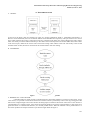
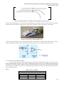
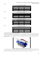
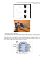
International Journal of Innovative and Emerging Research in Engineering
Volume 2, Issue 2, 2015
Available online at www.ijiere.com
International Journal of Innovative and Emerging
Research in Engineering
e-ISSN: 2394 - 3343
p-ISSN: 2394 - 5494
Wireless Animatronic Hand using Control Glove
Tejashree Dhamapurkar1, Neelakshi Ghag2, Aarti Kamble3, Krutika Bhiwapurkar4,
Prof. Mrs. Shubhada Deshpande5
Padmabhushan Vasantdada Patil Pratishthan’s College Of Engineering, Sion, Mumbai
ABSTRACT:
This paper discusses the design and implementation of a wireless animatronic hand using XBee-S2 and ArduinoUNO board. The main aim of this paper is to highlight mainly the use of wireless communication and it’s
applications by using wireless animatronic hand. The system/ electronic product was implemented using control
glove, micro servo motors, XBee-S2 and Arduino-UNO board having on-board Atmega-328.
Keywords: XBee-S2, Arduino-UNO, XBee shield, flex sensors, micro servo motors.
I. INTRODUCTION
Wireless animatronic hand is basically a robotic hand which is implemented by using a latest wireless technology.
Intension of this product is to help/get involved in many of the industries where human hand is must to complete the
required task; but it may harm human skin or bones. Here, instead of using actual human hand, we can replace it by this
wireless robotic hand. We may allow this robotic hand to complete the same task so that the risk will be avoided and
obviously, required task can be achieved. For example, consider a chemical industry where highly hazardous chemicals
are to be handled every day. In this case, to handle extremely hazardous substances like Allylamine, Bromine chloride,
Methyl isocyanate etc. if we will allow this wireless animatronic hand, it will be safer for everyone. Also this hand can
help paralysis patients who can’t move from the bed. Consider a paralysis patient wants to switch ON the fan; but he can’t
get up from the place where he is and he is alone at his home. In this case, a robotic hand is there, so that by moving a
control glove, he can easily push the switch by using a wireless robotic hand. This paper intends to implement an affordable
electronic product known as wireless animatronic hand based on wireless technology based on XBee-S2 as well as ArduinoUNO board. Arduino-UNO is a microcontroller board which has on-board microcontroller ATmega-328. It has total 14
pins including analog and digital pins. There are 6 PWM(Pulse Width Modulation) output pins on this board. Also, it has
6 analog inputs, a USB connection, a power jack, a 16 MHz ceramic capacitor, an ICSP header and a reset button. The
Arduino-UNO differs from all preceding boards in that it does not use the FTDI USB-to-serial driver chip. Instead, it
features the Atmega16U2 (Atmega8U2 up to version R2) programmed as a USB-to-serial converter; so that this board is
used to make this robotic hand. Basically there are two main parts of this project i.e. transmitter (Control glove) and receiver
(mechanical-electronic robotic hand). Control glove mainly consists of flex sensors. There are total five flex sensors placed
separately on each finger on the glove. Human hand will control another robotic hand; so that it is called as a control glove.
Future efforts would be to make this hand to fly as well as to move from one place to another.
II. BACKGROUND WORK
A flex sensor is a mechanical device that provides a varying amount of resistance when sensor is bent. By passing
particular amount of voltage through a flex sensor into an analog input on Arduino-UNO board, it is possible to measure
the amount of resistance produced by a flex sensor (i.e. variable resistor or potentiometer). The Flex Sensor patented
technology is based on resistive carbon elements. As a variable printed resistor, the Flex Sensor achieves great form-factor
on a thin flexible substrate. When the substrate is bent, the sensor simply produces a resistance output correlated to the
bend radius. The smaller the radius, the higher the resistance value. At the receiver side, micro servo motor is
used. Servomotor is basically a rotary actuator that allows for precise control of angular position, angular movement,
velocity as well as acceleration.
Micro servo motor consists of a suitable motor coupled to a sensor through XBee-S2 (placed on the XBee-s2 adapter)
for position feedback. It also requires a relatively sophisticated controller, often a dedicated module designed specifically
for use with servomotors. Servomotors are not a specific class of motor although the term servomotor is often used to refer
to a motor suitable for use in a closed loop control system. XBee-S2 stands for series-2 ZigBee protocol. It has a small
wired antenna placed on it. Before using this XBee-S2, it is mandatory to first configure it and then use for a wireless
communication; so that you may allow your XBee to update the firmware on the radios. This configuration can be done
easily by using X-CTU software.
180
International Journal of Innovative and Emerging Research in Engineering
Volume 2, Issue 2, 2015
III. IMPLEMENTATION
A. DESIGN:
Figure 1. Block Diagram of a Wireless animatronic hand
As shown in the figure, there are basically two parts of a wireless animatronic hand i.e. Transmitter and another is a
Receiver. In the first block, there are two boards Arduino-UNO and XBee-S2 respectively. This part is known as a control
glove which contains flex sensors. These flex sensors are connected to the input pins of the Arduino board. This voltage
value was serially sent to the XBee transmitter pin. This data is then wirelessly sent to the another XBee-S2 (which is there
in the receiver part). XBee at the receiver side received the voltage value and this value was sent serially to the second
Arduino board. So that, the motors connected to the second Arduino will start rotating.
B. ALGORITHM:
Figure 2. Wireless animatronic hand algorithm
C. WORKING OF A FLEX SENSOR:
A mechanical device which provides a variable resistance values after bending it; is known as a flex sensor. Using
a flex sensor, it is possible to measure the amount of resistance which is produced by a flex sensor by passing particular
amount of a voltage through a flex sensor and into an analog input on Arduino UNO board. A flex sensor is also known as
a potentiometer or a variable resistor. Flex sensors are basically made up of resistive carbon elements. A flex sensor has a
great form factor on a flexible thin substrate, as a variable printed resistor. When the substrate is bent, potentiometer or a
flex sensor produces the output resistance as per the bent angle. Refer the figure 3.
181
International Journal of Innovative and Emerging Research in Engineering
Volume 2, Issue 2, 2015
Figure 3. Varying resistance correlated to the bent (image from “google.com”)
From the above figure (figure 3), it is clear that as the bend angle of a flex sensor increases, resistance goes on increasing.
Nominal resistance is present at a flat position of a flex sensor. Smaller the radius, the resistance will be higher.
Figure 4. Control glove at the transmitter side.
Output voltage is measured by using a mathematical formula. This formula is a voltage divider formula (figure 5) using
which, corresponding variable voltage will be measured which will be given as an input to the Arduino-UNO.
Figure 5. Output voltage calculation
D. OUTPUT VOLTAGE MEASUREMENT:
As shown in the figure 5, variable output voltage can be measured for different bent angles. It is up to the user to
find out required number of voltages. If you want five different bent voltages or ten or twenty different voltages using one
flex sensor, it is always possible to measure it using a same formula. Here, five flex sensors are used. So, three voltages
are measured for each and every flex sensor. See the following five tables in which flat to maximum bend resistances as
well as voltages are given.
Sensor 1:
Table 1. Sensor 1 readings
Flat resistance = 30.2 kOhm
Bend resistance = 69.2 kOhm
Resistor R2
Vmin (V)
Vmax(V)
22k
1.2
2.1
100k
2.9
3.8
1M
4.2
4.75
182
International Journal of Innovative and Emerging Research in Engineering
Volume 2, Issue 2, 2015
Sensor 2:
Table 2. Sensor 2 readings
Flat resistance = 29.8 kOhm
Bend resistance = 80 kOhm
Resistor R2
Vmin (V)
Vmax (V)
22k
2.11
4
100k
2.77
3.84
1M
4
4.85
Sensor 3:
Table 3. Sensor 3 readings
Flat resistance = 28.5 kOhm
Bend resistance = 64.7 kOhm
Resistor R2
Vmin (V)
Vmax (V)
22k
1.26
2.17
100k
3
3.89
1M
4.6
4.8
Sensor 4:
Table 4. Sensor 4 readings
Flat resistance = 29.2 kOhm
Bend resistance = 84kOhm
Resistor R2
Vmin (V)
Vmax (V)
22k
1.84
2.11
100k
3.6
3.8
1M
4.2
4.8
Sensor 5:
Table 5. Sensor 5 readings
Flat resistance = 27.1 kOhm
Bend resistance = 76.2 kOhm
Resistor R2
Vmin (V)
Vmax (V)
22k
1.12
2.24
100k
2.33
3.93
1M
4.6
4.86
E. ANGLE MEASUREMENT OF A SERVO MOTOR:
To handle the finger movements and rotations, micro servo motors are being used in this project. A rotary actuator that
allows for a precise control of velocity, acceleration as well as an angular position is known as a servomotor. Servomotor
is a motor suitable for use in a closed loop control system. It includes suitable motor coupled to a sensor to get a position
feedback. It need a relatively sophisticated controller, often a dedicated module which is designed specifically for use
with servomotors.
Figure 6. Micro-servo motor (image from “google.com”)
Servomotors can be used in various applications such as robotics, CNC machinery or automated manufacturing. As
shown in the figure 7, servo motor gives different angles for different duty cycles. In this project, at the receiver side, these
five motors are connected so that, we can achieve a smooth movement of a finger of a robotic hand.
183
International Journal of Innovative and Emerging Research in Engineering
Volume 2, Issue 2, 2015
Figure 7. Angle control of a servo motor
Figure 8. Robotic hand model at the receiver side
F. INTERFACING AN ARDUINO WITH XBEE:
The series 2 ZigBee protocol of 1Mw with wire antenna is used for a wireless communication. It is better for a point-topoint, multipoint as well as for mesh networks. It is must to use an adapter to place this Xbee because spacing of pins of
this XBee is smaller than the normal spacing of breadboard. Normally, the pins on XBee are of 2mm spacing and not 0.1".
Series 2 is different as it use ZigBee wireless stack of the 802.15.4. Due to this, it becomes better for a low power usage
and advanced users who want many XBees in a spread-out configuration. XBee adapter module kit has a 250mA, 3.3V
regulator. XBee comes with a wire antenna. It is needed to set up a “coordinator” module. So that they are not plug-andplay. To configure this XBee module, a software named X-CTU is used here.
Figure 9. XBee pin configuration
184
International Journal of Innovative and Emerging Research in Engineering
Volume 2, Issue 2, 2015
Table 6. XBEE pins
Pin No.
Description
1
2
3
4
5
6
7
8
9
10
11
12
13
14
Power Supply pin
UART Data Out pin
UART Data In pin
Digital I/O 12 pin
Module Reset (reset pulse must be at least 200 ns) pin
PWM Output 0 / RX Signal Strength Indicator / Digital IO pin
Digital I/O 11 pin
Do not connect pin
DTR / Pin Sleep Control Line pin
Ground pin
Digital I/O 4 pin
Clear-to-Send Flow Control or Digital I/O 7 pin
Module Status Indicator pin
Not used on this module. For compatibility with other XBee modules, we recommend
connecting this pin to a voltage reference if Analog sampling is desired. Otherwise,
connect to GND
Associated Indicator, Digital I/O 5
Request-to-Send Flow Control, Digital I/O 6
Analog Input 3 or Digital I/O 3
Analog Input 2 or Digital I/O 2
Analog Input 1 or Digital I/O 1
Analog Input 0, Digital IO 0, or Commissioning Button
15
16
17
18
19
20
IV. RESULTS
A wireless animatronic hand was first tested with a single finger. It was observed that after bending a single flex
sensor at the transmitter side, the corresponding robotic finger moved in the same manner and same angle. Servo motor
causes the movement of a robotic finger. With reference to this, all five servo motors moved (or controlled) by five flex
sensors on a single control glove. In this way, a wireless communication has been achieved successfully. So, now it is
possible that a man can control a robotic hand from a distance wirelessly.
Figure 10. Working of a robotic hand (image from “google.com”)
V. CONCLUSIONS
This technical paper presents an affordable wireless animatronic hand which is implemented by using a latest wireless
technology. A robotic hand will work smoothly when there is no any obstacle in between two XBee antennas. It can be
widely used where there are restrictions or a hazard to a human hand. The price of this wireless animatronic hand can be
reduced by using optional kits for a wireless communication purpose like nrf24l01 module. Future efforts will be made to
make this hand movable (from one place to another), flyable and even swimmable if possible.
ACKNOWLEDGMENT
We would like to acknowledge Prof. Mrs. Shubhada Deshpande, M.E. Electronics from Padmabhushan Vasantdada Patil
Pratishthan’s College of Engineering, Mumbai for her guidance on this project.
185
International Journal of Innovative and Emerging Research in Engineering
Volume 2, Issue 2, 2015
REFERENCES
[1] Arduino-UNO official website: http://www.arduino.cc/
[2] XBee wireless communication website: http://www.ladyada.net/make/xbee/arduino.
[3] Servo motor and flex sensor interfacing example: https://www.youtube.com/watch?v=LUz2VmETaNI
[4] Arduino tutorial: http://www.youtube.com/watch?v=E6KwXYmMiak
[5] XBee datasheet: https://www.sparkfun.com/datasheets/Wireless/Zigbee/XBee-Datasheet.pdf
[6] Servo motor control user manual: http://www.baldor.com/pdf/manuals/1205-394.pdf
[7] X-CTU, Configuration and test utility software by Digi: http://www.digi.com/products/wireless-wired-embeddedsolutions/zigbee-rf-modules/xctu
[8] X-CTU user’s guide: http://ftp1.digi.com/support/documentation/90001003_A.pdf
[9] XBee quick reference guide manual.
186