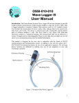
1
XBee-PRO® 900HP Development Kit
Getting Started Guide
90002172_B
5/8/2013
©2013 Digi International Inc.
All rights reserved.
Digi, Digi International, the Digi logo, the Digi web site, a Digi International Company, Etherios, the Etherios logo,
the Etherios website, Device Cloud by Etherios, XBee, and Digi XBee-PRO are trademarks or registered trademarks
of Digi International, Inc. in the United States and other countries worldwide. All other trademarks are the
property of their respective owners.
All other trademarks mentioned in this document are the property of their respective owners.
Information in this document is subject to change without notice and does not represent a commitment on the
part of Digi International.
Digi provides this document “as is,” without warranty of any kind, either expressed or implied, including, but not
limited to, the implied warranties of fitness or merchantability for a particular purpose. Digi may make
improvements and/or changes in this manual or in the product(s) and/or the program(s) described in this manual
at any time.
This document could include technical inaccuracies or typographical errors. Changes are periodically made to the
information herein; these changes may be incorporated in new editions of the publication.
© 2013 Digi International, Inc.
2
Table of Contents
Using this Guide............................................................................................................ 1
Conventions used in this Guide .............................................................................. 1
Contact Information................................................................................................. 1
Introduction .................................................................................................................... 2
Goals of the Kit ....................................................................................................... 2
Requirements of the Kit .......................................................................................... 2
Part 1: Set up your XBee-PRO 900HP Development Kit..................................... 3
Identify Kit Components.......................................................................................... 3
Assemble your Kit ................................................................................................... 4
Part 2: Download and Install X-CTU Software....................................................... 5
Installing USB Drivers ............................................................................................. 5
Installing X-CTU Software ...................................................................................... 5
Part 3: Test Communications Link and Establish a Mesh Network................. 6
Perform a Range Test ............................................................................................ 6
Part 4: Configure the Modules................................................................................. 12
Configure Remote Modules .................................................................................. 12
Change from Mesh to Point-to-Multipoint Mode................................................... 13
Change Firmware Versions .................................................................................. 14
Part 5: Managing the Network ................................................................................. 16
Digi Gateways ....................................................................................................... 16
To the Cloud! Make the most of your data. .......................................................... 17
To the Cloud! Take control of your device network. ............................................. 17
Appendix A: Troubleshooting .................................................................................18
Resetting the XBee-PRO 900HP Module ............................................................ 18
Why are the modules no longer communicating with one another? .................... 18
© 2013 Digi International, Inc.
3
Using this Guide
Conventions used in this Guide
This icon indicates a hint, or concept that is learned.
This icon indicates that a goal of the kit has been completed.
This icon indicates a warning of the potential for confusion or danger.
Contact Information
For more information about your Digi products, or for customer service and technical support, contact
Digi International.
To Contact Digi International
Use
Digi International
Mail
World Headquarters
11001 Bren Road East
Minnetonka, MN 55343
Phone
8:00 AM - 5:00 PM (U.S. Mountain Time)
1-866-765-9885 toll-free USA and Canada
1-801-765-9885 Worldwide
Online Support
http://www.digi.com/support/eservice/
login.jsp
Email
[email protected]
© 2013 Digi International, Inc.
1
Introduction
Thank you purchasing an XBee-PRO 900HP Development Kit. This kit is designed to make it easy to set up
an XBee mesh network, send data from one XBee to another, and adjust the XBee settings. Before you
start working with the kit, let's cover some basics.
Goals of the Kit
As you go through the steps in this kit, you will:
1. Set up you XBee-PRO 900HP Development Kit.
2. Download and install X-CTU configuration software.
3. Perform a range test.
4. Establish a network.
5. Configure the modules.
Requirements of the Kit
System Requirements
To install the software mentioned in this guide, you will need a PC running Microsoft Windows
2000, XP, Vista or Windows 7.
Additional Documentation
For more information about the software, API operations, AT command modes, or the form
factor please refer to the XBee-PRO 900HP Product Manual.
For more information on configuring and using the X-CTU utility, please refer to the X-CTU
Configuration & Test Utility Software User's Guide.
© 2013 Digi International, Inc.
2
Part 1: Set up your XBee-PRO 900HP
Development Kit
Identify Kit Components
Carefully unpack and verify the contents of your kit. Your kit should include the following:
Antenna U.FL (1)
XBee-PRO RPSMA Module (1)
XBee Interface Board (3)
© 2013 Digi International, Inc.
XBee-PRO U.FL Module (1)
Power Supply (2)
XBee-PRO Wire Module (1)
Power Supply Adapter (2)
(International Only)
USB Cable (2)
Antenna RPSMA (1)
3
XBee-PRO® 900HP Development Kit Getting Started Guide
Assemble your Kit
To assemble your kit, perform the following steps:
1. Install the modules on the XBee Interface Boards (XBIB) by lining the pins up with the headers and
pressing the module into place.
2. Attach the dipole antennas to the modules.
3. Connect the first XBIB to your computer using a USB cable. This first device will be designated as
your base module.
4. Connect the remaining modules and interface boards, and set them aside for now.
You are now ready to run the X-CTU software and to begin configuring your XBee Mesh network.
You have just completed Goal #1 - setting up your
XBee-PRO 900HP Development Kit.
© 2013 Digi International, Inc.
4
Part 2: Download and Install X-CTU Software
For proper kit configuration and operation X-CTU software (version 5.15 or later) must be downloaded
and installed. A copy of X-CTU software and USB drivers will need to be installed on each computer used
in conjunction with this guide.
Installing USB Drivers
The XBee USB interface board is a "plug-and-play" device that should be detected by the PC
automatically. If you are using Windows 7 or Vista, the USB drivers should automatically install and a
notification will appear in the lower right portion of your screen indicating success or failure.
If the USB drivers fail to install, please follow the USB driver installation instructions found here:
http://www.digi.com/support/kbase/kbaseresultdetl.jsp?id=3214.
If you are using Windows 2000 or XP, download and install the driver as per the following directions.
To install the USB driver:
1. Download the driver setup file at:
http://ftp1.digi.com/support/driver/FTDI_Windows_Driver_Setup.exe.
2. Double-click on the setup file. A window will pop up during installation and automatically close
when the process is complete.
Installing X-CTU Software
1. Download X-CTU at www.digi.com/xctu.
2. Browse to the folder to which you saved the above install file.
3. Double-click on the installer file and follow the X-CTU Setup Wizard.
4. When asked if you would like to check Digi's web site for firmware updates, click Yes.
5. After the firmware updates are complete, click Close. Updates may take a few minutes, please be
patient.
6. Start X-CTU by double-clicking on the X-CTU icon on your desktop, or by selecting Start > Programs
> Digi > X-CTU.
The X-CTU software is now ready to be used.
You have just completed Goal #2 - downloading and installing
the X-CTU configuration software.
© 2013 Digi International, Inc.
5
Part 3: Test Communications Link and
Establish a Mesh Network
Perform a Range Test
Before running a range test, you will need to establish a connection with the X-CTU software:
1. Double-click the X-CTU shortcut on your desktop.
2. Under the PC Settings tab, select the serial COM port associated with the development boards you
have just attached to your computer.
3. Verify that the baud rate and data settings match the internal settings of the devices:
• Baud Rate: 9600
• Flow Control: NONE
• Data Bits: 8
• Parity: NONE
• Stop Bits: 1
© 2013 Digi International, Inc.
6
XBee-PRO® 900HP Development Kit Getting Started Guide
4. Click the Test/Query button to verify communication with the module. A pop-up will be displayed
showing status and some basic information.
5. On the Modem Configuration tab, click Read.
6. Apply power to the second module using a power supply in a fixed location. This will be designated
as your remote module.
Note: You will need to have a jumper at P8 on the loopback header on the XBIB
for the remote module.
Ensure that the P8 jumper is not bridging the two pins together on the base
module. This could cause X-CTU to stall if the jumper is populated and requests
are sent to the module.
(bridged)
© 2013 Digi International, Inc.
(non-bridged)
7
XBee-PRO® 900HP Development Kit Getting Started Guide
7. Select the Range Test tab.
8. (Optional) Check the “RSSI” check box to enable Received Signal Strength Indicator.
9. Click Start to begin the range test.
© 2013 Digi International, Inc.
8
XBee-PRO® 900HP Development Kit Getting Started Guide
10. Monitor the link quality by reading the Percent section on the Range Test tab. This section
displays the running percentage of good packets sent to the receiving module and looped back to
the base.
© 2013 Digi International, Inc.
9
XBee-PRO® 900HP Development Kit Getting Started Guide
As your distance increases beyond the maximum range of the modules, you
will start seeing greater packet loss.
11. Click Stop to end the range test.
The Advanced tab allows you the ability to increase the data receive time out. which defaults at one
second.
© 2013 Digi International, Inc.
10
XBee-PRO® 900HP Development Kit Getting Started Guide
You have just completed Goal #3 - performing a range test.
Establish a Mesh Network
After you have performed the range test using the first devices, it is time to extend your network by
adding a third device and establishing a mesh network.
1. Restart the range test.
2. Move the remote device further away from the base device until the signal is lost.
3. Assemble another module and interface board.
Note: Note: Do not put a jumper on the J8 connector of this XBIB.
4. Connect with a power supply and place this device halfway between the base and remote radios.
The intermediate radio bridges the gap between the remote and the base and reestablishes
communication. The network “self-healed” by redirecting communications as soon as a pathway became
available. The radios are configured for broadcast mode, so they can route information and
communicate with one another automatically.
© 2013 Digi International, Inc.
11
Part 4: Configure the Modules
Configure Remote Modules
You can configure the XBee modules over-the-air using X-CTU. To use this feature, the base device must
be configured for API mode.
1. On your base radio, go to the Modem Configuration tab in X-CTU.
2. Click Read and the parameter types will appear in the window.
3. Set AP = 1 on your base radio by clicking on the AP command in the Serial Interfacing folder in the
Modem Configuration window. For more information about the different API settings, see the API
section in the user manual.
4. Click the Write button.
5. Next, click Remote Configuration in the top left-hand corner of the X-CTU window. The network
window will appear.
6. Click Open Com Port and Discover. A list of network nodes will appear on the screen.
© 2013 Digi International, Inc.
12
XBee-PRO® 900HP Development Kit Getting Started Guide
By selecting a particular node from the list, you can interact with it as if it were connected to the PC
directly. Now you can read, write, and restore parameters on the main X-CTU window, and those
changes will occur over the air on the remote module selected in the Network window. Close the
Network window when you have finished with remote configuration.
Change from Mesh to Point-to-Multipoint Mode
By default, your modules come configured to operate in mesh mode. If you need to work a point-tomultipoint topology, changing your settings is simple.
1. Click on the Transmit Options (TO) command in the Addressing folder in your addressing
parameters.
2. Change the setting from C0 to 40. TO is a bitmask that controls several options including
acknowledgements and network topology. The top two bits of the TO parameter control how your
network transmits data. Mesh mode with ACKS is CO and point-to-multipoint mode is 40. For
more information, see the AT command section in the product manual.
© 2013 Digi International, Inc.
13
XBee-PRO® 900HP Development Kit Getting Started Guide
Change Firmware Versions
These modules can be configured for an RF data rate of 200 Kbps or 10 Kbps with a simple firmware
change. Some customers prefer to send information at a lower data rate to improve their receiver
sensitivity which increases range.
1. Click on the Modem Configuration tab in X-CTU.
2. Select the modem type from the Modem drop-down box that corresponds with the RF data rate
desired, XBP9B-DM for the 200 Kbps version or XBP9B-DP for the 10 Kbps version.
Note: DigiMesh is not available at the 10K data rate.
© 2013 Digi International, Inc.
14
XBee-PRO® 900HP Development Kit Getting Started Guide
3. The function set will auto populate with the version associated with the selected modem type.
4. Select the firmware version desired from the Version drop-down box. The default selected is the
newest version of the firmware.
5. Check the Always Update Firmware box.
6. Click the Write button.
You have just completed Goal #4 - configuring the modules.
© 2013 Digi International, Inc.
15
Part 5: Managing the Network
Digi Gateways
Now that you have an RF network running, it is important to know how to manage that network. X-CTU
software and the various RF module features provide great tools for on-site XBee configuration, firmware
upgrades, and network diagnostics. However, in many cases it is necessary to be able to perform these
functions from a remote location via the Internet. Digi has solved this problem by creating RF-to-Internet
gateways to allow remote access, monitoring and control of your RF network over the Internet.
In the diagram above, a Digi ConnectPort X2 gateway is used to connect an RF network (plus other
peripherals) to the Internet via either the Ethernet port or a cellular WAN connection. Note that
gateways are programmable and can also be used to run local applications, which can monitor/control
the RF network, with or without Internet connectivity.
© 2013 Digi International, Inc.
16
XBee-PRO® 900HP Development Kit Getting Started Guide
See http://www.digi.com/products/wireless-routers-gateways/gateways/ for an overview of Digi's suite
of gateway products. A simple ConnectPort X2 ZigBee to Ethernet gateway costs around $100 and can
quickly internet-enable your ZigBee network.
To the Cloud! Make the most of your data.
So you've created an RF network and connected it to the internet with a Digi gateway. Now what? The
next step is to decide what you want to do with all of that valuable data. Ask yourself some fundamental
questions. Does an application need to be developed, or is there an existing application that will be
utilized? How should the data be presented? Who will be using this data? Is the audience internal,
external or both? Whatever the answers to these questions, Device Cloud by Etherios™ can help you
realize your vision and meet your needs for data capture.
Device Cloud is a public cloud platform-as-a-service that allows any application, anywhere, to connect
with anything, anywhere. Device Cloud takes care of the infrastructure, scalability and security, letting
you focus on what you do best - developing awesome products and applications. Get up and running with
Device Cloud for free and connect your device to explore what Device Cloud can do for you. Simply go to
www.etherios.com/devicecloud and click on Get Started Now to set up a free demo account.
To the Cloud! Take control of your device network.
Picture this. You have a network of thousands of devices to manage, many of them remote. You need to
update firmware, edit configurations, download software onto the various device types, dealing with IP
addresses, firewalls, security and server reliability. Sounds like a mammoth task. The Device Manager
application, hosted on Device Cloud, meets this challenge head on, allowing you to connect, control and
monitor the vast array of devices in your network. Perfect for large-scale deployments, you can group
devices and schedule operations, making device network management easy. Take a tour of Device
Manager at http://www.etherios.com/devicecloud/devicemanager and get started for free.
© 2013 Digi International, Inc.
17
Appendix A: Troubleshooting
Resetting the XBee-PRO 900HP Module
Each XBee USB Development Board has a reset button (located as shown below):
Pressing this button power cycles the module, but will not clear any changes written to the module. This
is useful if you are having issues accessing the COM port. This will also reset any parameters that were
changed but not written into memory.
Note: The remaining buttons are connected to various I/O lines and are not
used in this kit. See the product manual for more details relating to this
functionality.
Why are the modules no longer communicating with one another?
Network settings that can cause loss of communication include Baud Rate (BD), Parity (NB), and
Encryption Enable (EE) among others. Check to see if these parameters are set appropriately. If you are
unsure if your settings are affecting your communication, you might want to try setting your modules
back to their default settings. To do so, go to the Modem Configuration tab in X-CTU and click Restore.
© 2013 Digi International, Inc.
18