1
CWOPS Awards Manager (CAM) (Version 1.9.3, 14 August 2011) Automated CWops Awards Manager Software Specifically for Windows XP and Windows 7 PCs B&B Cyber Enterprises Kimberling City, MO 65672 Phone: 417-231-4542 Internet: http://bbcyber.com Copyright © B&B Cyber Enterprises, 2010-2011 COPYRIGHT NOTICE All computer programs and documentation developed in conjunction with the CWops Award Manager computer software are protected by federal copyright laws and, as such, may not be duplicated or used in any manner other than as described below. Copies of the distribution software disks may be made and distributed freely as long as the programs contained on the disks have not been modified in any manner. Registration numbers supplied by B&B Cyber Enterprises for specific callsigns may not be transferred to another user. Software programs that have been registered may not be sold, given, or otherwise transferred to another party. Multiple copies of CWops Award Manager may be used by the original registered user on as many computers as necessary to make the program available for personal use and needed backups. SOFTWARE LICENSE AGREEMENT B&B Cyber Enterprises provides this software to you, the end user, on the express condition that you agree to the terms provided in this software license. By transferring the programs on the supplied disks to your system or downloading a copy of the software from any electronic media such as the Internet, you agree to the terms set forth below. You May use the software on as many computers under your control as needed to make the program available to you at all times. You May make backup copies of the registered software for archival purposes only. You May make a copy of the unregistered and unmodified software and give that copy to another person for the purpose of demonstrating or evaluating the software. Your May Not give, sell, or in any manner transfer a copy the registration number to a third party. You May Not disassemble, reverse engineer, or in any manner duplicate either exactly or in a similar manner, the overall functionality of the software. REGISTRATION Other than the use of the unmodified program for evaluation, all users should register their copy of the program before use. Since the registration process includes input of the user's US Federal Communications Commission (FCC) or other country's officially issued callsign and a user‟s unique registration number, it is quite obvious that the registered program is for use by a single individual. Users that are not licensed amateur operators may still register the program as a short wave listener (SWL). In this case, the user's callsign may be any sequence of letters or numbers totaling usually, between 4 and 8 characters that have been determined by B&B Cyber Enterprises to be unique within the CWops Award Manager software registration process and not a valid amateur radio callsign in any known country. TRADEMARKS Windows95/98/ME/2000/XP/7/Vista are a trademark of Microsoft Corporation ARRL and DXCC are trademarks of the Amateur Radio Relay League CWops is a trademark of The CW Operators Club, Inc. WARRANTY This computer software, consisting of all supplied files pertaining to the CWops Award Manager program, hereafter referred to as the Software, is supplied "as is" with no other warranty implied other than that described here. This Software is warranted only to the extent of replacement of defective disks. Registered users may download replacement files directly from B&B Cyber Enterprises for as long after registration as the software is supported, including upgrades. This Software is intended for use as a database manager for contacts made between amateur radio operators. If software glitches or bugs, as generally defined by the software community, are identified, B&B Cyber Enterprises will review such and make a determination as to whether the glitch or bug has a major effect on the operation of the program. If deemed necessary by B&B Cyber Enterprises, the software will be updated and a revised copy will be made available via the Internet (http://bbcyber.com/cam). This Software is not intended to be used for any purpose other than for recreational purposes, which includes: use as a storage medium for the amateur radio hobby. In no case should this Software be used as a reference for any development, test, or reference, since this Software does not use validated algorithms for any of its processes. In most instances algorithms used have been optimized for speed or function, as required by the program. B&B Cyber Enterprises does not warrant that the software will operate on all computers. The best procedure is to try the program first by downloading the software and testing it on your machine prior to registering it. DISCLAIMER B&B Cyber Enterprises reserves the right to make periodic changes, enhancements, revisions, and alterations of any kind to the software and/or user's manual(s) without any prior notice to any person, institution, or organization. ii CONTENTS CWOPS Awards Manager (CAM) .........................................................................................................................i 1. SOFTWARE OVERVIEW ...................................................................................................................................1 2. SYSTEM REQUIREMENTS ................................................................................................................................ 2 2.1. Software. ............................................................................................................................................................ 2 2.2. Hardware. ..........................................................................................................................................................2 3. SOFTWARE INSTALLATION ............................................................................................................................ 3 3.1. Program. ............................................................................................................................................................ 3 3.2. Step-by-Step CAM Setup Procedure. ................................................................................................................4 3.2.1. ADIF File Import. ..........................................................................................................................................5 3.2.2. Single QSO Manual Entry. ............................................................................................................................ 8 3.3. Upgrading From an Earlier Version. .................................................................................................................9 3.4. Upgrading After Version 1.9.3. ....................................................................................................................... 10 3.5. Registration. ..................................................................................................................................................... 10 3.6. New “Add To Personal DB” Feature. .............................................................................................................. 11 4 AWARD STATUS SCREENS. ........................................................................................................................... 11 4.1 Startup Screen. ................................................................................................................................................ 11 4.2 ACA Award. ................................................................................................................................................... 11 4.3 CMA Award. .................................................................................................................................................. 13 4.4 WAS Award. .................................................................................................................................................. 13 4.5 WAE Award. .................................................................................................................................................. 15 4.6 DX Award....................................................................................................................................................... 15 5 MEMBER QUERY/STATUS SCREEN. ............................................................................................................ 16 5.1 Member Data. .................................................................................................................................................. 16 5.2 Monitor Band. .................................................................................................................................................. 17 5.3 Cluster Cmd and Send Buttons. ....................................................................................................................... 17 5.4 Remote Indicator ............................................................................................................................................. 17 5.5 Server ............................................................................................................................................................... 18 5.6 Telnet Related Buttons. ................................................................................................................................... 18 5.7 Hold Spots Button............................................................................................................................................ 18 5.8 Special Mouse Control Functions. ................................................................................................................... 18 6 TELNET/SKIMMER SETUP SCREEN. ............................................................................................................ 19 6.1 Host Callsigns. ................................................................................................................................................. 19 6.2 Select Telnet. ................................................................................................................................................... 19 6.3 Band Filter or Skimmer Scan/Filter. ................................................................................................................ 19 6.4 Spot Source. ..................................................................................................................................................... 20 6.5 Sounds. ............................................................................................................................................................ 20 6.6 Automatic Telnet Server Connections and Re-Connects ................................................................................. 20 6.7 Display and Color Rules. ................................................................................................................................. 21 6.7.1 CWops Only ................................................................................................................................................ 21 6.7.2 ACA Needed Only ....................................................................................................................................... 21 6.7.3 CMA Needed Only ...................................................................................................................................... 21 6.7.4 Show Worked CWops ................................................................................................................................. 21 6.7.5 USA Sources Only ....................................................................................................................................... 21 6.7.6 Hide ANN Spots .......................................................................................................................................... 21 6.7.7 Hide WWV Spots ........................................................................................................................................ 22 6.7.8 Color LoTW QSOs ...................................................................................................................................... 22 6.7.9 Pass Prefix ................................................................................................................................................... 22 6.8 Examples of Setups For Different Types of Operations. ................................................................................. 22 6.8.1 CAM as a General Telnet Client .................................................................................................................. 22 6.8.2 Using CAM to Identify CWops Members ................................................................................................... 22 6.8.3 Using CAM While Operating a CWT ......................................................................................................... 23 6.8.4 CAM Combining Spots for a General Contest Operation ........................................................................... 23 7 SERVER SCREEN. ............................................................................................................................................. 23 iii 7.5 Server IP Address and Port Number. ............................................................................................................... 23 7.6 Use Remote Commands. ................................................................................................................................. 23 7.7 Server Filters. ................................................................................................................................................... 24 8 ALERTS/BAN SCREEN. ................................................................................................................................... 24 8.1 Alert Functions. ............................................................................................................................................... 24 8.2 Spot Options. ................................................................................................................................................... 25 8.3 TXT MSG Setup. ............................................................................................................................................. 25 8.4 BANNED SPOT SOURCES LIST. ................................................................................................................. 26 8.5 PASS ONLY - STATES LIST. ....................................................................................................................... 26 9 MEMBERS LISTING, WORKED, and LAST HEARD SCREEN. ................................................................... 26 9.1 Worked designator. .......................................................................................................................................... 27 9.2 Last Heard Function. ....................................................................................................................................... 27 9.3 Total Members Spotted.................................................................................................................................... 27 10 CAM OPERATING TIPS. .............................................................................................................................. 27 10.1 CWops Member Callsign Display. .................................................................................................................. 27 10.2 Database Errors................................................................................................................................................ 30 10.3 Viewing the Database ...................................................................................................................................... 30 10.4 Finding User Call from CWops Number ......................................................................................................... 30 10.5 Turn Display Off/On........................................................................................................................................ 31 10.6 Holding and Resuming Spot Processing .......................................................................................................... 31 11 CAM File formats. ........................................................................................................................................... 31 12 USE OF AUTOHOTKEY TO CHANGE THE RADIO FREQUENCY. ....................................................... 34 12.1 AutoHotKey Script .......................................................................................................................................... 34 12.2 Find Mouse Coordinates for AutoHotKey ....................................................................................................... 35 iv 1. SOFTWARE OVERVIEW The primary purpose and use of the program is in conjunction of managing and storing information pertinent to making amateur radio contacts (QSOs) and tracking the an individual amateur‟s progress toward satisfying the requirements for performance levels as those QSOs relate to specific awards managed by the CW Operators Club. Among those awards are: CWops ACA -- Annual Competition Award. CWops CMA – Cumulative Membership Award. CWops WAS Award. Worked All States. CWops Worked All Europe Award. CWops DX Award. See the website: http://www.cwops.org/awards.html for specific data for each award. The CWops Award Manager (CAM) software supports all five of the above awards programs, including their derivatives as they pertain to specific amateur radio frequency bands. Features included within the CAM software include: Award specific QSO information storage. Maintaining status on each award for the single file of QSOs with other CWops members. Generating lists of QSOs pertinent to each separate award level. Most awards are tracked by frequency bands with the single exception of the ACA award which consists of making a single contact with as many members as possible during a year long period. At the beginning of each calendar year the award resets and starts over again with zero QSOs. The software is access through a set of tab pages, each targeting a different award of operating function. The software also serves as a lookup during non radio operating times and during radio operations. The callsign lookup function is implemented on the Member Query/Status tab. During operations, the software can be used to monitor local or internet accessible servers that are used to announce the callsigns, frequency and date-time of each amateur station that has been spotted. The spotting originates from either individual operators or from software defined radios (SDRs) that can monitor wide bands of frequencies simultaneously, reporting callsigns associated with individual amateur radio transmissions as they pertain to mainly members of the CWops Club members. Transmissions by other than members of the club can also be monitored or filtered out of the data stream using the CAM software. Connects to the internet or internet/local network telnet servers. Can control the frequency bands of local or remote SDRs and their servers. Can sequentially scan defined radio frequency bands for user input lengths of time before changing to the next frequency band. Generates “stations needed” and “stations worked” listings for each award. Generates audible and visual alarms when a callsign is recognized that is associated with a “needed” QSO. Specific callsigns of importance to the user can be entered and monitored over and above the other monitoring functions supported within the CAM software. Uses the Windows clipboard to allow for transferring the frequency information associated with a specific callsign of members and non-members. Spotted station information can be transferred to Logger software such as N1MM or DX4Windows using script files for functions processed by “AutoHotKey”, which is a free software utility program. CAM is a dot net (.NET) Visual C Sharp (C#) program that uses the .Net version 3.5 Framework. 1 CAM software does not require an installation file, the software is supplied as a zip file that can build the appropriate directories and transfer the required files to the user‟s computer. CAM software includes information tabs for specific functions, but this manual actually provides the detailed descriptions of the operations and syntax used with the program. 2. SYSTEM REQUIREMENTS 2.1. Software. The use of CAM software requires that the host PC system use at least the Windows XP operating system. In addition to XP, Windows 7 has been tested and is the recommended operating system. Windows Vista should probably work fine, but has not been tested with CAM. The CAM software is a 32-bit application and will not run under DOS, Windows95, or Windows 3.1. CAM is also a dot NET application, written in “C” Sharp (C#), a dot NET language. CAM requires that the dot NET software Framework version 3.5 or later be installed on the host system. CAM was developed in such a manner as to not require an installation program, and it will not add to or modify the Windows registry. CAM along with the required folders can be copied to any r/w disk or folder and run from that location. CAM is supplied as a zip file and should be unzipped to the root folder of a disk drive. Other software: CAM was developed for use in conjunction with the free, N1MM Logger and was tested with both ADIF files and Cabrillo files, both types exported from N1MM. In addition, ADIF files downloaded from ARRL‟s Logbook of The World (LoTW) have been tested and work properly. ADIF files from the DX4WIN program have also been shown to work with CAM. See the website for the N1MM Logger at http://www.N1MM.com . In order to transfer frequency information from CAM to N1MM, the simplest method is to use the AutoHotKey utility and setup a script to transfer the frequency from the Windows clipboard to the callsign input block of the N1MM logger. A working script is included in the downloaded zip file. The link to download the free AutoHotKey utility is: http://www.autohotkey.com/download/ . Download the Source Code, which has the full AutoHotKey utility and will extract to the proper directories. CAM works well with the CW Skimmer software, available from http://www.dxatlas.com . CW Skimmer is not a free program, but can be used for 30 days before registration is required. 2.2. Hardware. The CAM software requires a PC system consisting of an Intel or similar single processor running at a minimum clock speed of 1.8 GHZ. Dual or Quad processor will provided faster operation. In addition, the system must have: at least 1GB of RAM at least 512 megabytes of free hard disk space a VGA or better display adapter with color System Beep function is used, but will use a sound card for alarms if one is available. To use CAM with a SDR receiver such as the RF Space, model SDR IQ, CWSkimmer software is required. If no SDR or CWSkimmer is used, there are hundreds of TELNET spotting web servers available than can be used to provide DX and local spots for the monitoring functions within the CAM software. Both notebook and desk type systems have been used for testing. Based on the actual setup of the hardware and operating system, slower systems could cause the sound output to skip slightly and slower clock speeds also limit the use of SDRs and increase the time needed to produce listings and current scoring results for especially the CMA award. The CMA calculations take longer because they have to evaluate the log entries vs. the eleven bands supported by CAM. Additional RAM or a faster processor can minimize the fore-mentioned negative characteristics. B&B Cyber Software 2 does not warranty or guarantee that the software will work on all types of computers or specific operating system setups. The best method is to test the software first before registering it. 3. SOFTWARE INSTALLATION 3.1. Program. Prior to copying the CAM files to your computer, verify that the dot NET Framework, version 3.5 or later has been installed. If not, install the Framework available from Microsoft for free at: http://www.microsoft.com/downloads/details.aspx?FamilyId=333325fd-ae52-4e35-b531508d977d32a6&displaylang=en . Make sure you select the full redistributable package. Once the file named dotnetfx35.exe has been downloaded, execute it and install the dot NET Framework. There are updates to the version 3.5 Framework (SP1), but CAM will work properly with or without the updates. Updates can be found on the same Microsoft website referenced by the link above. CAM is distributed both electronically (via the Internet) and by CD, direct from B&B Cyber Software. In either case, the distributed software consists of an installation file named similar to this: “CAM_Full_Install_v1.9.3.exe”, which is a self-extracting zipfile. The setup program may be run from any location on the computer, just double click on the file and then extract all the files to the location that is desired. The suggested and default location is “C:\”. Once the files are extracted, you will have a folder on the C: drive titled “CWops Award Manager.” Within that folder, you should see a file named, “CWops Award Manager.exe,” which is the main program. Other files and sub-folders within that folder are required and should include the following files. cwops.ico install.txt CAM Upgrade Notice.exe a folder named – Award Submittals a folder named – CAMBackupFiles a folder named – DataFiles a folder named – Documentation a folder named – LogFiles a folder named – TempData a folder named – Verification Within the DataFiles folder, there should be these files: arrl_cty.txt CellCarriers.txt Clusters.txt FOCDataList.txt – has a maximum of 500 members LastHeard.dat lotw1.txt MemberDataAddOn.csv – currently not used, but left for compatibility issues MemberDataList.csv – CWops generated member data file wae.dat NOTE: The up-to-date member data is always included in the setup file available on the webpage: http://bbcyber.com/cam . The download directory is username and password protected to protect sensitive personal data that it is in the CWops membership data file. The file obtained from the CWops website is only updated monthly, but the add-on file usually updated within 24 hours of the Member Roster being updated on the CWops website. Within the Documentation folder, there should be two files: CAM_Manual-1-9-3.pdf Install.txt 3 The LogFiles folder is a convenient location to store the ADIF or CABRILLO formatted log files used to populate the CAM database. The remaining files should be empty except for a notice describing what should be saved there. 3.2. Step-by-Step CAM Setup Procedure. When new versions of CAM are announced it is always recommended that you update your installation main for bug fixes, but additional features are usually included. If you are upgrading from an earlier version, follow the procedure in section 3.3, the same as a full installation. STEP 1: From the CAM webpage, http://www.bbcyber.com/cam , click “Free Registration” and enter your callsign in the text area of message outline and send the email to [email protected] . Your registration number will be sent to you as soon as possible, usually within the hour for work days. STEP 2: Make sure the CAM files have been copied to the computer and that the dot NET Framework, version 3.5 or later has been installed. STEP 3: Make a shortcut for “CWops Award Manager.exe” and place it on the desktop. Double click the shortcut, to start the CAM program. The screen shown in Figure 3-1 should appear. Enter your callsign in the “Callsign” textbox. Press tab once to move to the “Auto Fill” button. Click “Auto Fill”, all of user data as defined in the CWops member data file should appear. Press tab once to move to the “Logging SW” textbox, click the small down arrow in the textbox (a list of supported logger ADIF files should appear), then select your logger type from the drop-down menu list. e. Press tab once to move to the “Year For ACA” textbox, and enter the year that you want to use when viewing your status for your ACA award. This is the default year, you will still be able to move between other years when viewing other year ACA status. f. Press tab once to move to the “Registration Key” textbox and enter the registration key obtained by email in step 1 above. If you want to run the program without registering, you may do so and register later (in this case, just leave the “0” in the “Registration Key” textbox. g. The filled-in “User” tab should look similar to that shown in Figure 3-2 on the next page. h. Click the “Continue Setup” button to continue. a. b. c. d. Figure 3-1. Initial Setup Screen. 4 Figure 3-2. Setup Screen With User Data. After clicking the “Continue Setup” button, the ACA Award tab will appear as shown below in Figure 3-3. Since at this point, you do not have any QSOs entered into CAM the Award will show “0” in the “Worked” textbox. Figure 3-3. Blank ACA Award Status Tab. There are two methods for adding QSO information to the database. You can enter the data using an ADIF formatted file, containing the QSO information that you have exported from your logger software, or a similar file you have downloaded from the Log Book of The World (LoTW). Method 1 – ADIF file import. Method 2 – Single QSO manual entry. These two methods are explained in the next section. 3.2.1. ADIF File Import. Use the “ADD QSOs From File” tab, which can be found under the top level tab labeled “QSO Database,” see Figure 3-4 and follow the steps, as outlined below. 5 Figure 3-4. ADIF File Import Screen. Step 1: Verify that the Database Filename block displays the user‟s callsign, with the data extension. If it does not have the correct callsign, it usually means that the User Data was not filled in correctly, in that case, return to the “User Data” tab and verify the information entered. It should show the user callsign in the callsign block. If not, Delete the file named “cam.ini” in the main folder and start over. Step 2: Click the Browse button and navigate to the ADIF file or Cabrillo file, containing the QSO information that describes QSOs with CWops members, on or after 3 Jan 2010. Verify that the file is “.adi” or a Cabrillo file, which usually has a “.log” filename extension. There are contest specific formats for Cabrillo formatted files. CAM must be told exactly where it can find the worked station‟s callsign is in the QSO line before a specific Cabrillo file will work properly. The ones that were tested included the Cabrillo file exported from the N1MM Logger software, when the monthly mini CWT test was selected as the contest name and a few other files to make sure that the correct position was entered for the “Call Loc” value, found under the Cabrillo selection option. In either case, make sure the proper type of file is selected. NOTE: To find the Callsign Location start number, open the Cabrillo file with the windows Notepad or WordPad program. Locate a line starting with “QSO:”. Beginning with the “Q” character as number one, count to the right until you get to the first character of the callsign of the worked station. That is the number you would then place into the “Call Loc” value. The number is 63 for N1MM generated Cabrillo files for the CWops CWT mini-contests. Step 3: Select the file and click “Open.” Click the “Add QSOs From Source File” button. The process should quickly complete and display the message: “” If there are QSOs in the file with CWops members that are using a portable designator (examples, K9FN/M or SV9/OH1VR) then CAM may display additional selections to allow you to define what location the QSO actually pertains to. See Figure 3-5. NOTE: Alaska and Hawaii are treated as DX, but also as US states for WAS Awards. In the cases of Alaska and Hawaii, use either KL or KH6 for the country and AK or HI for the state. Use the drop-down list of countries to select the country for the QSO. Also fill in the State/Province, if the operation was from either the Continental USA or Canada. The state block should be automatically filled in with a double dash if a country other than the USA or Canada was selected. You also may click on the “QRZ.COM” button to aid in determining the country/state information. You may also skip the QSO if you need to. When the Country and State/Province is filled up properly, click the “Add” button to continue. Repeat the processes until the “All QSOs in file added” message appears. The message will only show for a few seconds and disappear. Another file may be selected to add additional QSOs or you may select another tab. 6 Mobile stations are a particular problem, in that you must have a way of finding out where the station actually was when you worked them. For mobiles, it is usually a good idea to enter the state in your logger information block when you actually work them. You can also find references by doing a Google search on the mobile callsign, which sometimes produces the history of a trip or spots from DXWATCH that include the state or county where he was at a given time. Also, if you think it may have been a state that you need for the WAS award, you can always send a quick email to the person you worked and confirm the station location on that date. Figure 3-5. Annotate QSO Location for Portables After all of the QSOs have been processed, statistics are available (see figure 3-6), showing the number of member QSOs found in the file, the number of those member QSOs that were added to the “yourcallsign.data” that resides in the “DataFiles” folder. The number of non-CWops members QSOs found and the total QSOs found in the file are also displayed. Note that the number of members QSOs and the number of non-members QSOs, should add up to the Total QSOs number. If the two numbers do not total up to the Total, that means that there were errors in the ADI file itself and one or more QSO entries were not processed. Figure 3-6. After Dupes removed and verify/Repair has been run. 7 Notice that there are buttons labeled “Remove Dupes Database” and “Verify/Repair Database”. After adding QSOs to your database, you should click the “Remove Dupes Database” button once to remove duplicate QSOs from the database. CAM disregards all QSOs made with non-members. CAM only needs a single QSO for each member/year for the ACA award; for each member/band for the CMA award; for each band/state for the WAS award; for each band/WAE-Country for the WAE award; and for each band/DX Country for the DX award. Clicking the “Verify/Repair Database” button will run a sanity check on all QSOs. If there are any common errors; such as wrong country abbreviation or invalid state, the program will attempt to correct the entry for you. Clicking the button more than once will usually show that there “0” errors fixed the second time. If you still cannot find the a given QSO in the particular award, check that the credit is not already been taken by another QSO for a state or a country. If all else fails, check the “yourcallsign.data” file in the DataFiles subdirectory to try an identify what the problem is. You can modify the data file with a pure text editor, but be careful and make a backup first, because an untold number of errors could result from a corrupt data file. 3.2.2. Single QSO Manual Entry. You can use two methods to enter a single QSO into the database. The easiest method is; while viewing the “Member Query/Status” tab, right click on the line containing the spot information of the station that you just worked. The screen similar to the one shown in Figure 3-7, below, should appear. The information will be automatically entered in the appropriate text blocks, including the current date and time. If you need to adjust any of the data, do so. When satisfied, click the “Add QSO To Database File” button. The data will be added into the callsign.data file in the DataFiles folder. A notice will briefly appear to notify you whether the data was accepted or not. If you click the “Add…” button again, the program will not accept another entry because that member will now have a valid QSO in the record for that band. The second method is similar to the one previously described, however you must navigate to the “Add Single QSO” tab and then enter the data manually. Use the “ADD Single QSO” tab, which can be found under the top level tab labeled “QSO DB”. Enter the callsign first and press the <Enter> key. The CWops member data will automatically populate the text fields, but you may have to modify date/time/band, or even country/state. Similar to the first method, when you are satisfied with the data to be saved, click the “Add QSO To Database File” button”. Figure 3-7. Add Single QSO Screen STEPS REQUIRED TO ENTER A QSO MANUALLY Step 1: Verify that the “Database Filename” block displays the user‟s callsign, with the data extension. If it does not have the correct callsign, it usually means that the User Data was not filled in 8 correctly, in that case, return to the “User Data” tab and verify the information entered, where it should show the user correct callsign in the callsign block. If it is an incorrect callsign, correct it. Step2: Enter the QSO callsign in the “Call” block. If it is a portable station that was worked, do not enter the portable data until after the other data has been entered. Press <Enter> to populate the station‟s member number, name, and date information. Change the date if needed. The home country and state/province is automatically entered. This will have to be manually changed if the station was out of the home QTH area. Note: For members using another station‟s callsign, such as happens during multi-op contest operations, you will have to fill in all data by hand. Put the actual member‟s callsign in the callsign block and the QSO information in the appropriate blocks. Step 3: Enter the time of the QSO in GMT(Zulu), in “HHMM” format. Step 4: Select the band the station was worked on by clicking the appropriate option, found to the right of the Band block. Select the Country and State/Province (if applicable) from the appropriate drop-down list. Step 5: If the callsign of the station worked was a portable, go back to the callsign and add the portable information. Step 6: Click the “Add QSO To Database File” button. If no errors are detected in the format, a notice will be displayed for a few seconds verifying that the operation was completed. If you can‟t remember whether you pressed that “Add QSO…..” button, press it again and if you did, the program will tell you that you don‟t need the QSO. 3.3. Upgrading From an Earlier Version. Versions earlier than 1.9.2 should be upgraded . Use the Install/Upgrade Self-Extracting EXE file, available the webpage http://www.bbcyber.com/cam . Updates on the webpage contain a set of complete data for all members, including the start date and a termination date if a previous member has left the club, changed callsigns, etc. If you have installed an earlier version in a directory other than the one named “C:\CWops Award Manager”, you should use the Install program, which will build a new directory called “C:\CWops Award Manager”. After the install program is run, locate the “cam.ini” file in the old directory and move or copy that file to the “C:\CWops Award Manager” directory and then find you database file, named “yourcallsign.data” in the old “\DataFiles” folder and move or copy it to the new “C:\CWops Award Manager\DataFiles” folder. You should be able to then start CAM and your user data and QSOs should immediately be recognized by the program and displayed in the ACA tab listing. Upgrade steps below: STEP1: Download the Install/Upgrade self-extracting EXE file from the CAM webpage. STEP2: Run the program as administrator from any location on the computer. STEP3: The EXE file will replace or make all necessary files and folders that CAM requires. Note: The cam.ini file and the “Datafiles\yourcallsign.data” file will not be altered. STEP4: Start the program as required. If the program starts in the new user mode with no callsign entered, you do not have a valid “cam.ini” file and you will have to exit and copy the “cam.ini” file to the “C:\CWops Award Manager” directory or fill in the data as a new user. STEP5: You should see the status of the ACA award on the appropriate tab. If you see a value of “0” in the “Worked” textbox, you do not have a valid yourcallsign.data file. Either copy it to the “C:\CWops 9 Award Manager\DataFiles” folder or enter your QSO data using either the ADIF/Cabrillo or Single QSO entry methods explained earlier. 3.4. Upgrading After Version 1.9.3. With version 1.9.3 and later, the member database and the logbook of the world database can both be upgraded from directly within the program (see “System/Database Updates” tab)). This upgrade is only available for the databases. If another version of the program itself is available, the safest thing is to back up your current directory first, then download the file “CAM_Full_Install_v1.9.3.exe”, which is a self-extracting zip file. Run that file from anywhere on your computer and it will replace files that have been changed for the latest version. In some cases, a new subdirectory may be created as was recently done to provide a place to hold the last database update, prior to it being copied to the DataFiles folder. There is also an automatic check capability that will run each time the CAM program is started and retrieve the latest member database update and/or the latest list of „Logbook of the World” users. If the “Download on Startup” checkbox(s) is checked, updates are automatic and a program re-start will not be required. If you you use the “Update Latest ….” button(s) a message will appear to remind you that to use the new database(s), you must stop and re-run the CAM program. Figure 3.8. Manual and Automatic Database Updates. 3.5. Registration. The use of the CAM Software is totally free. However registration is required to access all of the program‟s features. The only information needed to register the program is your callsign and an email address to send the registration number back to you. We will only use the email address to send you a registration number and to inform you of updates to program critical files like the memberdata-daymonthyear.dat file, which contains the latest CWops membership roster information. CAM program updates, that add or change features or fix software bugs, will be announced both on the website and through email notices. When you register, you can stop all update information by typing “DO NOT EMAIL UPDATE NOTICES” within the comments section of the email from. If you turn off the updates feature, you will only receive a single email with the registration number. To register the program go to the internet webpage http://bbcyber.com/cam, navigate to the bottom of the page and click on the “Free Registration” link, which will automatically bring up an email form with the correct registration address. Enter you callsign and send the email. Your registration number will be sent by return email as soon as possible. You can continue to set up the program without the registration number and enter that number when you receive it. 10 The CWSkimmer scan function and the Alerts capability are not functional until the program has been registered, however all other features are fully implemented. There is no charge for the registration and no other information needed other than providing your callsign and email address. If you like the program and would like to donate a few dollars, use the “Donate” button on the CAM webpage at: www.bbcyber.com/CAM. Once you have received your registration number, just click the “User Data” tab and enter the number into the text block provided. The registration state, shown at the bottom left of the screen, and access to the extra features will not be changed until after you exit the program and re-start the program. 3.6. New “Add To Personal DB” Feature. The user may now enter non-member callsigns that have been used by members during, for example: dx-peditions, contests, or simple operating. The new feature allows the user to enter the new callsign and attach his membership numbers to QSOs that occur between two dates. The feature is assessable from the “QSO DB” TAB. Entries made with this feature will be stored in a file named as: “yourcallsign-AddOn.csv”. The instructions for use of this feature are shown on the “Add To Personal DB” Tab. 4 4.1 AWARD STATUS SCREENS. Startup Screen. New in version 1.9.x is a general summary screen that appears directly at program startup, except for the first time that CAM is run and the user information has not yet been entered. After initial setup, the CAM software will always start up showing the “Awards Summary” tab, see Figure 4-1 below. Figure 4-1. Awards Summary Screen. 4.2 ACA Award. After initial setup, the CAM software will always start up showing the “Awards” tab and the “ACA” award progress, see Figure 4-2 on the following page. The ACA Award tab provides the total number of CWops members worked for the year entered on in the “Year” text box, currently only years 2010 and 2011 are valid. The default year entered is the year as defined on the “User” tab and CAM automatically uses that stored date each time it is run. The Award Level labels change to Green backgrounds once the award level has been met for the year selected. The “Score Log DB” button will re-calculate the award progress if clicked. The only time you should have to click the button is if you changed the year or possibly if you added more QSO information by either the file or the single 11 QSO method. When changing from one award to another, the calculation is automatic. On the right side of the screen is a list of years and includes the total history to date for the current year and past year(s). The listing of QSO information shows the QSOs that are used for the award, the latest QSO with that member is shown. The list of ACA applicable QSOs can be saved in the “AwardSubmittals” folder by clicking the “Save List” button – the order of the saved list will be the same order as that viewed when the “Save List” button is clicked. You can use these type listings to verify QSO particulars against the database contents if you have both in chronological order. Figure 4-2. ACA Award. The ACA year award may be changed by clicking the “U” or “D” for up or down respectively. The program will not allow a year not yet reached or a year before 2010. Click the listing labels to sort the data based on the column. Figure 4-3 is the same as Figure 4-2, except; instead of being sorted alphabetically by the callsign, the data is sorted numerically by CWops number. Figure 4-3. ACA Award Listing Sorted on CWops Number. 12 4.3 CMA Award. Unlike the, yearly restarted, ACA Award, the CMA Award is a continuously running award. The object is to work all the members of the CWops Club on each amateur band. Progressive levels can be obtained by working 250, 500, 750, 1000, 1250, and 1500 QSOs, the only restriction is that a member can only be worked once per band for credit. The score is then the sum of unique member QSOs on each band. In addition to the all-band award, there are separate endorsements for the individual amateur bands. The CAM software initially supports eleven bands, 160 meters through 2 meters. It is envisioned that the bands supported could be expanded to include higher VHF and UHF bands, if there were to be enough participants to drive a program modification. The CMA tab has features that the ACA tab does not have or need as depicted in Figure 4-3, below. Figure 4-4. CMA Award Progress Screen. First, the band-by-band totals are displayed in their own totals blocks. Secondly, the display of QSOs by band is supported, just select the band of interest from the “Display QSOs” drop-down menu, on the left and when the list is re-scored and displayed, it will only contain the callsigns and member information pertinent to the selected band. Note: The green backgrounds for the 80M, 40M, and 20M bands indicate that the requirements for the CMA-250 awards values have been met for those bands using the single band. In the same manner as the display for the ACA Award, the QSO listings may be sorted in various ways to favor either callsigns, dates, times, CWops member numbers, bands, countries, or states. By clicking on the desired title bar a second time, the sorting will be done in reverse order. 4.4 WAS Award. Similar to the CMA award, the WAS award again supports the commonly used bands, 160M through 2M. The band titles change color from: red, indicating none worked on that band; yellow, working toward the award; and green, reached the “worked all states” goal on that band. See Figure 4-5. For the WAS award, CAM also incorporates a few additional features that the previously described awards do not use. A worked list and a want list are both available to the user by band. Access the worked list by clicking on the “WAS Status” button on the right. Click the button again to switch to the want list. Click the button again to return to the Display QSOs band selection menu. Figure 4-5 shows that all states needed for the primary all-band WAS Award have been worked. 13 The WAS Screen also supports a list of the worked stations. Access this by first selecting the band (160M) from the drop-down menu, shown on the left side of the screen in Figure 4-6. Then click the “WAS Status” button on the right side of the screen, also shown in Figure 4-6. Figure 4-7 shows the states worked on 30M and the list of those stations. Figure 4-5. WAS All-Band Award Sorted By State. Figure 4-6. WAS 160M Award Screen, Showing States, still Needed. 14 Figure 4-7. WAS 30M Band Award, Showing States Worked With Callsigns. 4.5 WAE Award. The WAE Award screen is shown in Figure 4-8 and is very similar in display and properties as the WAS awards tab, including the capability to display needed and worked listings by band. Figure 4-8. WAE Award Screen. 4.6 DX Award. The DX Award is another All-Band and Single-Band endorsable award. At this stage, the needed and worked listings are not too useful, since the DX worked list can be obtained by sorting the list of QSOs by country. The display and sorting capabilities are available from this screen as is band by band parsing of the main QSO listing. 15 Figure 4-9. DX Award Screen. 5 MEMBER QUERY/STATUS SCREEN. Figure 5-1 below, shows the primary CAM monitoring screen, where spots are displayed after filtering. Spots, shown in color, are CWops members. Those displayed with a Black font are nonmembers. An exception is that non-members that are LoTW members are shown in BLUE (default). The data in the upper right corner of the tab display indicates that the CWops database was updated through the data shown, 20110810, which corresponds to the last updated notation from the roster page at the cwops.org website, and the LoTW listing being used has 44,369 callsigns in the file. Figure 5-1. Main Operating and Monitored Screen. 5.1 Member Data. The line of boxes near the top of the tab page are data elements pertinent to the last CWops member spotted (that was needed or the last member left-clicked on in the listing), in the example case, the last member left-clicked was W5SG. Call, Name, CWops #, State/Province, and Country are taken from the member data file. Just below the member data, is a listing of bands available to work. Since four bands are green, that indicates that W5SW has been worked on 80M, 40M, 20M, and 15M, the other bands are “Red” indicating that the station hasn‟t been worked on those bands yet. If all labels 16 are RED, that means that the station has not been worked on any band and is therefore needed for both the ACA and the CMA awards and possibly others awards. The “QRZ.COM” tagged button under the “Call:” textbox, when clicked will display the QRZ.COM website‟s data concerning the callsign that is currently shown in the textbox, W5SG in this example. At the end of the line, the “LoTW” shown in “Green” indicates that W5SG is a member of LoTW. The “Green” label, “FOC” indicates that W5SG is also a member of the “First Class Operator‟s Club”. This feature was added because many of the CWops members are also FOC members. Another feature of the member data is that it is also available for member look-ups locally. Press the tab control until the cursor is in the callsign textbox, or click on the textbox with the left mouse button. Type a space to erase the current contents of the textbox. Type in any callsign, instantly, if the holder of the callsign is a CWops member, the data relevant to that member will be shown in the color Green. Clicking on any line in the list will produce similar results. For example, if the spot at the bottom of the list is clicked, the callsign DJ9DZ will be transferred to the callsign textbox, the callsign will be Black and the rest of the data textboxes will remain blank because, at the time of the writing of this document, DJ9DZ was not yet a member of CWops. If desired, the QRZ.COM button can still be used on the call to obtain similar information. There is a GREEN “LOTW” tag at the end of the line for DJ9DZ, indicating that that station uses the Logbook of the World for electronic QSLs. A special message is shown, if a past member of CWops is spotted. This message identifies the spot as one from a “Past Member” and that the Callsign is currently INACTIVE as it applies to CWops awards. 5.2 Monitor Band. The line of blocks near the bottom of the tab page and labeled with the amateur bands are used two different ways. If the connection is to a CWSkimmer and that skimmer is setup to allow remote commands, clicking on one of the band labels will change the skimmer monitored band to the band clicked. If the connection is to a TELNET website, clicking the same label will send a sh/dx <band> to the connected spotting network. 5.3 Cluster Cmd and Send Buttons. The user may send messages to connected telnet servers by typing a valid telnet server command in the text area. Commands like “Help”, sh/dx, sh/dx PJ, etc. can be entered in the text area. To send that command, use the send button associated with the currently connected telnet site that you want the command sent to. 5.4 Remote Indicator The green “Remote” indicator is shown only it the “Use Remote Cmds” checkbox is checked. This checkbox is located on the “Server” tab and is used to allow the CAM instance to act as a mirror of another instance of CAM running on another computer. This feature allow spots that show up on, for example, you computer that you use at your radio position to be sent to this second instance of CAM that may be running in your office or another room of the house on a computer that is connected to your local area network or even located in any location connected to the internet. When used in this manner, clicking a spot on the remote computer will automatically send a command to the other CAM process and cause it to change the frequency of the radio (if setup to do that function). Example: You are working at your desk and you have a remote CAM instance running on your desktop. A spot comes up that you are looking for. You click on that spot from your desktop and the frequency of the radio is changed and by what you hear, you may make the decision to go to the radio and try to work the station. If you can‟t hear the station, then you would probably elect to continue working at your desk. This feature was added to allow the radio to be quickly tuned to the frequency of the spot and save you steps and time when you can‟t hear the station. 17 5.5 Server If the “SERVER” checkbox at the lower left of the tab shown in Figure 6-1 is checked, then the server should be active and the background will be green and show both the local IP address and port number assigned to the CAM‟s embedded server. If unchecked, the background will be red. If no port is indicated, then a port has not been entered in the appropriate textbox on the “Server” tab. 5.6 Telnet Related Buttons. Buttons near the bottom right are used to connect to, clear the list of spots, and exit(disconnect) the selected telnet or skimmer or one of the other five telnet sites listed on the TELNET/Skimmer tab. A Green “RBN 7000” notice shows the status of the telnet connection and the short name of the telnet site. If the Connect-1 button is shown in GREEN, the program has determined that the link is working, but if it is shown RED, the telnet site is not sending update information to CAM and the user should click the “Connect-1” button again, which will disconnect and attempt a reconnect to the telnet site. Cluster commands may be sent by typing the command into the “Cluster Cmd:” text area, and sent by clicking the “SEND” button. This capability can be used to send spots also, if the server allows DX to be spotted. An additional cluster command, “sh/dx” can be sent simply by clicking the “sh/dx” button. To clear the list of stations, click the “Clear” button at the top of the list window. Additionally, by default, when a line in the spot listings is clicked, the frequency of the spot is transferred to the Windows clipboard. Use of that information is described in section 11 of this manual. 5.7 Hold Spots Button. The button named “Hold Spots” near the upper right corner of the spot list is used to temporarily hold the screen display, so the user can navigate to past spots and/or select a spot to be transferred to the logger. When the “Hold Spots” button is clicked, the title will change to “Resume”, indicating that CAM is holding new spots. Click “Resume” to return to real-time operation. If CAM is in the hold condition for more than about 80 DX spots, it will automatically re-start processing and displaying updates, so that, if forgotten, CAM will not run out of buffer display memory. 5.8 Special Mouse Control Functions. When a spot is selected by using the mouse (pointing at a given telnet spot and clicking with the “LEFT” button), the frequency of the spot is transferred to the Windows clipboard. Using a utility program such as “AutoHotKey”, this frequency can be transferred to a logger such as “N1MM” which in-turn tunes the radio to that new frequency. If N1MM is monitoring a telnet spot source that has the same spot as the one selected within CAM or is connected to the embedded server in CAM, the callsign will automatically be shown above the callsign block and if the space key is pressed, that callsign will be transferred to the callsign block within the logger. If you have worked a station that was spotted on CAM, you can update the CAM listing and scoring by moving the mouse pointer over the spot listing and clicking the “RIGHT” button. This will change the display to the “QSO DB”/”Add Single QSO” tab with all the data completely filled in, just click the “Add QSO To Database File” button to update the CAM program database. Notes: Sometimes the local data changes quickly, so before clicking the “Add QSO to Database File” button, make sure that the band is selected correctly and the date/time of the QSO is correct. CAM only uses a single QSO for each award, once a QSO for the given award/band/was/wae/dx position, has been entered, duplicate QSOs will serve no purpose other than to slow down the award calculating process. 18 6 TELNET/SKIMMER SETUP SCREEN. Telnet setup is very similar to the same function used by most other Telnet client software. You can select a cluster using the drop-down menu. After the selection has been made, use the “Edit” button at the end of the Telnet Port number that you want the selected information to be placed into. Data can be held to reference up to five Telnet or resident servers. CWSkimmer has its own line listing and may be located locally or accessed via the internet if is setup as a server and firewall parameters are set to allow this type of connection. See Figure 6-1 below. Sounds maybe turned ON and tested for a number of conditions relating to spots that originate locally or those arriving via internet. The Reverse Beacon Network (RBN) and VE7CC-1 monitors a number of skimmers across the US and some in other countries. Registering the software opens the CWSkimmer band scanning control. Each amateur band may be selected and monitored for the periods of time allocated to each band. The scanning control may not work if a remotely accessed skimmer is setup to allow spot distribution, but not allow skimmer band change commands from remote users. Following the figure are descriptions of other skimmer or telnet related features. Figure 6-1. Telnet/Skimmer Screen. 6.1 Host Callsigns. CAM allows for connections to three hosts. All three may be active at the same time, with CAM interleaving the spots into a single display available on the “Member Query/Status” tab. To successfully monitor three telnet sites at the same time, CAM has three independent clients embedded in the program. Each client needs a unique callsign in order to log into the telnet site. Near the top-left of the “Telnet/Skimmer” tab notice the three host callsigns assigned, with a dash and separate suffix numbers. In the example shown in Figure 6-1, Host 1 is assigned to the reverse beacon network (RBN), port 7000, and it will use the callsign “N5RR-6” when connected. 6.2 Select Telnet. The “Select Telnet” drop-down list is loaded during startup, using the file titled “Clusters.txt”. You can add or delete clusters names and IP/Port addresses using a pure text editor such as notepad. Be careful to maintain the format of the file if you make changes. This format is the same used for many Loggers. 6.3 Band Filter or Skimmer Scan/Filter. If a Skimmer is selected, the box in the lower right of the tab shown in Figure 6-1 will show a checkbox to make the skimmer scan each band, remaining on that band for the number of minutes 19 entered in the text areas near each band label. If a Skimmer is not used, the Skimmer Band Scan option will not be shown and the “Filter By Band” option uses the checked bands to decrease the number of spots being passed to the screen and to other programs connected to CAM‟s server. (Example: To limit the spots going to N1MM Logger to only 40M spots, just check the “Filter By Band” option and check the 40M option, leaving all the other band options un-checked. Multiple bands may be selected at the same time, mainly used when spots arrive at a slower pace, or a MultiOp operation is being performed. This function is handy for limiting the processing requirements of the CAM program by reducing the spots that have to be processed and displayed. 6.4 Spot Source. The Name, IP address, and Port number are needed to access a skimmer or telnet server. On the top line of the telnet sources, you must directly enter the data for a Skimmer. The example shows how a local skimmer would be entered, the IP address describes a skimmer that is on the local network, either on the same computer as the CAM software or it can be on any other computer on the local network or for that matter anywhere on the internet, as long as the server option is being used on the CWSkimmer software itself and the IP address and port number are known. You may also use “Localhost” in place of the IP address, if the skimmer is on the same computer as the CAM software. If CWSkimmer is used, it ALWAYS must be on Host 1. For the five telnet options, use the “Select Cluster” drop-down menu to locate the particular server and click on it. Then click the “Edit” button, associated with the telnet line you want to change. Click on the small at left to select which server you want to use for spots. NOTE: Selecting a new source does not change the source that you are currently logged into. You must go to the “Member Query/Status” tab and click the “Connect” button which will disconnect from the currently active telnet server and then reconnect to the newly selected server. Figure 6.1 above also shows an entry for a remote CAM, which is another instance of CAM, usually running on another computer. If the remote CAM is activated, CAM will log into the other instance of CAM and echo the spots received, as filtered on both the other CAM instance and the local CAM instance. See Section 7.1 – “Use Remote Commands”, for information on linking to another version of CAM on another computer. This is a nice feature, especially if you would like to monitor the spots while working at another local or remote computer. 6.5 Sounds. Both sound cards and internal computer beeps are supported for notifying the user of spots that contain information that may be pertinent to the awards of interest. The sounds menu allows the user to select the sound source, sound card or system beep. In addition, announcement sounds can be turned on or off for the following. A spot referencing any CWops member, regardless of whether you have worked the station or not. When this is turned on, the signal is a single tone or beep. A spot referencing only an un-worked CWops member. The signal is three tones or beeps. A spot referencing a CWops member worked on another band, but needed on the currently spotted band. The signal is two tones or beeps. Click the associated “Test Sound” button to test the individual sounds pertinent to each option 6.6 Automatic Telnet Server Connections and Re-Connects The Checkboxes, on the left center of the “Telnet/Skimmer” tab allow the user to setup both automatic connections upon program start and re-connections if a connection to a telnet server is lost. When the checkbox is checked, the host will be automatically connected at startup about siz seconds after the program starts, there will be no header or other indication except that the spots will start to appear. If a telnet checkbox is checked and you lose the connection, the program will attempt to reconnect. If the Connect button on the “Member Query/Status” tab is still green, a re-connection 20 will not be attempted until a CAM initiated keep alive packet is not answered, at which time, the host will be disconnected and a re-connect will be started. With filtering, all spots are not displayed – an indication of the proper reception of spots is that the numbers associated with the three telnet clients are green and the number to the left of the green connection information will change from BLACK to GREEN upon a spot being received, the next spot on the same connection will change the number back to BLACK. 6.7 Display and Color Rules. Using the checkboxes, the CAM user can turn off or on the displaying of specific groups of Members and non-members that are shown in the incoming spots display on the “Member Query/Status” tab. Click the colored blocks to scroll through the available colors for each selected function. This manual shows the colors in the default configuration, some users may want to change the colors associated with specific functions. 6.7.1 CWops Only Checking this option turns off all spots except those spots that pertain to CWops Members. Unchecked, this option allows all spots, regardless of membership in CWops. 6.7.2 ACA Needed Only Checking this option allows spots that pertain to CWops ACA award to be colored appropriately. Click the “Red Spot block to change to a limited set of pre-defined colors. When checked, spots that pertain to CWops members that have not been worked in the current calendar year are display with the appropriate color, as defined by the user. If audio announcements of a new ACA spot is activated, the user will hear three quick beeps, indicating a ACA related spot. 6.7.3 CMA Needed Only Similar to the ACA related function above, the CMA function will, upon receipt of a CWops related spot, check to see if the member is needed on the band referenced by the spot. If it is needed, the for the CMA award, the needed/worked bands will be displayed on the “Member Query/Status” display and if be announce with a two beep signal, if announcements are turned on. 6.7.4 Show Worked CWops Checking this option will force the display of spots relating to CWops members that the CAM user has already had a valid QSO with, for the band being spotted. No audio will be sounded unless the “On CWops Spot” is checked and sound is turned on. This is valuable if the CAM software is being used at the same time as the user is participating in a CWT test. 6.7.5 USA Sources Only Checking this option forces the CAM to only display and process spots that originate within the borders of the United States and Canada. This feature was included especially to work with the RBN, in order minimize the number of spots to only those that have a high probability of the spotted station being actually heard within the United States and Canada. When unchecked, all spot from the RBN network will be displayed and processed, depending on other settings in the display options. 6.7.6 Hide ANN Spots Checking this option halts the display of any announcements (ANN) on the spot listings form. Some servers have more ANNs than others and can be disconcerting when trying to view the actual spots. 21 6.7.7 Hide WWV Spots Checking this option halts the display of any WWV related announcements on the spot listings form. Most users will probably not use this function, but it is provided to use when the user is logged into a server that has many sources of WWV info and the resulting messages clutter the screen. 6.7.8 Color LoTW QSOs Checking this option displays the selected color when a non-CWops member is a member of the ARRL‟s LoTW program. This only takes effect when the “CWops Only” checkbox is un-checked. 6.7.9 Pass Prefix The user may enter a valid prefix of partial prefix in the assigned text block to pass spots starting with the entered characters. The purpose of this option is to allow monitoring of a specific station of country to be monitored while restriction all other spots to only those options selected. The example show that “PJ” is selected to be passed. This was used when the new PJ countries came on the air, so that the user would be notified on every “PJ” spot. 6.8 Examples of Setups For Different Types of Operations. The following describe a few types of uses for CAM and applicable CAM setups that have been successfully used in real operations. Reference figures 5-1, 6-1 and 7-1 for these sections. Using the checkboxes, the CAM user can turn off or on the displaying of specific groups of Members and non-members that are shown in the incoming spots display on the “Member Query/Status” tab. 6.8.1 CAM as a General Telnet Client Cam used to simply monitor one or more telnet servers. From the “Telnet/Skimmer” tab: Setup the telnet server address information. Select which Host you want to assign to each spot source. Uncheck all checkboxes in the “Display and Color Rules” group (you may want to check the LoTW box to show LoTW members in BLUE. Setup the “Band Filter” group as desired. From the “Member Query/Status” tab: Click the “Connect-1, Connect-2, and/or Connect-3 buttons to connect to the telnet server(s). Spots should start arriving. 6.8.2 Using CAM to Identify CWops Members Setup as in section 6.8.1 above. From the “Telnet/Skimmer” tab: Set the following “Display and Color Rules” checkboxes to checked. o ACA Needed Only o CMA Needed Only Optionally decided whether you want to view only CWops members, whether you want to show the already worked members, and/or you want to restrict the spots to those being spotted by US sources only . 22 6.8.3 Using CAM While Operating a CWT Setup as in section 6.8.1 above. From the “Telnet/Skimmer” tab: Set all of the “Display and Color Rules” checkboxes to checked except the “USA Sources Only” and the “Pass Prefix” options. 6.8.4 CAM Combining Spots for a General Contest Operation Setup as in section 6.8.1 above. From the “Member Query/Status” tab: Make sure the “SERVER” box is checked and an IP address and port number are shown with a green background. If not, go to the “Server” tab and setup a port number for the server, Port 6879 is generally used for this purpose. Click the “Connect-1, Connect-2, and/or Connect-3 buttons to connect to the telnet server(s). From the “Server” tab: Set the “Server Filters” checkboxes to pass the types of spots that you want to see. Check the “Use Server Spot Filter” Setup your logger to connect to the CAM server, using the IP address and port number shown at the top of the page. Optionally, you may use the band filters to reduce the number of spot going to your logger and you can turn the screen updating off to lower the processing requirements of CAM. 7 SERVER SCREEN. The CAM “Server” tab describes the current status of the embedded server that is used to allow spots received by CAM to be distributed to other users or programs. See Figure 7-1 below. 7.5 Server IP Address and Port Number. The server address will be on the computer running the CAM software, the IP address of that computer is automatically determined by the program. The port that will be used by the server for others to connect to, can be setup and changed by the CAM user – port: 6879 is generally used by this program and probably should remain unless that port number conflicts with some other network related software running at the same time. The server status is also display and can be either “Listening” or “Not Listening” depending on the setting at the bottom of the “Member Query/Status” tab. 7.6 Use Remote Commands. The option to “Use Remote Cmds” is only used when your instance of the CAM software is connected to another CAM‟s server via a network connection. Checking the box instructs the CAM software to send a change of frequency command to the connected CAM server when a spot is left button clicked from the “Member Query/Status” tab. See Auto Hot Key use in a later section if remote commands are desired. 23 Figure 7-1. Server Screen. 7.7 Server Filters. Currently the only implemented filters at the server level are to Pass US/Canada, N. America, and/or the Rest of the World. Any individual filter can be turned on independently. Handy functions that turn on All, those pertinent to the NAQP, or general DX contesting are built-in. Even though the checkboxes may be set to pass these three classes of spots, to enable the function, the “Use Server Spot Filter” must be checked. Other functions available from the Server tab are to send and receive and receive messages between the server and all clients connected to the server. These functions are more maintenance level functions that anything that has to do with everyday operations. 8 ALERTS/BAN SCREEN. Registering the CAM program also opens the Alerts/Ban and text messaging functions. These features were added so that the CAM user can monitor specific callsigns and obtain an alarm if that callsign is spotted on any band being monitored and alternatively send a spot to his cell phone to alert him of a needed station if he is not close enough to the radio to hear the audio alerts. These stations may be friends or dx-pedition callsigns that are active and needed for awards. The Alert setup screen is shown in Figure 8-1 below. 8.1 Alert Functions. Under the “ALERTS” heading, the text boxes on the right are where the callsigns of the station that you want to be alerted of when an associated spot is received. After the callsign is entered, click the Add/Mod button on the same line as the callsign. The callsign will be transferred to the left of the button and is now read to be selected. The checkbox closest to the callsign selects the callsign to be monitored. To remove the callsign on the left of the button, clear the corresponding textbox on the right of the button and click the button and un-check the corresponding checkbox. In addition, the checkboxes under the “TXT MSG” heading are used to select which callsigns that you want CAM to send you a text message when that station is monitored. In order to not receive multiple text messages, the program un-checks the checkbox after a text message is sent. In addition, to make sure that CAM does not send too many text messages, you can set the maximum number of text messages that CAM will send in a single session by entering a number in the “Limit Txt Msgs” box, available by clicking the “TXT MSG SETUP” button and making a change to the limit, as shown later in Figure 8.2 below. 24 Figure 8-1. Alert/Ban Screen Display. 8.2 Spot Options. CAM software can be set to not display spots from past members. Past members are defined as a member who has quit, or not renewed membership for the current year and has “Quit Date” populated in the member database, and that quit date has pasted. Figure 8-2. Cell Text Message Setup Screen Display. 8.3 TXT MSG Setup. The text messaging capability relies on a proper setup of the parameters shown in Figure 8.2 above. Cell Phone Nr. – Enter your 10 digit cell phone number that you want the text message to be received on. Cell Phone Carrier – Select from the drop-down list the proper carrier web address. Since it will be part of a address for text messages, it must begin with the “@” symbol. Note: you may have to use the internet or contact your carrier to get the right address, if you can‟t find on in the list that works. 25 EMAIL Server – Enter your outgoing email server. This is the one that is listed in your email client and used to send emails. The CAM program will use the credentials that you have associated with the outgoing email server to send the message. Note: you may have to setup email on the computer to use the text messaging feature, even if you never receive emails on the computer used to host the CAM program. EMAIL Address – This is your normal email address used to receive regular emails. Spotted Callsign/Frequency – This is normally left blank and will be used automatically by the program to inject the Callsign and Frequency information into the text message. TXT Message Contents – You can change the “Sent From CAM” message to anything you like. “Send” Button – To test the send function, you can manually fill in the Spotted Callsign and frequency textbox and Click send to verify that the text messaging works. Remember with a number of cell phones, text messaging has a cost associated with it. Be careful to not use the function unless you know you have it or want to set it up and use it. 8.4 BANNED SPOT SOURCES LIST. Under the red “BANNED SPOT SOURCES” heading, shown in Figure 8.1, you will find textboxes were you can enter the name of a server that for one reason or another, you don‟t want to see spots that originate at that source. This is often used to keep spots from Skimmers from being duplicated and causing a lot of audio alerts. To use the BAN function, type in the name of the server that you want to not see spots from to the left of the “Add/Mod” button, click the button, and the name will be transferred to the left side of the button. Simply check or un-check the check box to block or not block the server spots. 8.5 PASS ONLY - STATES LIST. This feature allow the user to enter two letter state codes, separated by a space that allows spots of the states on that list to be displayed. This is especially valuable in sorting out spots for state or regional QSO parties. 9 MEMBERS LISTING, WORKED, and LAST HEARD SCREEN. The “Members” tab displays a list of all CWops members, as of the date of the latest roster shown at the top of the CAM window. See Figure 9-1 below. The total number of members and the number of callsigns represented by those members is also listed in the frame at the top of the CAM window. The total number of Members spotted is shown above the list. This number can be wrong if the list has not been updated in a while. 26 Figure 9-1. CWops Membership Roster. 9.1 Worked designator. The worked column corresponds to the status of the ACA award. A letter “Y” in this column means that the member callsign has been worked in the year that is designated active on the ACA award tab. The ACA award year was set at 2011 in this case. 9.2 Last Heard Function. The CAM software monitors all spots incoming to the program from any source to include skimmers, RBN, or other telnet sites. As spots containing callsigns of CWops members arrive, the roster is updated with the date, time, and frequency the callsign was last spotted. This only represents a spot that identified a user, not whether it was worked of not. “The Last Heard” information can be cleared by clicking the “Clear Last Heard List” button. The total number of members spotted since the listing was last updated is shown at the top of the list. The “Update Member List” button can be used at any time to update the listing. The listing is also updated when the program is shut done by clicking the “X” in the upper right corner of the window. Updating in the case means that; if the member has been worked, as defined by having an entry in the “callsign.data”, then a “Y” is shown in the “Worked” column. 9.3 Total Members Spotted. The count of member callsigns is defined as those callsigns that have an entry in the “Last Heard” column of the listing. 10 CAM OPERATING TIPS. The following paragraphs outline routine actions that may be taken while monitoring telnet servers. This example uses the information shown in Figure 10-1 below, where the CAM was basically setup to only show “Needed” members and to show spots that originated from spot servers that were located world-wide. One exceptions was the “CWops Only” filter was turned off long enough to get two spots of non-members for explanation only. 10.1 CWops Member Callsign Display. When the CAM software identifies a member, using the default colors, the callsign is displayed in either; RED, ORANGE, or GREEN. RED means that you have not worked that station since he and 27 you both became a member of CWops and that you need a QSO with that station for use in the ACA award (you may also need the QSO for the CMA award, depending on whether you have worked the station on the same band in another year). If the spot is shown in ORANGE, then you need a QSO with that station on that band for the CMA award and possibly one of the other awards, but you do not need that QSO for the ACA award. If the spot is GREEN, then you have already logged a QSO on that band with the member indicated and, for award purposes, do not need to further log that station unless the location of the station has changed (new state, usually tagged as a mobile or portable). In Figure 10-1, we see that ZS1EL was spotted and has not been worked on 40M, since the spot is shown in ORANGE. The station K2EGJ is shown in RED, which means that it is needed for the ACA award on any band including this spot for 80M, indicated by the frequency in the spot, in this case, 3528.5kHz. Mouse clicking on the line containing the ZS1EL callsign, will display the data shown in GREEN at the top of the tab, showing the member‟s name, CWops Nr., country, and state. In addition, if the member were a also a user of the Log Book of the World (LOTW), there would be a green caption, “LOTW”, at the far right of the user information. Note, the spot on 30M for V47KP is in BLUE; BLACK and BLUE spots indicate that the owner of the callsign is not a CWops member yet. The difference between BLACK and BLUE is that BLACK means “not a member” and does not use LOTW, while BLUE means “not a member”, but does use LOTW. Using the “Show Worked Members” in GREEN is handy when generally looking for rag chewing QSOs with CWops members that have already been worked on the band indicated in the spot. At the top N6XI was worked on 40M sometime earlier, so is not needed on 40M anymore. Figure 10-1. CWops Member Query/Status Tab. If the CAM user has setup an AutoHotKey script to transfer the frequency to his logger (N1MM in this example), then when the spot was clicked with the left mouse button, the radio would have been automatically tuned to the frequency of ZS1EL, which was 7027.9kHz on 40M. After you have called and, hopefully, worked the station and logged the QSO in the logger software, you can now immediately add it to the CAM database by clicking the spot with the right-hand mouse button on the mouse, which will bring up the display in Figure 10-2 below. 28 Figure 10-2. Log a single QSO. CAM now has automatically populated the “Add Single QSO” tab and waits for you to either add the QSO to the database, or make changes if needed. Once the user visually verifies that the data is correct, the “Add QSO To Database File” button may be clicked and the QSO information will be added to the database file and the screen display will be updated to show that the station was logged within CAM. A message, in GREEN will be displayed at the bottom of the tab to indicate that the QSO was logged or if it had previously been logged, it will show a message saying that the QSO was not needed and skipped. Figure 10-3. Message Indicating QSO was Added to Database. Returning to the “Member Query/Status” tab, the QSO just logged will be displayed in GREEN, meaning that member has now been worked. In addition, the screen is updated to show that the member has now been worked on only 80M because the band indicators are seen to all be shown in RED except for the 80M tag which is in GREEN. See Figure 10-4 below. 29 Figure 10-4. Spot List Now Green Indicating the ZS1EL QSO is now in the Database. 10.2 Database Errors If you inadvertently make a mistake in logging a QSO, like wrong state or country, proceed on and log it again with the correct data. You cannot directly remove the QSO entry that has the error in it from within the CAM program. You can, however use a true text editor to load the callsign.data file, which may be found in the DataFiles folder. First always make a copy of the file before editing it by copying the file to another filename or another folder. EDITING THE FILE. Load the file into a true text editor like NOTEPAD. Go to the bottom of the list of QSOs and find the entry that is in error and delete the entire line. NOTE: Never use WORD, WORDPAD or any other editor that leaves control characters in the file, this will corrupt the file. 10.3 Viewing the Database A listing of the full database is available via the “QSO DB” tab, using sub tab “List All CWops QSOs”. Anything that you do while viewing the database will not harm the database, so feel free to click the column indicators to change the way the data is presented. Example: If you are looking to see when you worked a particular station, just click the Callsign and the list will be presented in alphabetical order. To reverse the order, click the Callsign column header again and the “Zs” will be moved to the top. Another example is to see who you worked in a country or a state, just click the Country or State column header and listing will be sorted based on that column. By using the drop down list, you can also display QSOs for a single band, just select the band and the listing will be parsed to only show QSOs on that band. The currently shown listing can be saved to a file by clicking the “Save List” button. The list will be saved in the “AwardSubmittals” folder. 10.4 Finding User Call from CWops Number From the “Member Query/Status” tab you may change the number in the CWops # textbox and have CAM display all callsigns that are associated with that member number. For example, if you wanted to view a list of all the callsigns that Yuri, VE3DZ, uses, you would type Yuri‟s CWops number in the “CWops #” textbox and press <Enter>. All the textboxes will be populated with Yuri‟s data and a listing of Yuri‟s callsigns will be shown directly below his main callsign. See figure 10-5 below. To look at another user, just type a space, which will clear the “CWops #” textbox, then type in the new number and then <Enter> and the data associated with the newly defined member will be shown. 30 Figure 10-5. Reverse Callsign Lookup from CWops Member Number. 10.5 Turn Display Off/On When viewing the “Member Query/Status” tab, at the upper left of the listing is a button labeled “Display is On”. You can turn the display updating “Off” by clicking the button. This stops the rolling display of spots. This can be very important when using CAM in a contest to facilitate the consolidations of spots from multiple sources into a single stream, using CAM‟s internal telnet server. The computation requirements of CAM are reduced approximately 40% by turning of the rolling main display. 10.6 Holding and Resuming Spot Processing When trying to review the rolling listing, especially during high activity periods it may be advantageous to turn buffer the telnet spots for a few seconds until you find the spot that you are interested in. Temporarily holding the display is activated by clicking the “Hold Spots” button at the upper right of the rolling display. The rolling display will start by itself when the number of spots held in memory equals about a 100, so you only have 5 to 10 seconds to review the listing before it will restart. During periods of lower spot rates, you may have a minute or more to review the spots before it automatically restarts. No spots will be missed using this feature, but they will be delayed until either the automatic resume feature is triggered or the user clicks the “Resume” button. 11 CAM File formats. Following are editor views of the format of various files used by CAM. Figure 11-1. CAM.INI – File Format 31 Figure 11-2. N1MM CWT CABRILLO – File Format Figure 11-3. N1MM ADIF – File Format 32 Figure 11-4. <USER-CALL>.DATA – Database File Format Figure 11-5. ARRL_CTY.TXT – File Format 33 Figure 11-6. MemberDataAddOn.csv File Format. NOTE: This MemberDataAddOn.csv file is not used after version 1.9.2, since the information is now contained in the main “callsign.data” file. An empty file is included to provide continuity between old versions and the newest version. 12 USE OF AUTOHOTKEY TO CHANGE THE RADIO FREQUENCY. One method of transferring frequency information from the CAM program to the N1MM logger is to use a utility named AutoHotKey. This utility uses scripts that can allow the program to sense when the contents of the Windows XP or Windows 7, clipboard value changes. The CAM program has been programmed to add the frequency in kilohertz to the clipboard when a QSO line in the CAM‟s spot list is clicked. AutoHotKey‟s script then runs, triggered by the change in the clipboard data. It programmatically moves the mouse pointer to the N1MM callsign input block and does a Alt-W to clear the window, then a Ctrl-V, which pastes the frequency information in the callsign text box. The script then waits a few milliseconds and sends an <Enter> key code to N1MM‟s callsign text box. N1MM recognizes the frequency information and automatically changes the radio to that frequency. The script used has been tested with Windows XP and Windows 7 and is shown below. 12.1 AutoHotKey Script ----------------------------------------------------------#Persistent return OnClipboardChange: WinWait, Program Manager, IfWinNotActive, Program Manager, , WinActivate, Program Manager, WinWaitActive, Program Manager, 34 MouseClick, left, 804, 847 Sleep, 10 Send, {ALTDOWN}w{ALTUP}{CTRLDOWN}v{CTRLUP}{ENTER} Return 12.2 Find Mouse Coordinates for AutoHotKey Depending on the layout of where you place the N1MM callsign entry block on the display will determine the location of the MouseClick coordinates. You will probably have to use something like AU3_SPY.exe which comes with the AutoHotKey download. With Au3_Spy running, click the N1MM window to make it active, move the mouse pointer to the center of the callsign entry block and then read the X,Y coordinates from the AU3_SPY window, which will update as the mouse is moved. Write down the coordinates and then substitute those two numbers into the AutoHotKey script instead of the (804, 847) as shown above. 35


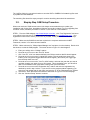
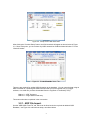

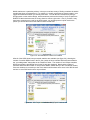
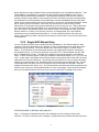

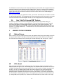
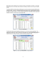

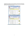

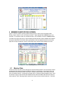

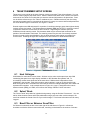


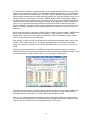

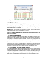


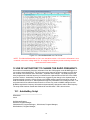

![Tester Bench [BETA] User Manual](http://vs1.manualzilla.com/store/data/005798606_1-651c3b6b51a13c0d6f27995a84bd9cc4-150x150.png)


![TR4W User Manual [English Version]](http://vs1.manualzilla.com/store/data/005798737_1-5ae60a1fb1429eafa2ca68266ac47e3b-150x150.png)


![TR4W User Manual [English Version]](http://vs1.manualzilla.com/store/data/005728234_1-e27c4fea1c6d513d6e0fdc1451ef66f1-150x150.png)