1
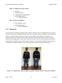
Department of Computer Science and Engineering The University of Texas at Arlington Team: Survivors Project: Sight By Touch Team Members: Gerardo Guevara Kevin Tran Victor Rodriguez Margaret Floeter Henry Loh Last Updated: 4/1/2014 System Requirements Specification Sight By Touch Table of Contents Table of Contents .........................................................................................................................................2 Document Revision History ........................................................................................................................5 List of Figures ..............................................................................................................................................6 List of Tables ...............................................................................................................................................7 1. Product Concept......................................................................................................................................8 1.1 Purpose and Use ..........................................................................................................................8 1.2 Intended Audience .......................................................................................................................8 2. Product Description and Functional Overview.....................................................................................10 2.1 Features and Functions ..................................................................................................................10 2.2 External Inputs and Outputs ...................................................................................................12 2.3 Product Interfaces ......................................................................................................................13 3. Customer Requirements........................................................................................................................14 3.1 On and Off .................................................................................................................................14 3.2 Detect Obstructions ...................................................................................................................15 3.3 Obstruction Notification ............................................................................................................15 3.4 Battery Powered.........................................................................................................................16 3.5 Inconspicuous Appearance ........................................................................................................16 3.6 Low Battery Notification ...........................................................................................................16 3.7 User Friendly .............................................................................................................................17 3.8 Maintainable ..............................................................................................................................17 3.9 Floor Depth Detection ...............................................................................................................17 4. Packaging Requirements ......................................................................................................................18 4.1 System Control Device ..............................................................................................................19 4.2 Sight By Touch System .............................................................................................................19 4.3 Battery........................................................................................................................................19 4.4 Charger ......................................................................................................................................20 4.5 Software .....................................................................................................................................20 4.6 User Manual...............................................................................................................................20 4.7 Cardboard Container ..................................................................................................................21 5. Performance Requirements ...................................................................................................................21 5.1 Switching Range Latency ..........................................................................................................21 April 1, 2014 2 Survivors System Requirements Specification Sight By Touch 5.2 Real-Time Response ..................................................................................................................22 5.3 Detection Quality .......................................................................................................................22 5.4 Vibration Intensity .....................................................................................................................23 5.5 Battery Life ................................................................................................................................23 5.6 Boot Up Time ............................................................................................................................23 6. Safety Requirements .............................................................................................................................24 6.1 Wearable Material .....................................................................................................................24 6.2 Exposed Circuitry Protection .....................................................................................................25 6.3 Power Supply Protection ...........................................................................................................25 6.4 Heat Dissipation.........................................................................................................................26 6.5 Water Resistance .......................................................................................................................26 6.6 Skin Irritation .............................................................................................................................26 6.7 Sensor Module Protection..........................................................................................................27 6.8 Static Electricity.........................................................................................................................27 7. Maintenance and Support Requirements ...............................................................................................27 7.1 Troubleshooting .........................................................................................................................27 7.2 Future Upgrades and Maintenance ............................................................................................28 7.3 Hardware Maintenance ..............................................................................................................28 7.4 Software Maintenance ...............................................................................................................28 8. Other Requirements ..............................................................................................................................29 8.1 Weight........................................................................................................................................29 8.2 Readability .................................................................................................................................30 8.3 Adjustable Range .......................................................................................................................30 9. Acceptance Criteria ..............................................................................................................................30 9.1 Verify that the System is intuitive and accessible .....................................................................31 9.2 Verify that the System help a visually impaired individual traverse around different environments..........................................................................................................................................31 9.3 Verify that the System Notifies the User That the Battery Is Low ............................................32 9.4 Verify That the System is safe to wear ......................................................................................32 9.5 Verify That the System Range is adjustable ..............................................................................33 10. Use Cases ............................................................................................................................................33 10.1 Turn System ON ........................................................................................................................34 April 1, 2014 3 Survivors System Requirements Specification Sight By Touch 10.2 Turn System OFF ......................................................................................................................34 10.3 Change Sensing Range ..............................................................................................................34 10.4 Use Case Diagram .....................................................................................................................35 11. Feasibility Assessment........................................................................................................................36 11.1 Scope Analysis...........................................................................................................................36 11.2 Research .....................................................................................................................................37 11.3 Technical Analysis.....................................................................................................................39 11.4 Cost Analysis .............................................................................................................................40 11.5 Resource Analysis .....................................................................................................................40 11.6 Schedule Analysis ......................................................................................................................41 12. Future Items ........................................................................................................................................44 12. 1 Requirement 3.9: Floor Depth Detection...................................................................................44 April 1, 2014 4 Survivors System Requirements Specification Sight By Touch Document Revision History Revision Revision Number Date Description Rationale 1.0 10/9/2013 First SRS Draft Team’s initial draft 1.1 11/6/2013 Added more content Based on feedback from BetaBlockers and Mike O’Dell 2.0 11/20/2013 SRS Baseline Based on feedback from SRS Gate Review 2.1 3/4/2014 SRS Baseline Update Revised and clarified a few requirements and concepts 2.2 4/1/2014 SRS Baseline Update 2 Upon referencing this document for the System Test Plan, inconsistencies were discovered between our intended scope and the scope reflected in this document, which were not caught during Baseline revision. These have been corrected. 5 Survivors April 1, 2014 System Requirements Specification Sight By Touch List of Figures Figure # Title Page # 2-1 Mock of the look of the suit 10 2-2 Sensors of the Sight By Touch System showed around the body 11 2-3 Closer look of a Sensor Module 11 2-4 Sketch of the System Control Unit 13 10-1 Use Case: Belt Operations 34 11-1 Spider Sense Suit developed by graduate students from the University of Illinois. 36 11-2 The suited being tested at the library. 37 11-3 Front and Rear of the Prototype 37 April 1, 2014 6 Survivors System Requirements Specification Sight By Touch List of Tables Figure # 2-1 Title Page # External Inputs and Outputs 12 11-1 Low and High End Cost of Components 39 11-2 Function Points 40 11-3 Influence Multipliers 41 11-4 Jones’ First Order Estimation 42 11-5 COCOMO II Model Estimation Tool 42 April 1, 2014 7 Survivors System Requirements Specification Sight By Touch 1. Product Concept This section describes the purpose, use and intended audience for the Sight By Touch system. The Sight By Touch system is made to aid visually impaired users through the use of vibrations. Users of the Sight By Touch system will be able to move around and gauge where they are. When a user walks near an object, the system will vibrate in the direction where the object is closest. This warns the user that there is an object nearby and thus prevents the user from colliding with the object. With the use of these vibrations created by the system, a visually impaired user will be able to avoid obstacles. 1.1 Purpose and Use The purpose of the Sight By Touch system is to aid visually impaired individuals since they are unable to rely on their sight. More often than not, visually impaired individuals require some form of aid to help guide them, usually through the use of a cane or training dog. Our team wishes to remove, or decrease, the dependence on the cane or training dog by allowing the user to be guided through vibrations from the system. In this way, the user’s hands will be free from not having to hold the cane or leash of a training dog so that the user will be able to use his hands for other purposes. With this system, a user should be able to avoid collision with any obstacles that are found in his environment. Our team has decided to make our system an indoor and outdoor system because we believe a visually impaired user will operate in both environments. The system should lead the user to a safe direction by warning the user when an object is within the radius of the sensors. The system does this through the use of vibrations from the vibration motors on the system. The vibration motors on the system will vibrate in the direction of the object when the sensors sense that the object is nearby. This system is used solely for the purpose of helping visually impaired users navigate in unknown surroundings or in familiar areas. This product is not intended to be used in a crowded place because there will be too much interference. 1.2 Intended Audience The intended audience for the Sight By Touch system are individuals who are visually impaired. We consider the visually impaired to be based on the following metrics provided by the American Optometric Association: 20/70 to 20/160 is considered moderate visual impairment, or moderate low vision 20/200 to 20/400 is considered severe visual impairment, or severe low vision 20/500 to 20/1,000 is considered profound visual impairment, or profound low vision April 1, 2014 8 Survivors System Requirements Specification Sight By Touch less than 20/1,000 is considered near-total visual impairment, or near total blindness no light perception is considered total visual impairment, or total blindness The system will come in one standard size, focused for individuals who are 5.6 to 6 feet tall, and the target group will be ages 14 through 25. Our main focus is individuals who are high school students and college students because these individuals do not like relying on the cane and would prefer something that would attract less attention. Since this is the intended range, accommodations for other target groups is currently not a priority. If a user is too tall or too short, the system will have to be customized. A user can also obtain this system from his or her counselor, who will order the system. The counselors or agencies that help the visually impaired individuals will be in charge of ordering the system because of their field of expertise. April 1, 2014 9 Survivors System Requirements Specification Sight By Touch 2. Product Description and Functional Overview This section provides the reader with an overview of the Sight By Touch system. The primary operational aspects of the system, from the perspective of the end users to the implementers of the back end, are defined here. The key features and functions found in the system, as well as critical user interactions and user interfaces, are described in detail. 2.1 Features and Functions The Sight By Touch system shall consist of an external belt that holds the main battery, which connects to the sensors and vibration motors. The batteries will be in a battery pack, which will be referred from now on as the battery. When the user is not using the product and wishes to charge the battery, the battery will be removed from the system so it can be charged. Figure 2-1: Mock of the look of the suit April 1, 2014 10 Survivors System Requirements Specification Sight By Touch The system will be a full blown suit, shown in Figure 2-1, with the sensors underneath the clothes and with their wires connected to the microcontroller. The sensors will be detachable to allow for flexibility and cleanliness. The scope of the system will be restricted to the front of the user (180 degrees, at least a 4 foot radius horizontally, and from the neck to the ankles vertically). When a sensor detects an object in its range, the sensor will send a signal to the microcontroller, which will then forward the message to the vibration motor. How close the object is will determine the intensity of the vibrations. The system will not be able to detect the absence of flooring such as a hole or a stair case. Figure 2-2: Sensors on the Sight By Touch System shown around the body April 1, 2014 11 Survivors System Requirements Specification Sight By Touch Figure 2-3: Closer look of a Sensor Module There will be multiple vibration motors distributed along the system, embedded in the suit. When the sensor connected to those vibration motors senses an object within the range, the sensor will send a signal to the microcontroller, which will then forward the message to the vibration motor. There can be multiple vibration motors vibrating at the same time and at different intensities depending on where the object is located. The closer the object is the more intense the vibration will be. In addition, depending on the location of the object being detected, the vibration motors closest to that object will vibrate the most. The system will also have an external belt (placed around the user’s waist) that will allow the user to interface with the device. The interface will have an on/off button to turn the sensors on/off. In addition, there will be a switch that allows the user to adjust the range that the sensors will detect. There will be no external elements for all the functions and data manipulation will be done internally. 2.2 External Inputs and Outputs The system will have a belt that contains a button which receives input from the user to turn the sensors on/off. Also the user will use a switch that will adjust the range of the sensor’s detection depending on what the user finds appropriate for the user's environment. The sensors will receive input which notifies the sensors that there is an object close by. With this data, the sensors will then communicate with the microcontroller, which then forwards the message to the vibration motors through signals. The vibration motors will take this input and intensify its vibration depending on the distance between the object and the sensors. Table 2-1: External Inputs and Outputs Name Description Power Button A button located on the belt part of the product. Turns the sensors on/off. Range Adjustor A switch located on the belt part of the product. Adjusts the range of the sensors. April 1, 2014 Use 12 Input: Initiated by the user when they are ready to use the product. Input: From the user when they wish to adjust the range of their sensors. Survivors System Requirements Specification Sight By Touch Proximity Sensor Used to detect objects nearby. Input: Sends messages to the microcontroller that an object has been detected. Vibration Motors Increases vibration as the distance of an object becomes closer. Output: Alerts the user in the form of a vibration. 2.3 Product Interfaces The system will have a control module that is placed on a belt. Once the belt is worn, the control module will be located in front of the user. The control module will have a button that turns the system on/off. The on/off button will have a slight elevation to determine what position the button is in. The control module will also have a switch that is capable of adjusting the system’s detection range. The body suit, which is the main part of the system, will have small sensor modules embedded in the suit and will face the front. On the front, there will be vibration motors distributed along the system. April 1, 2014 13 Survivors System Requirements Specification Sight By Touch Figure 2-4: Sketch of the System Control Unit 3. Customer Requirements This section consists of the requirements provided by our sponsor Jennifer Svelan must be implemented in order to provide a complete product. Each requirement will have a description, a source, constraints, standards, and a priority. The modification of any of the following requirements will require the approval of the sponsor. 3.1 On and Off April 1, 2014 14 Survivors System Requirements Specification Sight By Touch 3.1.1 Description: The system shall be able to be turned on/off by the push of a button. The user will be notified that the system was powered on. The preferred method of notification is through vibrations. 3.1.2 Source: Jennifer Svelan 3.1.3 Constraints: The duration of the notification and unobtrusive. 3.1.4 Standards: None 3.1.5 Priority: 1- Critical 3.2 Detect Obstructions 3.2.1 Description: The system shall be able to detect the presence of nearby objects that are in front and/or to the sides of the user that can impede the user from moving forward. The detection area of the system will need to cover at least a 4 foot radius in front of the user including the sides and vertically from the neck to the ankles. 3.2.2 Source: Jennifer Svelan 3.2.3 Constraints: The size and motion of objects, and quality of sensors. 3.2.4 Standards: none 3.2.5 Priority: 1 – Critical 3.3 Obstruction Notification 3.3.1 Description: The system shall be able to warn the user of the presence of nearby objects through the use of vibrations. The intensity of the vibrations felt by the user will correspond to the direction and the distance of the object(s) that the system has detected. 3.3.2 Source: Jennifer Svelan April 1, 2014 15 Survivors System Requirements Specification Sight By Touch 3.3.3 Constraints: The vibrations need to be strong enough to warn the user, but weak enough to prevent discomfort to the user. 3.3.4 Standards: none 3.3.5 Priority: 1 - Critical 3.4 Battery Powered 3.4.1 Description: The system shall be powered by a rechargeable battery. 3.4.2 Source: Jennifer Svelan 3.4.3 Constraints: The amount of power the system requires to operate. 3.4.4 Standards: none 3.4.5 Priority: 1 - Critical 3.5 Inconspicuous Appearance 3.5.1 Description: The system shall be as discrete as possible in order to attract the least amount of attention. 3.5.2 Source: Jennifer Svelan 3.5.3 Constraints: Position and size of the components. 3.5.4 Standards: None 3.5.5 Priority: 2 - High 3.6 Low Battery Notification 3.6.1 Description: The system shall be able to notify the user when the battery has less than an hour left of charge. 3.6.2 Source: Jennifer Svelan April 1, 2014 16 Survivors System Requirements Specification Sight By Touch 3.6.3 Constraints: The notification should be unobtrusive to the user and anyone around them. 3.6.4 Standards: None 3.6.5 Priority: 1 - Critical 3.7 User Friendly 3.7.1 Description: The system shall be user friendly so that anyone with or without sight can operate it. The functions will be intuitive and easy to learn. 3.7.2 Source: Jennifer Svelan 3.7.3 Constraints: The position of the system control module and operating difficulty of the system. 3.7.4 Standards: None 3.7.5 Priority: 2 – High 3.8 Maintainable 3.8.1 Description: The system shall have replaceable components that can be replaced by the distributor. Components that can be replaced include the sensor modules and the battery. Any faulty components will be able to be replaced without the need to purchase an entirely new system. 3.8.2 Source: Jennifer Svelan 3.8.3 Constraints: Modularity of the components 3.8.4 Standards: None 3.8.5 Priority: 4 – Low 3.9 Floor Depth Detection 3.9.1 Description: The system shall be able to detect the depth of the floor. When appropriate, the system must be able to detect that there is no proper footing for the user, which could mean a flight of stairs or a hole in the ground. 3.9.2 Source: Jennifer Svelan April 1, 2014 17 Survivors System Requirements Specification Sight By Touch 3.9.3 Constraints: None 3.9.4 Standards: None 3.9.5 Priority: 5 – Future 4. Packaging Requirements This section will list and describe each major component of the system. These components include hardware, software and documentation that will be delivered to the user. The system will be packaged with a “Plug-and-Play” type setup. The system itself will be broken into two parts which is the suit and the system control device. The sensor modules will come attached to the suit and the system control device will come attached to the external belt. The sensor modules will be composed of distance sensors April 1, 2014 18 Survivors System Requirements Specification Sight By Touch and vibration motors. The software will be pre installed in the system control device, so all that is required of the user is to connect the system control device to the suit and then the battery before using the system. The battery will be included in the package, but not connected to the system to avoid any harm to the system. The package will contain a charger, but will not contain any extra parts. 4.1 System Control Device 4.1.1 Description: The package shall include a device that will allow the user to control and power the system. 4.1.2 Source: Survivors 4.1.3 Constraints: The device will require a power source. 4.1.4 Standards: None 4.1.5 Priority: 1 - Critical 4.2 Sight By Touch System 4.2.1 Description: The package shall include the Sight By Touch System with all of the sensor modules (sensors and vibration motors) embedded in the suit. 4.2.2 Source: Survivors 4.2.3 Constraints: The system will require a power source. 4.2.4 Standards: None 4.2.5 Priority: 1 – Critical 4.3 Battery 4.3.1 Description: The system shall come with its own rechargeable power source. 4.2.2 Source: Survivors 4.3.3 Constraints: Power source must last between 6-10 hours from a full charge. 4.3.4 Standards: None April 1, 2014 19 Survivors System Requirements Specification Sight By Touch 4.3.5 Priority: 1 – Critical 4.4 Charger 4.4.1 Description: The package shall include a charger that will be used to recharge the battery. 4.4.2 Source: Survivors 4.4.3 Constraints: Power source must last between 6-10 hours. 4.4.4 Standards: None 4.4.5 Priority: 1 - Critical 4.5 Software 4.5.1 Description: The system shall come with the software pre-installed. 4.5.2 Source: Survivors 4.5.3 Constraints: None 4.5.4 Standards: None 4.5.5 Priority: 1 – Critical 4.6 User Manual 4.6.1 Description: The package shall include a user manual (a printed copy and an Audio CD) with instructions on how to wear and use the system. 4.6.2 Source: Survivors 4.6.3 Constraints: None April 1, 2014 20 Survivors System Requirements Specification 4.7 4.6.4 Standards: None 4.6.5 Priority: 3 – Moderate Sight By Touch Cardboard Container 4.7.1 Description: The package shall consist of a 2 x 2 x 2 cardboard box. The Sight By Touch System, system control device, manual, battery, and charge will be packaged inside their individual package inside the cardboard box. 4.7.2 Source: Survivors 4.7.3 Constraints: None 4.7.4 Standards: None 4.7.5 Priority: 3 - Moderate 5. Performance Requirements This section covers the performance requirements the system must fulfill by specifying how well the system functions overall. Performance requirements will address the quality, coverage and timeliness of our system. 5.1 Switching Range Latency April 1, 2014 21 Survivors System Requirements Specification Sight By Touch 5.1.1 Description: The system shall be able to switch between any of the predefined ranges in less than 2 seconds. Please see Requirement 8.3 for the predefined ranges. 5.1.2 Source: Survivors 5.1.3 Constraints: Performance of the microcontroller. 5.1.4 Standards: None 5.1.5 Priority: 2 - High 5.2 Real-Time Response 5.2.1 Description: The system shall be able to detect objects and notify the user through vibrations between 30 milliseconds to 100 milliseconds. 5.2.2 Source: Survivors 5.2.3 Constraints: Quality of microcontroller(s), the processing algorithm, and the environment. 5.2.4 Standards: None 5.2.5 Priority: 1 – Critical 5.3 Detection Quality 5.3.1 Description: The system shall be able to detect objects within 10 feet max. 5.3.2 Source: Survivors 5.3.3 Constraints: Quality of the distance sensors. 5.3.4 Standards: None April 1, 2014 22 Survivors System Requirements Specification Sight By Touch 5.3.5 Priority: 1 - Critical 5.4 Vibration Intensity 5.4.1 Description: The system shall have a safe vibration intensity of 0.063 m/s2 to 1.15 m/s2. This range ensures that the system can warn the user without harming the user. 5.4.2 Source: Survivors 5.4.3 Constraints: Quality of the vibration motors. 5.4.4 Standards: None 5.4.5 Priority: 1- Critical 5.5 Battery Life 5.5.1 Description: The rechargeable battery shall last between 6-10 hours on full recharge cycles. 5.5.2 Source: Survivors 5.5.3 Constraints: Power source, distance sensors, vibration motors, and microcontroller 5.5.4 Standards: None 5.5.5 Priority: 2 - High 5.6 Boot Up Time 5.6.1 Description: The system shall start up in no more than 5 seconds. 5.6.2 Source: Survivors 5.6.3 Constraints: None 5.6.4 Standards: None April 1, 2014 23 Survivors System Requirements Specification 5.6.5 Sight By Touch Priority: 2 – High 6. Safety Requirements This section covers the safety requirements the system must fulfill. These requirements will cover the safety of both the system and the user. The system must be safe in all aspects regarding hardware, software and the user’s safety. 6.1 Wearable Material April 1, 2014 24 Survivors System Requirements Specification Sight By Touch 6.1.1 Description: The system shall not contain materials that could jeopardize the user’s health including, but not limited to: conductive material, allergic material, sharp objects, rusted material, etc. 6.1.2 Source: Survivors 6.1.3 Constraints: None 6.1.4 Standards: None 6.1.5 Priority: 2 - High 6.2 Exposed Circuitry Protection 6.2.1 Description: The system shall have no exposed wires or electrical components that will directly come into contact with the user’s skin. 6.2.2 Source: Survivors 6.2.3 Constraints: None 6.2.4 Standards: None 6.2.5 Priority: 1- Critical 6.3 Power Supply Protection 6.3.1 Description: The system shall keep the power supply covered by a material that provides protection from any possible power leaks (ex. chemical, electrical, battery meltdown, etc.) 6.3.2 Source: Survivors 6.3.3 Constraints: Prevent heat build-up. April 1, 2014 25 Survivors System Requirements Specification Sight By Touch 6.3.4 Standards: None 6.3.5 Priority: 1- Critical 6.4 Heat Dissipation 6.4.1 Description: The system shall dissipate heat produced by the components of the system to prevent overheating. 6.5 6.4.2 Source: Survivors 6.4.3 Constraints: Location of components. 6.4.4 Standards: None 6.4.5 Priority: 1- Critical Water Resistance 6.5.1 Description: The system shall be water resistant to light rain (precipitation rate less than 2.5 millimeters (0.098 in) per hour). This also includes sweat (32-48oz of fluid per hour). 6.6 6.5.2 Source: Survivors 6.5.3 Constraints: Components resistance to water. 6.5.4 Standards: None 6.5.5 Priority: 1- Critical Skin Irritation 6.6.1 Description: The system shall not irritate the skin of the user. Vibrations should be kept at a safe range to avoid harming the skin of the user. 6.6.2 Source: Survivors 6.6.3 Constraints: None 6.6.4 Standards: None April 1, 2014 26 Survivors System Requirements Specification 6.6.5 6.7 Sight By Touch Priority: 1- Critical Sensor Module Protection 6.7.1 Description: The system shall keep the sensor module components inside an enclosure to prevent any harm to the user as well as any damage to the components. 6.8 6.7.2 Source: Survivors 6.7.3 Constraints: Size of the sensor module components. 6.7.4 Standards: None 6.7.5 Priority: 1- Critical Static Electricity 6.8.1 Description: The system shall not produce static electricity that would harm the user, the system and anybody that comes into contact with the user 6.8.2 Source: Survivors 6.8.3 Constraints: None 6.8.4 Standards: None 6.8.5 Priority: 2 - High 7. Maintenance and Support Requirements This section will list and describe the maintenance and support that will be provided for the delivered system. This includes documentation and maintenance. 7.1 Troubleshooting April 1, 2014 27 Survivors System Requirements Specification Sight By Touch 7.1.1 Description: The system shall include a troubleshooting guide to identify problems and recommend possible solutions. 7.2 7.1.2 Source: Survivors 7.1.3 Constraints: None 7.1.4 Standards: None 7.1.5 Priority: 2 - High Future Upgrades and Maintenance 7.2.1 Description: The team will not be responsible for future upgrades and maintenance after the due date of the project. 7.3 7.2.2 Source: Survivors 7.2.3 Constraints: None 7.2.4 Standards: None 7.2.5 Priority: 3 – Moderate Hardware Maintenance 7.3.1 Description: The team shall provide documentation and hardware details to aid future development teams and users to allow them to extend our product. 7.4 7.3.2 Source: Survivors 7.3.3 Constraints: None 7.3.4 Standards: None 7.3.5 Priority: 3 - Moderate Software Maintenance 7.4.1 Description: The team shall provide documentation and source code to aid future development teams and users to allow them to extend our product. 7.4.2 Source: Survivors 7.4.3 Constraints: None April 1, 2014 28 Survivors System Requirements Specification 7.4.4 Standards: None 7.4.5 Priority: 3 - Moderate Sight By Touch 8. Other Requirements This section includes requirements not previously mentioned in other sections of the document. The addition of these requirements will be needed in order for the product to be deemed complete. 8.1 Weight 8.1.1 April 1, 2014 Description: The entire system shall be weight under six pounds. 29 Survivors System Requirements Specification 8.2 Sight By Touch 8.1.2 Source: Survivors 8.1.3 Constraints: Weight of the battery, wires, sensor modules and system control module. 8.1.4 Standards: None 8.1.5 Priority: 3 – Moderate Readability 8.2.1 Description: The system shall have braille next to the on/off button and the sensory range to improve utility for the visually impaired. 8.3 8.2.2 Source: Survivors 8.2.3 Constraints: None 8.2.4 Standards: None 8.2.5 Priority: 3 – Moderate Adjustable Range 8.3.1 Description: The system shall be able to allow the user to select from the predefined max range radius of 4 or 10 feet. 8.3.2 Source: Survivors 8.3.3 Constraints: Performance of the system’s sensors and microcontroller 8.3.4 Standards: None 8.3.5 Priority: 2 – High 9. Acceptance Criteria This section includes every requirement that will be verified by the sponsor. Each feature and function must be demonstrated to the sponsor until the sponsor is satisfied. After the sponsor is satisfied, the sponsor will be able to accept or reject the system. To avoid any legal issues, a member of the team will volunteer to test the system for the verification process. April 1, 2014 30 Survivors System Requirements Specification 9.1 Sight By Touch Verify that the System is intuitive and accessible 9.1.1 Requirement(s) addressed: 3.1 On and Off: The system shall be able to be turned on/off by the push of a button. 3.4 Battery Powered: The system shall be powered by a rechargeable battery 3.7 User Friendly: The system shall be user friendly so that anyone with or without sight can operate it. The functions will be intuitive and easy to learn. 5.6 Boot Up Time: The system shall start up in no more than 5 seconds. 8.2 Readability: The system shall have Braille next to the on/off button and the sensory range to improve utility for the visually impaired. 9.1.2 Verification Procedure: The system will be displayed so that the sponsors can freely inspect the system. Then a small demonstration will be presented to the sponsor that will cover introductory topics such as how to wear the system, the layout of the controls, turn the system on/off, and how to change the range of detection. 9.2 Verify that the System help a visually impaired individual traverse around different environments 9.2.1 Requirement(s) addressed: April 1, 2014 3.2 Detect Obstructions: The system shall be able to detect the presence of nearby objects that are in front and/or to the sides of the user. The detection area of the system will need 31 Survivors System Requirements Specification Sight By Touch to cover at least a 4 foot radius in front of the user including the sides and vertically from the neck to the ankles. 3.3 Obstruction Notification: The system shall be able to warn the user of the presence of nearby objects through the use of vibrations. The vibration’s felt by the user will correspond to the direction and the distance of the object(s) that the system has detected. 5.2 Real-Time Response: The system shall be able to detect objects and notify the user through vibrations between 30 milliseconds to 100 milliseconds. 5.3 Detection Quality: The system shall be able to detect objects within 10 feet max. 5.4 Vibration Intensity: The system shall have a safe vibration intensity of 0.063 m/s2 to 1.15 m/s2. This range ensures that the system can warn the user without harming the user. 9.2.2 Verification Procedure: The team shall demonstrate how the system helps visually impaired individuals by blindfolding a volunteer and then having the volunteer navigate through different courses that simulate different environments. 9.3 Verify that the System Notifies the User That the Battery Is Low 9.3.1 Requirement(s) addressed: 3.6 Low Battery Notification: The system shall be able to notify the user when the battery has less than an hour left of charge. 6.3 Power Supply Protection: The system shall keep the power supply covered by a material that provides protection from any possible power leaks (ex. chemical, electrical, battery meltdown, etc.) 9.3.2 Verification Procedure: The team will install a very low charged battery into the system and then will ask the user if they feel the “Low Battery Vibrations”. 9.4 Verify That the System is safe to wear 9.4.1 Requirement(s) addressed: April 1, 2014 6.1 Wearable Material: The system shall not contain materials that could jeopardize the user’s health including, but not limited to: conductive material, allergic material, sharp objects, rusted material, etc. 32 Survivors System Requirements Specification Sight By Touch 6.2 Exposed Circuitry Protection: The system shall have no exposed wires or electrical components that will directly come into contact with the user’s skin. 6.4 Heat Dissipation: The system shall dissipate heat produced by the components of the system to prevent overheating. 6.5 Water Resistance: The system shall be water resistant to light rain (precipitation rate less than 2.5 millimeters (0.098 in) per hour). This also includes sweat (32-48oz of fluid per hour). 6.6 Skin Irritation: The system shall not irritate the skin of the user. Vibrations should be kept at a safe range to avoid harming the skin of the user. 6.8 Static Electricity: The system shall not produce static electricity that would harm the user, the system, and anyone who comes into contact with the user. 9.4.2 Verification Procedure: The team will submit a detail report about the capabilities and limitations of the system to the sponsor. Then during the demonstration, one of the team members will wear the suit while simulating different conditions such as light rain by using a spray bottle. Then the team will allow any other individual interested in trying the product for about 15 minutes and then asking the user if they feel any discomfort. 9.5 Verify That the System Range is adjustable 9.5.1 Requirement(s) addressed: 8.3 Adjustable Range: The system shall be able to allow the user to select from the predefined max range radius of 4 or 10 feet. 5.1 Switching Range Latency: The system shall be able to switch between any of the predefined ranges in less than 2 seconds. Please see Requirement 8.3 for the predefined ranges. 9.5.2 Verification Procedure: A volunteer will put the system on and then will adjust the range by flipping the switch. As the volunteer flips the switch we will move an object in and out of the range to show that the range has truly been adjusted to 4 or 10 feet. 10. Use Cases April 1, 2014 33 Survivors System Requirements Specification Sight By Touch This section includes the identified Use Cases and Use Case Diagram. The Use Cases are Turn the System ON, Turn the System OFF, and Change Range. These Use Cases belong to one system, which is the Sight By Touch system. Below are the high level uses cases for the project. Note TUCBW stands for “This Use Case Begins With” and TUCEW stands for “This Use Case Ends With”. 10.1 Turn System ON 10.1.1 Precondition: The System is OFF, and battery is connected 10.1.2 Scenario: The User turns ON the system 10.1.3 Actor: User 10.1.4 System: Sight By Touch 10.1.5 TUCBW: The user presses the power button 10.1.6 TUCEW: The user feels the initial vibration of the system 10.2 Turn System OFF 10.2.1 Precondition: The System is ON 10.2.2 Scenario: The User turns OFF the system 10.2.3 Actor: User 10.2.4 System: Sight By Touch 10.2.5 TUCBW: The user presses the power button 10.2.6 TUCEW: The user will feel two strong vibrations 10.3 Change Sensing Range April 1, 2014 34 Survivors System Requirements Specification Sight By Touch 10.3.1 Precondition: The System is ON 10.3.2 Scenario: User wants to extend or shorten the sensing range by flipping the switch 10.3.3 Actor: User 10.3.4 System: Sight By Touch 10.3.5 TUCBW: The user flips the switch 10.2.6 TUCEW: The user feels that the switch’s position has changed 10.4 Use Case Diagram Figure 10-1 Use Case: Belt Operations April 1, 2014 35 Survivors System Requirements Specification Sight By Touch 11. Feasibility Assessment This section includes the six components (scope analysis, research completed/remaining, technical analysis, cost analysis, resource analysis, and schedule analysis) that we used to determine if the team could implement the project. 11.1 Scope Analysis After analyzing the scope and multiple discussions about the complexity of the product and budget, we have concluded that completing an entire commercial system is not feasible. However, all of the critical requirements are reasonable, and prototyping of these by the deadline date appears feasible. We expect that three requirements will be the main bulk of our system, which is the ability of the system to correctly detect objects and notifying the user through vibrations while keeping a compact design. Many of the requirements have a high priority, which is why we have broken down the priorities of the system based on the level of impact that the requirement would cause if it was not implemented. To ensure that the priorities are reflected in the implementation phase we are going to develop the system in an incremental approach (phase development) in order from high to low priority. Our goal will be to at least complete 75% of Phase 3, and if time and budget allows, finish all of Phase 3 and possibly Phase 4. To ensure that we meet our safety requirements we will consider every safety requirement at every phase, which means that our implementation will be driven by the safety requirements. The phases will be completed in a waterfall process so we are not going to move on until the previous phase is completed. Phase 1 (Core functionality) Detect Obstructions Collision Prevention Battery Powered Low Battery Notification Safety Requirements Skin Irritation Power Supply Protection Exposed Circuitry Protection Phase 2 (Physical Structure) April 1, 2014 Safety Requirements Previous Requirements Water Resistance Static Electricity Heat Dissipation Wearable Material Sensor Module Protection 36 Survivors System Requirements Specification Sight By Touch Phase 3 (Complete Prototype system) ON/OFF Adjustable Range Common Physical Appearance Safety Requirements All Requirements Phase 4 (Future Capabilities) Floor Depth Detection Safety Requirements Not Yet Identified 11.2 Research The team has been looking at graduate projects that are similar to the core functionality of our system. One of these projects is called the “Spider Sense Suit” from the University of Illinois. The suit has 360 degree coverage around by placing 11 distance sensor modules. Each module is composed of a ultrasonic range sensor and servo motor, that scans the environment and warns the user of possible obstacles by exerting pressure to the skin via the servo motor’s arm. The suit currently has a primitive design and was not built for the visually impaired. However, based on the capabilities and current test reported by the graduate students, we are more optimistic about the feasibility of the project. Figure 11-1: Spider Sense Suit developed by graduate students from the University of Illinois. April 1, 2014 37 Survivors System Requirements Specification Sight By Touch Figure 11-2: The suited being tested at the library. The next project was created at the New Jersey Institute of Technology for the purpose of aiding the blind as a secondary electronic device that can be used with a cane. The project uses a similar concept as our project of using proximity sensors and warns the user though vibrations with the ability to adjust the sensing range. However, some key differences are that this device only provides chest coverage, only has constant vibrations that do not let the user gauge the distance to the object. This device will be used as a secondary device, and is mounted on suspenders. Overall, the idea of using proximity sensors to detect objects and using vibrations to warn the user is now more realistic since it has been done before. Figure 11-3: Front and Rear of the Prototype Another area the team has done research on has been on the backup systems that vehicles currently use. The team discovered that these systems do much of the processing and detection that our system needs. The Sight By Touch system could mimic what a backup car system does, which could mean that a good portion of our hardware could be assembled without having to modify the original component. In terms of cost, many of these systems can be purchased for less than $100. Besides sensing systems, the team has also researched the individual components such as batteries, distance sensors, vibration motors, and microcontrollers. So far we have discovered that we have a vast amount of possible combinations that will allow us to complete the system. Based on the different component specifications, we noticed that our system would have to address a lot of the safety April 1, 2014 38 Survivors System Requirements Specification Sight By Touch requirements such as heat, static electricity, buzzing sounds (due to the frequency of the vibration motors), and level of water resistance. Other areas that we still need to do research on are how the system could be worn so that the user can easily use the system without having the system intrude in their daily activities. So far we have decided to create a suit that is worn below normal clothes. However, we still need to make sure that the clothes do not interfere with the sensor and the issue of how to clean the suit would also have to be addressed. 11.3 Technical Analysis Technical aspects of our project will include compact design, algorithm implementation, and embedded system. We recognize that the team does not have a strong set of hardware skills, which is why we have identified that retrieving the signal of the sensor while keeping a compact design will be the hardest part of the project. Our system will require us to convert between analog and digital signals very quickly in a limited computational environment while keeping the system at a compact and wearable level. We understand that the system will be portable, so we have to make sure that the overall design is as compact as possible. To aid us we have the support of our two sponsors (Paul and Jennifer) who together can give us some guidance from a technical and a user perspective of the system. Our sponsor will help the team keep a balance between designing a compact design and the core functionality so that our project can address both concerns. Also, we have the support of other development teams that can provide ideas and concerns that can guide our design. To make sure that this project is successful, the skills required by the team will be to understand how to interact directly with sensors and vibration motors, designing skills, and efficient software implementations. Many of the core functionalities of the system require that the input can be clearly received and delivered in an appropriate time interval so that the system can warn the user in time. On top of that, the system needs to be able to be worn by a visually impaired user which means that coming up with a compact design is difficult since the less pieces the better. We have discovered that similar systems currently exist and that we may be able to use their hardware design and components to fulfill the requirements. We have found that many of the components can be bought prebuilt and even have similar interfaces that will help the team during the development phase. In terms of programming, the team understands that the system will mostly use a low level language, but the team will try to find a microcontroller that can be programmed in C. April 1, 2014 39 Survivors System Requirements Specification Sight By Touch 11.4 Cost Analysis Based on the team’s judgment and current research, we predict that we will be able to complete this project with an $800 budget. Most of the hardware components are available to buy from several vendors. This gives us a lot of flexibility in terms of choosing between the accuracy and cost of the overall system. Overall, our budget will determine the effective range and the performance of the system. Below is a summary of what the cost will be for some of the components. Table 11-1: Low and High End Cost of Components Items Quantity Low End Unit Price Vibration Motors 8-10 $1 $5 $15 Battery 1-4 $5 $10 $15 Proximity Sensors 8-10 $2 $30 $50 Microcontroller 1-2 $2 $100 $250 $54 $590 $1180 Total Expected Unit Price High End Unit Price The table above summarizes some of the components that our system will need to have. We have three columns, where the first is the quantity that we expect to use of each component; the second column lists the price for a low end component; the third list the price for a higher end component. Based on the price of some components we realize that it will not be possible to use the best so we will need to find the right balance of quality and price. 11.5 Resource Analysis The team has 2 software engineers (Victor, Gerardo), 2 computer science members (Kevin, Margaret), and 1 computer engineer (Henry). Henry will be in charge of the hardware implementation and physical communication between the components. Victor and Margaret will be in charge of developing the software for the system. Gerardo and Kevin will be in charge of the integration between the software and hardware. April 1, 2014 40 Survivors System Requirements Specification Sight By Touch 11.6 Schedule Analysis To estimate the schedule, the team has used multiple estimation techniques. We chose to use function points, Jones First Order Estimation, and COCOMO II to provide an initial estimate. Other techniques may be used in the future for additional estimates that will give us a better idea of the schedule. Table 11-2: Function Points Function Type Low Complexity Medium Complexity High Complexity Functional Point Total inputs 2*3 1*4 1*6 16 outputs 0*4 0*5 2*7 14 Inquiries 2*3 1*4 0*6 10 Logical internal files 0*7 0*10 1*15 15 External interface files 0*5 0*7 0*10 0 Unadjusted Total 55 Adjustment Factor 1.09 Adjusted Total 59.95 The above table show the complexity of our system based on the business functionality to the user. To understand the graph better here are some definitions: Inputs: Information that comes from outside the application to inside the application boundary Outputs: Information that crosses the boundary from inside to outside the application boundary that contains derived information. Inquiries: Information that crosses the boundary from inside to outside the application boundary that does not contain derived information. Logical internal files: A user identifiable group of logically related data that resides entirely within the applications boundary and is maintained through external inputs April 1, 2014 41 Survivors System Requirements Specification Sight By Touch External interface files: A user identifiable group of logically related data that is used for reference purposes only Table 11-3: Influence Multipliers Influence Multipliers Characteristics Effort (0-5) Data Communications 4 Distributed Data Processing 3 Performance 5 Heavily Used Configuration 2 Transaction Rate 5 Online Data Entry 0 End User Efficiency 5 Online Update 0 Complex Processing 5 Reusability 2 Installation Ease 5 Operation Ease 5 Multiple Sites 0 Facilitate Change 3 Total 44 Value Adjustment Factor 1.09 The formula used to derive the Value Adjustment Factor was (Total *.01) + .65. Based on these multipliers we can adjust the value of the function points, so that the Jones’ First Order Estimation results can be as accurate as possible. April 1, 2014 42 Survivors System Requirements Specification Sight By Touch Table 11-4: Jones’ First Order Estimation Best Case Average Case Worst Case 59.95.43 59.95.45 59.95.48 5.81 Calendar Months 6.31 Calendar Months 7.13 Calendar Months Based on the results from Jones’ First Order Estimation, we feel that we have plenty of time to implement the project. However, something that we need to understand is that this estimation is based on the amount of business logic that the project needs to address, so many of the hardware complexity may not be addressed by this estimation. However, we can simplify the hardware of the prototype during the Architecture Design in case that we notice that a compact design is not achievable. Table 11-5: COCOMO II Model Estimation Tool Optimistic 6.7 Months Most Likely 7.6 Months Pessimistic 8.6 Months COCOMO II was another method that we used to estimate the duration of the project. We noticed that the expected duration of the project increases dramatically, but this is due to the high estimation of the expected source lines of code (estimated about 3000 SLOC). The model we chose was the early design model because we don’t have many requirements that the other models asked of us. After analyzing the results of the schedule estimation and all of the previous analysis, we are certain that this project is feasible. However, we understand that we need to make sure that as we progress through the project, we keep in mind that this can quickly change if we are not careful with the future addition of requirements. April 1, 2014 43 Survivors System Requirements Specification Sight By Touch 12. Future Items This section reiterates requirements that were listed as priority 5 in previous requirement sections that were intended for the future. These requirements were suggested by the sponsor and, if more time is allowed, may be considered in future enhancements. 12. 1 Requirement 3.9: Floor Depth Detection 12.1.1 Requirement Description: Unleveled areas, such as stairs or holes made in the ground, specified in Customer Requirement 3.9: The system shall be able to detect the depth of the floor. 12.1.2 Constraint: Schedule: The main focus is to implement sensors that sense objects in front of a user. If time allows, we will work to make the sensors detect objects in unleveled environments to avoid injury to the user. April 1, 2014 44 Survivors


![[Product Monograph Template - Standard]](http://vs1.manualzilla.com/store/data/005786637_1-bbde87d0b5b85ef8c8ff6a7fd943fd08-150x150.png)