1
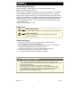
Solutions for Demanding Applications VARTECH SYSTEMS I N C. XHBL Series 8.4” – 10.4” – 12.1” – 15.1” User’s Guide Read instructions completely before attempting to operate your Display Information Disclaimer This VarTech Systems Inc. publication is provided “as-is”, without warranty of any kind, either expressed or implied, including but not limited to the implied warranties or merchantability and fitness for a particular purpose. Documentation Change Notice The information in this publication is subject to change without prior notice in order to improve readability and reliability as well as design and function. These changes shall be incorporated in a new revision, available from the product and/or download section of the VARTECH web site, www.vartechsystems.com. Liability In no event shall VARTECH be liable for direct, indirect, special incidental or consequential damages arising out of the use of or the inability to use VARTECH’s product or its documentation, even if advised of the possibility of such damages. Endorsement Product names mentioned herein are used for identification purposes only and may be trademarks and/or registered trademarks of their respective companies. Copyright This document contains proprietary information protected by copyright. All rights are reserved. No part of this manual, in whole or part, may be reproduced by any means, in any form, without prior written permission of Vartech Systems Inc. WM Table of Contents Safety ..................................................................................... 4 Product Care and Maintenance.................................................... 6 System Set-up ........................................................................ 8 Installation ............................................................................. 9 Cable Connections .................................................................. 11 Optional AC Power Adapter...................................................... 12 Computer Hook-up .................................................................. 13 Operator Controls.................................................................... 15 On-Screen Display (OSD) ......................................................... 16 Optional Internal Heater ........................................................... 20 Optional NVIS Filter ................................................................. 21 Optional USB Pass-through Connector ....................................... 21 Optional Touch Screen Display.................................................. 22 Appendix A - Mechanical Drawings ........................................... 30 Appendix B - Troubleshooting ................................................... 30 Appendix C - NEMA and IP Industry Standards ........................... 32 Appendix D - Technical/Environmental Specifications................... 33 SAfETy General Safety Instructions • Before operating the XHBL Monitor, read this User Manual thoroughly • Keep this User Manual for future use • Verify computer capability (see System Set-up) to insure operation of the Monitor • For expeditious installation, follow these User Manual instructions in sequence • Adhere to all Caution and Warnings on system and as stated in this User Manual • User Manual instructions for installation and operation should be followed precisely • Adjust only those controls covered by the User Manual’s operating instructions; improper adjustment of other controls voids the unit’s warranty and may result in unit damage, and • Adhere to local installation codes. Safety Icons Warning! Shock Hazards This icon is intended to tell the User of a potential risk of electrical shock. warning! Caution! Instructional This icon is intended to tell the User of important operating and/or maintenance instructions. caution! General Unit Safety • • • • • • Always disconnect the unit from the power source before cleaning Do not operate the unit with a damaged cord Do not operate if the unit has been dropped or damaged. The unit should be inspected by qualified VARTECH Service Personnel Position the power cord so it is not in contact with hot surfaces Do not allow anything to rest on the power cord, and Do not place the power cord in the path of foot traffic. General Safety Precautions warning! • • • • • • Power cord must be connected to a properly wired and grounded power source Any equipment to which the unit is attached must also be connected to properly wired and grounded power sources Do not connect or disconnect the unit during an electrical storm Do not remove the unit covers – there are no user serviceable parts in the unit Do not disassemble or modify the unit to avoid the possibility of electrical shock, damage to electrical components or scratching the display surface, and Disassembly of the unit voids the warranty. XHBL Series 4 150-120 fluids from LCD Display caution! • • If the Monitor should ever become shattered, do not touch fluids from the LCD display If fluid should get on hands or clothing, immediately wipe off with liquid soap or rubbing alcohol on a clean towel; wash with water; immediately consult with a doctor, and • If fluid gets in the eyes, flush eyes immediately with water for a minimum of 15 minutes; immediately consult with a doctor. Electrical Connecting Cables • • Disconnect the power to the computer when the Monitor is being installed, and Upon installation, verify the power connector is securely seated on the unit. Power Source This unit may be operated from an AC (optional) or DC (standard) power source. • Use the supplied power cable, and • Always connect to a properly grounded power source. EMI/RfI caution! This product has been engineered to meet or exceed international industry standards addressing product design and enclosure protection against EMI/RFI when installed with the factory provided cables. Protection on Servicing Servicing - User • • User product servicing is limited to cleaning the unit Do not disassemble or modify the unit to avoid the possibility of electrical shock, damage to its electrical components or scratching the display surface, and • Disassembly voids the warranty. Servicing VARTECH Qualified Service Personnel may be required if the unit: • Does not operate normally when installation instructions are followed • Does not operate normally when operating instructions are followed • Has been dropped or damaged, or • Exhibits a distinct change in performance, indicating a need for service. Shipping If the unit should need to be shipped to the VARTECH Service Center, the original packing material should be used to insure safety of the unit in shipping. Repack the unit as it would have originally been received from VARTECH. 6 XHBL Series 5 150-120 PRODUCT CARE AND MAINTENANCE Product Care This XHBL Monitor has been designed to provide optimum performance and service without any required scheduled maintenance other than occasional cleaning. Disconnect the Monitor from the power source before cleaning the Monitor, optional Touch Screen or unit’s enclosure. warning! • Do not use abrasive cleaners or solvent-based (flammable) cleaners on the Flat Panel or Touch Screen Display, its enclosure or any other electrical device (cables, power cord, etc.) • Do not use paper products as they may scratch the display screen, and • Do not directly apply cleaning solutions to the display screen. caution! Display Screen Cleaning • A vinegar-based cleaner is preferred to prevent streaking and degradation of the coatings, or • A non-abrasive glass cleaner such as a professional foam glass cleaner • Apply the cleaning solution to a soft clean cloth, dampening slightly • Keep a fresh side of the cleaning cloth towards the screen surface to avoid scratching it with accumulated grit, and • To minimize the risk of abrasion to the screen, air drying is recommended. In marine or similar environments, an added benefit of a vinegar-based cleaner is its effectiveness in dissolving mineral and salt deposits. Optional Touch Screen warning! The Touch Screen Display may be activated when cleaning. This may create a potentially dangerous condition: power down; disconnect cabling prior to cleaning. Touch Screen Cleaning • Use a special screen cleaning tissue or a solution specifically formulated for antistatic coatings. Follow the manufacturer’s instructions, or • Lightly dampen a soft clean cloth with water or a general purpose mild detergent solution • Keep a fresh side of the cleaning cloth towards the screen surface to avoid scratching it with accumulated grit, and • To minimize the risk of abrasion to the screen, air drying is recommended. Monitor Enclosure • Clean the unit enclosure with a soft clean cloth lightly dampened with a general purpose mild detergent solution • Wipe down with clean water, and • Dry with a soft clean cloth. XHBL Series 7 6 150-120 Long-term Storage • For long-term storage, it is suggested the unit be stored in a normal indoor environment and the display glass be protected from accidental damage • For pedestal mount units, disconnect the cable(s) and loosen the arm adjustment to a point where the ball can be removed from the arm, or • For Flush or Panel Mount units, cover the product with a protective covering that will not scratch or transfer any dyes to the display screen. Maintenance Power Cord warning! To avoid shock and fire hazards, replaced the unit’s power cord if: • Insulation becomes damaged, or • A loose connection is suspected. Other Maintenance Only VARTECH Qualified Service Personnel should perform all other maintenance except for cleaning and the power cord replacement described above. warning! XHBL Series To avoid risk of electrical shock, do not disassemble the unit’s enclosure. Users cannot service the Monitor. User maintenance is restricted to cleaning or power cord replacement as explained. Disassembling the unit voids the warranty. 7 150-120 SYSTEM SET-UP System Requirements The computer the XHBL is connected to must have this capability: • Video card setting with a minimum resolution of 640 x 480 pixels, and • If the optional Touch Screen Display is ordered, an available COM or USB port for the connector is required, depending on the display connector style ordered. Shipping Box Contents The XHBL is shipped in a custom box with custom foam packaging. It is recommended the installer save the box and all packaging materials in case the unit would need to be returned to the VARTECH Service Center. The shipping box contents are: • XHBL unit • Power Cable • VGA Cable • Mounting System and Hardware • Touch Screen Cable if optional Touch Screen Display is ordered • USB Cable if optional USB Pass-through is ordered, and • User CD • User CD XHBL Series 8 150-120 INSTALLATION The XHBL is designed to be mounted in three configurations: with a universal balland-socket mounting kit, in a Flat Panel or optional Flush Mount configuration. Pedestal Mount The XHBL is shipped with a RAM® universal ball-and-socket system mounting kit (Figure 2). By installing the Monitor with this kit, the User can adjust the viewing angle to improve viewability in changing environments. This ball-and-socket system has proven to be successful in supporting an extreme amount of weight in high vibration and difficult-mount applications. Locate the ball-and-socket system in the shipping box. The kit consists of two RAM balls on mounting plates and a RAM arm with an adjustable T-knob and a packet of three (3) M4 x 10 counter-sunk stainless screws for mounting to the XHBL. (Figures 2 - 4) Mounting Holes figure 2 Ball and Socket Mount Only Panel Mount Only figure 3 XHBL Series figure 4 9 150-120 There are three mounting holes in the back of the Monitor for the attachment of a ball mounting plate. Take care not to strip the screw holes or over tighten. (Figure 4) It is recommended the remaining ball be mounted on a flat surface. Because of the various surface substrates where the Monitor is to be mounted, the installer provides the screws to mount the other ball. • • • • • • • Note the location of the three mounting holes on a ball mounting plate (Figure 4) With three (3) M4 x 10 counter-sunk stainless screws (Figure 3) attach mounting plate to the back of the XHBL (Figure 2) Mount the second ball mounting plate on the surface where the Monitor is to be installed Insert each ball into the RAM arm Lightly tighten the arm around the balls using the T-knob on the arm (Figure 2, 4) Adjust the Monitor to the viewing preference, and Tighten the T-knob to hold the Monitor in position. Panel Mount The Panel Mount installation should be specified at the time of order; the ball-andsocket mount system will not be included in the shipping box. For installation, there are four tapped mounting holes on the four corners of the unit’s rear panel. The mounting hardware packet is included with the product accessories in the shipping box. This packet includes four (4) M4 stainless steel threaded studs, 8.6 cm (3” long), four (4) Nylock self-locking nuts and four (4) flat washers. caution! Take care not to strip the screw holes or over tighten as the enclosure is aluminum. flush Mount with Optional Bezel With the Flush Mount Bezel, the XHBL Flat Panel Display may be mounted flush with the mounting surface; the ball-and-socket mount system or any mounting hardware will not be included in the shipping box. The installer needs to supply screws for this type of installation. When the placement site has been decided, it is recommended the installer use these measurements when cutting the opening for the Monitor’s installation. Note the locations of the milled holes in the Flush Mount Bezel. Drill corresponding holes into the substrate where the Monitor is to be mounted. caution! Take care not to strip the screw holes or over tighten as the enclosure is aluminum. XHBL Series 10 150-120 CABLE CONNECTIONS Cables • The XHBL is packaged with two cables: VGA and DC Power, #1 and 2 in Figure 5 • The AC Power Adapter is optional. (Figure 6) 1 caution! 1 2 Use care when inserting or removing connectors. VGA Input DC Power Input 2 figure 5 figure 6 Connectors Connectors are located on the bottom of the unit housing, from left to right: VGA, Optional USB Pass-through, Optional Touch (Screen) and Power. (Figure 7) Connectors are physically unique to insure the installer makes the proper connections. 1 2 3 4 1 2 3 Optional USB Input Optional Touch Input Power Input VGA Input 4 figure 7 VGA Connector • • • • The IP68 sealed VGA Cable, 3 m (10 ft), is in the shipping box Line up the red dots on the connectors Push the cable connector into the Monitor’s back panel connector, #4 in Figure 7, Plug the standard DB-15 (video) female connector to the computer’s video source XHBL Series 11 150-120 DC Power Connector • • • • The IP68 sealed DC Power Cable, 3 m (10 ft), is in the shipping box Line up the red dots to #3 in Figure 7 Plug in the quick-connect 3-pin connector To disconnect, pull the outside ring on the connector away from the unit until the cable is free • The positive flying lead is marked with a “+” label. The negative lead is not marked (Figure 8) • Connect the flying leads to the corresponding polarity on the DC voltage source, primary terminal. figure 8 warning! Verify the polarity of the power source posts prior to attaching the power cable’s flying leads. OPTIONAL CONNECTORS Optional USB Pass-through Connector • • • • • The optional USB Pass-through Connector is an IP68 sealed 4-pin connector The custom USB Cable is with the product accessories; it is .6 m (2 ft) Line up the red dots to #1 in Figure 7, and Plug together. To disconnect, pull the outside ring on the connector away from the unit until free. Optional Touch Screen Connector • • • • • The optional Touch Screen Connector is an IP68 sealed 5-pin connector The connector is between the S-Video and Power Connector The Touch Screen Cable is in the shipping box; it is 3 m (10 ft) Line up the red dots to #2 in Figure 7, and Plug together. OPTIONAL AC POWER ADAPTER Optional AC Power Adapter • • • • • The optional AC Power Adapter Cable Set consists of a 3 m (10 ft) cable with an IP68 sealed connector, the power adapter and a 1.8 m (6 ft) common AC power cord (Figure 6) The adapter accepts voltage from 110 to 250 VAC and frequency from 47 to 63Hz The AC power cord plug is a North American standard for 120 VAC/60Hz, and Line up the red dots to #3 in Figure 7 To disconnect, pull the outside ring on the connector away from the unit until free. Note: The optional AC Power Adapter is not an off-the-shelf item. It is equipped with a specific connector for integration with the XHBL monitor. XHBL Series 12 150-120 COMPUTER HOOk-UP Computer Display Properties - SVGA or XGA Prior to connecting the XHBL to the computer, connect the computer to a monitor to verify the computer video display properties are set to 800 x 600 (SVGA) pixels. caution! • The optimum setting for viewing is 800 x 600 pixels (SVGA) • The screen refresh rate must be set at 60Hz to minimize flicker and screen split • Pixel settings above the recommended setting exhibit fractured images. Setting the Display Settings 1. Right mouse click on an open area of the desktop screen to bring up the Desktop Menu 2. Left mouse click on Properties to open the Display Properties menu (Figure ) 3. Connect to a monitor to establish the computer display properties figure 9 4. Select the Settings tab 5. Under Screen Resolution, verify or slide the bar until the Screen Resolution is at 800 x 600 pixels (SGVA) or 1024 x 768 pixels (XGA) (Figure 10) 6. Select the Advanced button to go to the next menu to verify the Hz refresh rate figure 10 7. Select the Monitor tab 8. Under Monitor Settings, verify the Screen Refresh Rate is set at 60Hz (Figure 11) • If so, select the Cancel button and go to step • If not, select 60Hz, and figure 11 • Select the Apply button XHBL Series 13 150-120 9. At the Monitor Settings dialog box, select “Yes” to accept the new desktop view settings (Figure 12) 10. In the Display Properties dialog box, verify the Screen Resolution is set at 800 x 600 pixels (SVGA) 11. Select the Apply button 12. At the desktop screen, shutdown the computer 13. Turn off the monitor, and 14. Disconnect the monitor from the computer. figure 12 Power on the Monitor • • • • Connect the XHBL to the computer Power up the XHBL Power up the computer The Windows Operating System should automatically apply the best generic driver for this connection. Signal Quality • The cable supplied with the unit provides the optimum image if proper wiring practices are followed • Install the cable properly and keep it away from sources of EMI such as electric motors, or unshielded RF sources such as radar and microwaves • The strength of the video signal provided to the XHBL Monitor has a direct bearing on the quality of the images displayed • Splitting the video signal also splits the strength of the signal • If installation requires more than one Monitor to be driven from a single video source, it is highly recommended that a video signal booster (line driver) be used in the circuit, and • Some splitters are available with an integral line driver. Whether or not a line driver is used, single cable lengths in excess of our standard cable length should be of high quality shielded VGA cable. XHBL Series 14 150-120 OPERATOR CONTROLS On the right hand side of the Monitor bezel are six Operator Control buttons (Figure 13). Power On/Off (I/O) Button POWER ON/Off Button Note: Monitor defaults to an AUTO-OFF state when power is applied. • The POWER ON/OFF button is marked with the I/O (Input/Output) symbol • Momentarily pressing this button turns ON or turns OFF the unit, and • A Red LED located under the I/O button glows when the unit is powered on. Optional feature: The Monitor defaults to an AUTO-ON state when power is applied. This feature must be ordered when the Monitor order is placed. It is not available after the unit is built. Large sun Brightness Control Small sun Select Button Right Button Left Button figure 13 Brightness Buttons These buttons control the brightness of the LCD panel display. • The LARGE SUN button, when repeatedly pressed or held down causes the display’s LCD panel backlight brightness to be stepped up in increments to its brightest setting • The SMALL SUN button, when repeatedly pressed or held down causes the display’s LCD panel backlight brightness to be stepped down in increments to its lowest setting, which is just above total black, suitable in very subdued light, as in night time operations, and • Adjusted settings are maintained when the unit is powered off, then powered on. Adjust the brightness of the display to the lowest possible setting for a given set of conditions and display characteristics. Doing so provides the best viewing of the image, extends the lamp life of the backlight and reduces the internal heat of the display. SELECT Button The SELECT Button is the access point to the On-Screen Display (OSD) Source Screen Function Menu. (See On-Screen Display.) Press the SELECT button twice to access the Video Source Menu, to move between video inputs, Composite and S-Video. RIGHT Button The RIGHT Button is an adjustment tool in the On-Screen Display (OSD) Source Screen Controls Menu. (See OSD Screen Control Menu Categories.) LEfT Button The LEFT Button is an adjustment tool in the On-Screen Display (OSD) Source Screen Controls Menu. (See OSD Screen Controls Menu Categories.) 17 XHBL Series 15 150-120 ON-SCREEN DISPLAy The On-Screen Display (OSD) User Interface is where display signal source adjustments are made. The Source Screen Menu, with its user-friendly graphical interface, provides access to fine-tuning the display. OSD Source Screen Menu Activation To activate the OSD menu in the current video source, press and release the SELECT button. Note: OSD Source Screen Menu closes after 15 seconds of inactivity. This setting can be adjusted in the OSD Source Screen Menu: Miscellaneous, under OSD Duration. OSD Source Screen Menu Categories The Source Screen Menu is comprised of six icons, plus the Exit Door icon, with each icon representing distinct source screen categories and their corresponding functions menu with adjustable settings. General Instructions for functions Menu Adjustments • To open the OSD Source Screen Menu, press (once) the SELECT button • Use the RIGHT or LEFT button to move across the OSD Source Screen Menu to select the OSD Source Screen Display Category • As each Category icon is highlighted, its related Functions Menu appears in the lower section of the dialog box • To activate a Display Category, with the RIGHT or LEFT button move the highlight box over the Category’s icon • Press (once) the SELECT button to choose the highlighted icon • In the Functions Menu, a highlight bar is superimposed over the first function • Press the RIGHT or LEFT button to move the highlight bar through the related Functions Menu • Press (once) the SELECT button to activate the highlighted Functions Menu item • Create the new value; adjustment controls are the RIGHT and LEFT buttons, which increase or decrease the value of the parameter as indicated in the display bar • Press (once) the SELECT button to save the new value; this returns the user to the display screen, or wait 15 seconds and the OSD will close, saving all changes • To choose another Display Category, use the RIGHT or LEFT button to move across the Source Screen Menu; repeat above instructions, or • Use the RIGHT or LEFT button to move across the OSD Menu to highlight the last icon, the Exit Door; press (once) the SELECT button to exit the OSD Menu • Upon Exit, all changes are saved. • caution! New settings are stored in memory upon pressing the SELECT button to exit the Source OSD Source Screen Category’s Function Menu • If SELECT is not pressed, or inactivity is detected within the 15 second factory default OSD duration, any function adjustments made will be saved. XHBL Series 16 150-120 OSD Source Screen Menu Parameter Selections Video Signal Input Menu The Video Signal Input menu is preset. No changes may be made. There is a checkmark beneath Box 1 representing the analog VGA computer signal being altered into a digital signal on the LCD display. It is recommended the LCD backlight brightness be adjusted to maximum before fine-tuning the OSD Source Screen Menu Picture Menu Parameter: Brightness. Brightness/Contrast/Black Level Menu Brightness Before adjusting the Brightness function parameters, it is recommended the LCD panel backlight be set to its brightest (LARGE SUN button) in the ambient light source; use the Brightness control buttons to adjust. • Press the RIGHT or LEFT button to set the display’s desired brightness, and • Press (once) the SELECT button to save changes. Contrast Contrast is the difference in brightness between the light and dark areas of the pixels of a picture. • Press the RIGHT or LEFT button to set the display’s desired contrast, and • Press (once) the SELECT button to save changes. Black Level Black Level adjustment intensifies or decreases the display’s saturation of black. • Press the RIGHT or LEFT button to set the display’s desired black level, and • Press (once) the SELECT button to save changes. Audio Volume Adjustment Menu Audio Volume Adjustment is not available on this Monitor series. XHBL Series 17 150-120 Color Adjustment Menu Auto Color • Press the SELECT button to run the Auto Color Set-up. Note screen flicker • A new dialog box pops up with highlighted Happy and Sad Faces • Press the SELECT button to choose the Happy Face if present Auto Color is acceptable or using LEFT button, choose the Sad Face if unacceptable, and • Press the SELECT button to save the changes (or not save if Sad Face was chosen) and Exit. Standard Color Set-up • Press the SELECT button to allow the OSD to automatically set Standard Color • A new dialog box pops up with highlighted Happy and Sad Faces • Press the SELECT button to choose the Happy Face if present Auto Color is acceptable or using LEFT button, choose the Sad Face if unacceptable, and • Press the SELECT button to save the changes (or not save if Sad Face was chosen) and Exit. RGB Color Temperature Settings (Color Adjustments) • Press the SELECT button to go to the RGB (Red, Green Blue) Color Temperature Settings Menu • Use the RIGHT or LEFT button to select one of the five Temperature settings, and • Press the SELECT button to save the changes and Exit or Exit without making changes. RGB Color Skin Tone Adjustment Best accomplished if viewing a screen shot with skin tone prior to adjusting • Use the RIGHT or LEFT button to adjust the Color Skin Tone, and • Press the SELECT button to save the changes and Exit or Exit without making changes. RGB Color Hue Adjustment Hue is the pinks, blues and greens of the display. • Use the RIGHT or LEFT button to adjust, and • Press the SELECT button to save the changes and Exit or Exit without making changes. XHBL Series 18 150-120 RGB Color Saturation Adjustment Saturation is the vividness or intensity of the hue or color. • Press the RIGHT or LEFT button to set the display’s desired saturation, and • Press the SELECT button to save the changes and Exit or Exit without making changes. Image Setting Menu Auto Configuration • For optimal display viewing, set to auto configurate. Image Width • Press the RIGHT or LEFT button to adjust the width, and • Press the SELECT button to save and Exit or Exit without making changes. Phase Adjustments • Press the RIGHT or LEFT button to adjust the signal phase in the analog to digital converter, and • Press the SELECT button to save and Exit or Exit without making changes. H-Position • Press the RIGHT or LEFT button to adjust horizontal position of the display, and • Press the SELECT button to save and Exit or Exit without making changes. V-Position • Press the RIGHT or LEFT button to adjust the vertical position of the display, and • Press the SELECT button to save and Exit or Exit without making changes. XHBL Series 19 150-120 Miscellaneous - OSD Dialog Box Control OSD Duration • Press the RIGHT or LEFT button to adjust the time elapse between the last menu activity and when the menu disappears. Factory default is 15 seconds, and • Press the SELECT button to save and Exit or Exit without making changes. OSD H-Position • Press the RIGHT or LEFT button to adjust the horizontal position of the OSD menu on the display, and • Press the SELECT button to save and Exit or Exit without making changes. OSD V-Position • Press the RIGHT or LEFT button to adjust the vertical position of the OSD menu on the display, and • Press the SELECT button to save and Exit or Exit without making changes. OSD Screen Zoom Setting • Press the SELECT button to enable the OSD dialog box Zoom feature • Press the RIGHT button to go to Exit, and • Press the SELECT button to save and Exit or Exit without making changes. factory Reset • Press the SELECT button to Exit and return all OSD settings to factory defaults. OPTIONAL INTERNAL HEATER Optional Internal Heater The optional Internal Heater automatically brings the Monitor up to the standard operating temperature if the unit is below that temperature when powered on. Operations • The flashing blue LED lights behind the Operator Control Buttons indicate the unit is in the heating mode, bringing the Monitor up to operational temperature • Once the Monitor is up to operational temperature, the flashing blue LEDs become a constant blue glow and the unit automatically powers on • Maximum time for the unit to reach operational temperature is approximately 12 minutes, and • There are no User adjustments for the Internal Heater function. XHBL Series 20 150-120 OPTIONAL NVIS fILTER Optional NVIS filter The optional Night Vision Imaging Systems (NVIS) filter on all VARTECH Monitors is in compliance with the NVIS radiance value requirements of MIL-STD-300 and MIL-L-85762A for Type 1, Class B, electro-optical displays. This means the NVIS filter is compatible with Night Vision Goggles (NVG). OPTIONAL USB PASS-THROUGH CONNECTOR Optional USB Pass-Through Connector The optional USB Pass-through Connector signal is sent through the Touch Screen (T/S) cable connection to the computer. • Install the IP68 sealed T/S 5-pin connector to the Monitor’s rear pod, #2, Figure 7 • Install the T/S cable’s USB connector to any computer USB port Note: Do not install the RS-232 (Serial) Connector. It is inactive; T/S is not installed • Install the IP68 sealed 4-pin .6m (2 ft) VARTECH USB Pass-through Cable to the Monitor’s rear pod, #1, Figure 7, and • The USB Pass-through Connector on the other end is standard A-type USB port socket and is not sealed. The USB port socket on the cable is not sealed. caution! Optional USB Pass-Through Connector with Touch Screen Display The optional USB Pass-through Connector signal is sent through the Touch Screen (T/S) cable connection to the computer. • Install the IP68 sealed T/S 5-pin connector to the Monitor’s rear pod, #2, Figure 7 • With the split end of the T/S Cable, install the USB connector to any computer USB port • Install the other end, the Touch Screen Display RS-232 Connector, to a computer serial port, or • Install the other end, the Touch Screen Display USB Connector, to a computer USB port • Install the IP68 sealed 4-pin .6m (2 ft) VARTECH USB Pass-through Cable to the Monitor’s rear pod, #1, Figure 7, and • The USB Pass-through Connector on the other end is standard A-type USB port socket and is not sealed. The USB port socket on the cable is not sealed. caution! XHBL Series 21 150-120 OPTIONAL TOUCH SCREEN DISPLAy XHBL Optional Touch Screen Installation caution! If installing a new operating system (O/S), do not install the Touch Screen Controller Driver until the O/S is installed and the computer’s video display settings have been verified (see section Computer Display Settings). The Touch Screen Controller Driver uses the computer’s O/S display driver settings to accurately configure the Touch Screen Controller Driver files. Previous Versions of Touch Screen Controller Drivers caution! Previous versions of ANY Touch Screen Controller Driver must be removed before installing the latest version of the TSHARC™ Touch Screen Controller Driver. Uninstall TSHARC™ Drivers Utility Uninstall a Previous Version of the TSHARC Driver The uninstall utility TSUN10.exe is included on the User CD > Touch Screen Driver > TSHARC Driver Uninstall Utility in the shipping box with the product accessories. This utility uninstalls TSHARC drivers only. from the Product CD To uninstall: install the CD > go to My Computer (desktop) > Left double mouse click > Locate the drive with the Installation CD > Left mouse click to open > Left double mouse click on the Uninstall Drivers folder > Left double mouse click on TSUN10.exe to execute the uninstall utility > Follow the instructions. Note: The dialog box stating it is removing all Touch Screen Drivers from the computer means it is removing all TSHARC drivers. Other Touch Screen Drivers must be uninstalled with their manufacturer’s uninstall utility. from the VARTECH Web Site The TSHARC uninstall utility may be downloaded from www.vartechsystems.com. Go to the Support tab > Drivers> TSHARC Driver Uninstall Utility > TSUN10.exe. To download the utility, left double mouse click on the file name > At the File Download dialog box, select Save (Figure 14) > Save the file to the computer’s program figure 14 files > Make a new folder: TSHARC Uninstall > Select Open > Save the TSUN10.exe file > At the dialog box: Download is complete, select Open Folder > Left double mouse click on TSUN10.exe to execute the utility > At the dialog box: Do you want to remove, select Yes > At the dialog box: Press OK to complete the uninstall, select OK > At the uninstall confirmation screen, select OK. Follow the instructions. caution! The dialog box stating it is removing all Touch Screen Drivers from the computer means it is removing all TSHARC drivers. Other Touch Screen Drivers must be uninstalled with their manufacturer’s uninstall utility. XHBL Series 22 150-120 Previous Versions of Other Manufacturers’ Touch Screen Drivers If a different T/S Controller Driver (not TSHARC) is on the computer, it must be completely removed before installing the TSHARC. Note: The typical driver uninstall program or Microsoft’s® remove program utility does not remove all tracks of a T/S Driver installation. Contact the manufacturer of the previously installed driver program to learn how to completely uninstall their product. These instructions may be available from the manufacturer’s web site. Touch Screen Installation TSHARC Touch Screen Controller Driver The TSHARC T/S Controller Driver files are on the User CD in the shipping box. There are two driver files. Select the driver compatible with the O/S on the computer. caution! Before loading the Touch Screen Controller driver, verify the COM ports are enabled (especially if connecting to a laptop computer). Installation 1. Verify the T/S Cable is connected to the Monitor or attach the T/S Cable’s 5-pin connector to the Monitor’s 5-pin connector #2, Figure 7 2. Attach the T/S Cable’s RS-232 connector to the computer serial (COM) port where the T/S will be installed, or 3. If the T/S was ordered with a USB connector, insert the cable to the computer USB port where the T/S will be installed, and 4. If the optional USB Pass-through was ordered, attach the T/S Cable’s other split end connector, the USB, to a computer USB port. Note: For Multi-monitor Touch Screen applications, all Monitors must be connected to the computer before installing the TSHARC driver. • caution! For Multi-monitor XHBL Touch Screen applications, all Monitors must be connected to the computer before installing the TSHARC driver • If installing RS-232 connectors, the drivers have to be installed for each T/S, or • If installing USB connectors, the drivers install once for multiple Touch Screens • If the T/S connector is USB, the Window O/S loads a temporary USB driver; wait for the driver to load. 5. Boot up the computer 6. Insert the User CD 7. On the desktop, left double mouse click on the My Computer icon 8. Locate the drive with the User CD . Left mouse click to open 10.Left mouse double click to open the Touch Screen Driver folder 11.Left mouse double click to open the file for the O/S on the computer: File: 2000, XP, 8 SE, ME or File: WinNT, and 12.Left mouse double click to run “set-up.exe”. XHBL Series 23 150-120 TSHARC Installation caution! If installer needs to cancel this driver installation at any time, select the Cancel button in the lower right of the driver installation dialog screen. 1. At the Welcome screen, select Next to go to the End User’s (Software) License Agreement (EULA) 2. After reading the EULA, if in agreement, check the box “I accept all of the terms…” (Figure 15) 3. Select Next 4. If not in agreement, follow instructions and Exit. Note: Any unlawful use of the TSHARC driver is a strict violation of the United States and International copyright laws. Using a TSHARC driver with any third party Touch Screen is strictly prohibited. figure 15 Select Controller Note: A PS/2 Controller Interface is not available. 1. The TSHARC Driver is a 12-bit Controller; the radio button is selected by default 2. Select the Controller Interface matching the cable used to install the XHBL - serial or USB 3. Select the Autodetect button if installing the T/S through a RS-232 (serial) Interface 4. There are two options for RS-232 installation: Autodetect and Manual. Manual instructions are found in section Manual RS-232 Controller Set-up (Figure 16) 5. If connecting through a USB Interface, select the USB radio button 6. Select Next 7. Following installation, select Finish, and 8. Reboot the computer when prompted. figure 16 Autodetect RS-232 Controller Set-up 1. Select the Autodetect button 2. The “AutoDetect Serial” dialog box lists the detected RS-232 Controller information. Select OK (Figure 17) 3. “Installing Touch Screen Driver” text box pops up, indicating the progress of the installation 4. Following installation, select Finish, and 5. Reboot the computer when prompted. figure 17 XHBL Series 24 150-120 Manual RS-232 Controller Set-up 1. Select the Controller Interface RS-232 button (Figure 18) 2. Select Next Note: Do not select Autodetect 3. Enter the COM port selection 4. The T/S Controller baud rate default is 600 Note: This is a Resistive T/S display. The Capacitive Controller option is not available. 5. Select Next 6. Following installation, select Finish, and 7. Reboot the computer when prompted. caution! figure 18 Do not select Autodetect if manually setting up the Touch Screen COM port. Enable Touch Screen Tray Icon 1. If the User wants a T/S Controller tray icon (associated with the Display Rotational Menu) to show in the toolbar tray, select the box (Figure 1 ), and 2. Select the Finish button; the TSHARC driver is installed. figure 19 Disable Touch Screen Tray Icon XHBL Series 25 150-120 If the User does not want a T/S Controller tray icon to show in the toolbar tray, select the Finish button; the TSHARC driver is installed. Installation Complete At the dialog box, “Set-up is now complete”, select OK, exiting the TSHARC T/S Controller installation. TSHARC Calibration Program Upon reboot, the T/S is functional, but not calibrated. Calibration must be configured for the T/S to work properly. The TSHARC Control Panel initiates the calibration process. • Go to Start > Programs > Hampshire TSHARC Control Panel. The Control Panel has several tabs. Each tab provides links to tools that modify the TSHARC Driver to meet specific needs: • Touch Screen Display Selection • Calibration • Click Settings • Touch Settings • Capacitive Settings (disabled) Calibration The calibration process aligns the T/S overlay to specific points on the display screen. 1. Select the Calibration tab or, in ten seconds, the calibration program launches, unless a Multi- monitor situation is present, then go to section Configuring a Multi-monitor Installation (Figure 21) 2. There are three buttons: Graphic, Calibration and Test. For default Four-point calibration, select the Graphic square. This is the best known general calibration; it compensates for skew and some edge linearity anomalies, and 3. Go to section Calibration Process. Custom Calibration Settings Note: The XHBL is a Resistive Touch Screen: the Capacitive Setting is disabled. TSHARC Control Panel Screen Selection Note: If this is not a Multi-monitor installation, skip to section Calibration. Configuring a Multi-monitor Installation Note: Microsoft does not support a Multi-monitor installation in Windows 98 SE. 1.The Controller installation program opens to the Screen Selection tab. Note the graphic representation of the Monitors installed on the system (Figure 20) 2.Using the keypad or the mouse, select the Monitor to calibrate 3.Switch to the Calibration tab. Go to the next section: Calibration, and 4.When complete, return to the Screen Selection tab; in sequence, select the next Monitor. Repeat the process until all Monitors are calibrated. XHBL Series 26 150-120 figure 21 figure 20 1. To customize the calibration process, select the Calibration button to bring up Calibration Options and the Offset menu (Figure 22) 2. Select OK when calibration and/or offset selections are made: • • • • • Three-Point Calibration: A quick calibration of a known good T/S overlay with no correction applied Four-Point Calibration: Compensates for skew and some edge linearity anomalies Seven-Point Calibration: More accurate than threepoint calibration. No correction is applied Twenty-Point Calibration: Provides the highest level of T/S linearization and skew correction Offset: Varied linearity exists between T/S types; User may want to calibrate the edges of the T/S more precisely. Default is 20%. figure 22 XHBL Series 27 150-120 Calibration Process 1. Press the Center Graphic to start calibration (Figure 23) 2. Targets are used to calibrate the Touch Screen. Follow the on-screen instructions - “Touch” the target center, “hold” until it shrinks, then “release” the target, and 3. Repeat the process for all targets. Note: Calibration screen returns to the Calibration tab if the first point is not touched within 10 seconds. figure 23 Calibration Verification Test 1. Touch the screen in several places to verify the Calibration Target is displayed under the finger, and 2. Select the Accept button to apply and record the calibration data (Figure 24). Note: If Calibration Target is not displayed under the finger, select the Cancel button, repeat Custom Calibration Settings, then Calibration Process. Calibration Drawing Test 1. Select the Test button on the Calibration tab 2. Using a finger or stylus, draw or write (Figure 25) 3. Observe if screen displays the drawing accurately. If it does not, repeat the Custom Calibration Settings and Calibration Process instructions, and 4. When satisfied, select the Quit button to exit. Click Settings Right Click figure 24 figure 25 If desired for T/S application, check the “Enable Right Click” box to set the right click option (Figure 26). Right Click Area Use the slide bar to set the T/S event area to a size slightly larger than the activator – larger for a finger tip, smaller for a stylus; the box displays the activator size. Right Click Delay The timed-hold right click mouse event allows the User to initiate a right click by holding down a touch point for a specific time period. Use the slide bar to set the Right Click Delay value to the time necessary to produce a right click event. figure 26 Double Click Area This step sets the area that allows for a double click event. Limit this to areas that may be accurately touched several times. Use the slide bar to set the double click area; the box displays the activator size. Double Click Speed 1. Use the slide bar to set sufficient time to perform a double touch in specified area 2. Select the Apply button to enter the selection, and 3. Select the OK button to apply all Click Settings. XHBL Series 28 150-120 Touch Settings Normal Emulates a standard mouse, allowing a single click, double click, drawing, dragging and right click option (if enabled) (Figure 27). Touch Down Allows for a click event to take place at touch down. No draw or drag is available. Touch Up Touch only. Double click is disabled. If right click was earlier enabled, it is now disabled. figure 27 Touch Sound 1. Check the Enable Touch Sound to enable a tonal beep when the screen is touched 2. Select the Apply button to enter the selection, and 3. Select the OK button to apply all Touch Settings. Capacitive Tab – Disabled The T/S is a Resistive type; the Capacitive Tab is disabled. Syncronized Touch Screen with Third-Party Display Rotation Drivers The T/S may be set to automatically rotate when the display is rotated by third-party Display Rotation Drivers. 1. Right click on the System Tray icon, and 2. From the TSHARC Rotation Control Panel Menu, enable (select) “Autodetect Rotation”. Presetting Autodetect Rotation Parameters To synchronize the T/S with the display, map the T/S rotation with all the userrequired display rotations. 1. Verify “Autodetect Rotation” is enabled 2. Rotate the display to all rotations needed using the third-party Display Rotation program 3. Apply the changes, and 4. Touch the target displayed by the TSHARC driver. Note: User should only need to synchronize the Touch Screen with the Display Rotation Drivers one time. User should only need to synchronize the Touch Screen with the Display Rotation Drivers. • caution! XHBL Series Windows 8 SE, ME and 2000 supports only two orientations at any one time. User may rotate the screen from Landscape to Portrait mode in either direction. User may not autodetect both Landscape and Portrait at the same time - four orientations: 0º, 0º, 180º and 270º. • WinXP autodetects all four orientations: 0º, 0º, 180º and 270º. 29 150-120 APPENDIX A Mechanical Drawings Mount diagrams of the XHBL and its dimensions may assist with the installation of the Monitor. Optional flush Mount Bezel Mount diagrams of the Flush Mount Bezel and its dimensions may assist with the installation of the Monitor. APPENDIX B Troubleshooting Symptom: No light behind button LEDs Possible Problem Solution No power, loose power connection Confirm the Monitor is properly connected to a DC or AC power source. Verify the power source is live or try another battery or AC power outlet. Verify the Monitor is powered on. Reverse polarity Check polarity of the power connection. Symptom: Light behind button LEDs, no display or “No Signal” error message and/or no image on the display Possible Problem Solution Power on, no video signal Verify the video cable is plugged into the VGA video connector. Verify a video signal is coming out of the computer (i.e., plug into a known good display source). Verify the incoming signal source selected matches the Monitor signal source (Composite, S-Video, VGA). Check the Brightness front panel (LCD) adjustment on the Monitor. This may be set too low. Check the Brightness and Contrast controls in the OSD. These may be set too low. Computer may have gone into power management stand-by. Press any key on the keyboard, move the mouse or cursor, or if there is a Touch Screen, touch to wake the computer. Symptom: Display has rolling “bars” across the screen or vertical shaded bars on the image. Possible Problem Solution VGA video display is not set to view at 800 x 600 pixels or 1024 x 768 pixels Verify computer video display is set at 800 x 600 pixels (1024 x 768 pixels). XHBL Series 14 150-120 Symptom: (continued) Display has rolling “bars” across the screen or vertical shaded bars on the image. Possible Problem Solution Defective video cable On a known good display source, confirm the video cable is not defective. Interference from adjacent equipment For proper grounding and shielding, verify use of a proper video cable. Keep the cable away from sources of EMI such as electric motors, or unshielded RFI sources such as radar and microwaves. Horizontal size is not adjusted In the OSD, adjust the horizontal size control. Symptom: Picture quality, image stability is distorted. Possible Problem Solution Not working in 800 x 600 pixel resolution or 1024 x 768 pixel resolution Verify computer video display is set at 800 x 600 pixels (1024 x 768 pixels). Proper cable grounding and shielding Verify the use of a proper video cable with suitable grounding and shielding. Keep the video cable away from sources of EMI and RFI. Improper video display settings Check signal source for a proper signal. Verify computer video display is set at 800 x 600 pixels (1024 x 768 pixels). Verify the display refresh rate: 60 – 75Hz. Display unit is farther than 3 m (10 ft) from signal source Single cable lengths in excess of the standard 3 m (10 ft) cable should be of high quality shielded VGA cable. Contact VARTECH for information on custom cables. Multiple Monitors are driven from the same signal source. Splitting the video signal divides the strength of the signal. A video signal booster (line driver) is recommended if installation requires more than one Monitor driven from a single video source. Monitor has incorrect or bad sync signals. Check for proper video cable installation, or replace suspected faulty cable. Verify computer video display is set at 800 x 600 pixels (1024 x 768 pixels) and at a 60 - 75Hz refresh rate. Symptom: Display image is not properly sized Possible Problem Solution OSD adjustments need to be made Adjust the vertical and horizontal size controls through the OSD. Improper video display settings Verify computer video display is set at 800 x 600 pixels (1024 x 768 pixels) and at a 60 - 75Hz refresh rate. XHBL Series 31 150-120 Symptom: Touch Screen (T/S) does not respond Possible Problem T/S cable is not plugged in Verify the connections between the T/S and the computer. T/S cable is installed in a different COM port than installed by the software Install the T/S into another COM port. If using a laptop, verify the COM port(s) is enabled. T/S Controller driver has not been installed Install the TSHARC Controller driver. Hardware failure Contact a VARTECH Technical Support Technician (480 515 1110) Symptom: T/S moves, but does not follow a finger or stylus Possible Problem Solution Controller is not calibrated Run the calibration in the TSHARC Control Panel software. T/S Controller Driver is not installed Install the TSHARC Controller Driver. T/S cable is not installed correctly Verify the T/S cable is installed correctly. Symptom: “Error in Calibration” message appears Possible Problem Solution The T/S Controller Driver is not installed correctly Uninstall the driver using “TSUN10.exe”. If a previous T/S Controller Driver was installed, all footprints must be removed. Go to the T/S manufacturer’s web site or contact the manufacturer for instructions to uninstall driver. Reinstall the TSHARC Driver software. APPENDIX C NEMA and IP Industry Standards There are two major electrical manufacturing organizations monitoring product enclosures and/or their degree of protection; each organization also publishes technical manufacturing standards. The National Electrical Manufacturers Association (NEMA) Standard No. 250 – 2003 addresses non-hazardous locations, enclosure design and its environmental performance requirements. These are referred to as NEMA Types. (www.nema.org) Standard addresses The International Electrotechnical Commission (IEC) 6052 Ingress Protection (IP); this describes the degree of enclosure protection provided, not the enclosure itself. The first digit of the IP Code designation describes the degree of protection against the ingress of solids; the second digit designates the degree of protection against the ingress of liquids. IP Codes support NEMA Type designations. (www.iec.ch) VarTech Systems designs the XHBL sealed monitor to exceed the Stand- ards of NEMA 6P and IP68, incorporating a range of environmentally-sealed connec- tors engineered to provide a safe and secure dust and waterproof environment in rugged conditions. Summary of NEMA 6P/IP 68: Enclosures constructed for indoor or outdoor use; to provide a degree of protection to personnel against incidental contact with the enclosed equipment; to provide a degree of protection against falling dirt; against hose-directed water and the entry of water during occasional prolonged submersion at a limited depth; and that will be undamaged by external formation of ice on the enclosure. APPENDIX D Technical Specifications 8.4” Display TFT AM, SVGA, LCD, 256K Colors. 800 x 600 pixels 10.1” 12.1” D D 700 nits, Transflective, AR/AG Sunlight Readable 800 nits, Transflective, AR/AG Dimming Ratio 100:1 D D Video Input RGB and NTSC/PAL (B, D, G, I, K) D D Connectors IP68 Fischer High Density to DB-15 JAE to Flying Leads DC Input JAE to DB- Touch (optional) JAE to USB Port (optional) D D Milled Aluminum, Black Anodized, UV Clear Coat D D Panel Mount or RAM Mount D D D D D D D D Housing Mounting Power 6 Watts Min - 20 Watts Max Consumption Wide Range DC Power Input Power Conditioning XHBL Series 8-30 VDC (12, 24, 28 VDC nominal) Internal Short Circuit Protection Load Dump Protection Over Voltage Protection Reverse Polarity Protection 33 D 150-120 Environmental Specifications 10.1” 8.4” 12.1” Operating Temperature 0°C to 60°C (32°F to 140°F) D D Operating Tempature w/ Internal Heater Option -40°C to 60°C (-40°F to 140°F) D D Storage Temperature -40°C to 75°C (-40°F to 167°F) D D Shock 50 G D D Vibration 5.8 G (5-500 Hz) D D IP Rating IP68 (NEMA 6P Submersible) D D Humidity 0-100% D D EMI Designed to meet FCC B, CE D D Altitude 45,000 ft. D D XHBL Series 34 150-120 CONTACT Vartech Systems Inc 11529 Sun Belt Ct Baton, Rouge, LA 70809 Phone: 225.298.0300 Toll Free: 800.223.8050 Fax: 225.297.2440 Email: [email protected] www.vartechsystems.com 1.169 9.900 (Display Outside) 1.0 9.000 (Mounting Holes) XHBL Series 35 6.900 (Display Outside) 7.900(Minimum Cutout) 150-120