1
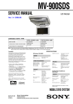
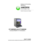
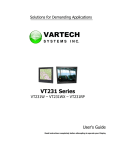
Solutions for Demanding Applications
VARTECH
SYSTEMS
I N C.
XHBV Series
8.4” – 10.4” – 12.1” – 15.1”
User’s Guide
Read instructions completely before attempting to operate your Display
Information Disclaimer
This VARTECH SYSTEMS User Manual is provided “as-is”, without warranty of any kind, either expressed or
implied, including but not limited to the implied warranties or merchantability and fitness for a particular
purpose.
Documentation Change Notice
The information in this User Manual is subject to change without prior notice in order to improve readability
and reliability as well as design and function. These changes will be incorporated in a new revision, available
from the product and/or download section of the VARTECH SYSTEMS web site, www.vartechsystems.com.
Liability
In no event will VARTECH SYSTEMS be liable for direct, indirect, special incidental or consequential damages
arising out of the use of or the inability to use VARTECH SYSTEMS’s product or its documentation, even if
advised of the possibility of such damages.
Endorsement
Product names mentioned herein are used for identification purposes only and may be trademarks and/or
registered trademarks of their respective companies.
Copyright
This document contains proprietary information protected by copyright. All rights are reserved. No part of this
manual, in whole or part, may be reproduced by any means, in any form, without prior written permission of
VarTech Systems.
Table of Contents
Safety ..................................................................................... 4
Product Care and Maintenance.................................................... 6
System Set-up ..........................................................................7
Cable Connections .................................................................. 10
Optional AC Power Adapter...................................................... 11
Operator Controls.................................................................... 12
On-Screen Display (OSD) ......................................................... 13
Optional Internal Heater .......................................................... 16
Optional NVIS Filter ................................................................. 16
Appendix A - Mechanical Drawings ........................................... 18
Appendix B - Troubleshooting ................................................... 18
Appendix C - NEMA and IP Industry Standards ........................... 19
Appendix D -Technical/Environmental Specifications.................... 20
SAFETY
General Safety Instructions
•
•
•
•
•
Before operating the XHBV Monitor, read this User Manual thoroughly
Retain this User Manual for future use
For expeditious installation, follow these User Manual instructions in sequence
Adhere to all Caution and Warnings on system and as stated in this User Manual
All User Manual instructions for installation and operation must be followed
precisely
• Adjust only those controls covered by the User Manual’s operating instructions;
improper adjustment of other controls voids the unit’s warranty and may result in unit
damage, and adhere to local installation codes.
Safety Icons
Warning! Shock Hazards
warning!
This icon is intended to tell you of a potential risk of electrical shock.
Caution! Instructional
caution!
This icon is intended to tell you of important operating and/or
maintenance instructions.
General Unit Safety
•
•
•
Always disconnect the unit from the power source before cleaning
Do not operate the unit with a damaged cord
Do not operate if the unit has been dropped or damaged. The unit needs inspected
by qualified VARTECH SYSTEMS Service Personnel
• Position the power cord so it will not be in contact with hot surfaces
• Do not allow anything to rest on the power cord, and
• Do not place the power cord where there will be foot traffic.
General Safety Precautions
warning!
•
•
•
•
•
•
Power cord must be connected to a properly wired and grounded power source
Any equipment to which the unit will be attached must also be connected to properly
wired and grounded power sources
Do not connect or disconnect the unit during an electrical storm
Do not remove the unit covers – there are no user serviceable parts in the unit
Do not disassemble or modify the unit to avoid the possibility of electrical shock,
damage to electrical components or scratching the Display surface, and
Disassembly of the unit voids the warranty.
XHBV
4
150-126
fluids from LCD Display
caution!
•
•
If the Monitor should ever become shattered, do not touch fluids from an LCD Display
If fluid should get on hands or clothing, immediately wipe off with liquid soap or rubbing
alcohol on a clean towel; wash with water; immediately consult with a doctor, and
• If fluid gets in the eyes, flush eyes immediately with water for a minimum of 15 minutes;
consult with a doctor.
Electrical
Connecting Cables
•
•
Disconnect the power when the Monitor is being installed, and
Upon installation, verify the power connector is securely seated on the unit.
Power Source
This unit may be operated from an AC or DC power source.
• Use the supplied power cable, and
• Always connect to a properly grounded power source.
EMI/RfI
caution!
This product has been engineered to meet or exceed international industry standards
addressing product design and enclosure protection against EMI/RFI when installed
with the factory provided cables.
Protection on Servicing
Servicing - User
•
•
User product servicing is limited to cleaning the unit
Do not disassemble or modify the unit to avoid the possibility of an electrical shock,
damage to electrical components or scratching the Display surface, and
• Disassembly voids the warranty.
Servicing - VARTECH SYSTEMS
VARTECH SYSTEMS Qualified Service Personnel may be required if the unit:
• Does not operate normally when installation instructions are followed
• Does not operate normally when operating instructions are followed
• Has been dropped or damaged, or
• Exhibits a distinct change in performance, indicating a need for service.
Shipping
If the unit should need to be shipped to the VARTECH SYSTEMS Service Center, the
original packing material should be used to insure safety of the unit in shipping.
Repack the unit as it would have originally been received from VARTECH SYSTEMS.
XHBV
5
150-126
PRODUCT CARE & MAINTENANCE
Product Care
This XHBV Monitor has been designed to provide optimum performance and service
without any required scheduled maintenance other than occasional cleaning.
warning!
Disconnect the Monitor from the power source before cleaning the Monitor,
optional Touch Screen or unit’s enclosure.
•
caution!
Do not use abrasive cleaners or solvent-based (flammable) cleaners on the
Flat Panel, enclosure or any other electrical device (cables, power cord, etc.)
• Do not use paper products as they may scratch the Display screen, and
• Do not directly apply cleaning solutions to the Display screen.
Display Screen Cleaning
•
•
•
•
A vinegar-based cleaner is preferred: prevents streaking, degradation of coatings
A non-abrasive glass cleaner may be used, as in a professional foam glass cleaner
Apply the cleaning solution to a soft clean cloth, dampening slightly
Keep a fresh side of the cleaning cloth towards the screen surface to avoid
scratching it with accumulated grit, and
• To minimize the risk of abrasion to the screen, air drying is recommended.
In marine or similar environments, an added benefit of a vinegar-based
cleaner is its effectiveness in dissolving mineral and salt deposits.
Monitor Enclosure
•
•
Clean the unit enclosure with a soft clean cloth lightly dampened with a general
purpose mild detergent solution
Wipe down with clean water; dry with a soft clean cloth.
warning!
To avoid risk of electrical shock, do not disassemble the unit’s enclosure. Users
cannot service the Monitor. User maintenance is restricted to cleaning or power
cord replacement, as explained. Disassembling the unit voids the warranty.
Long-term Storage
• For long-term storage, it is suggested the unit be stored in a normal indoor environment and the Display glass be protected from accidental damage
• For pedestal mount units, disconnect the cable(s) and loosen the arm adjustment
to a point where the ball can be removed from the arm, or For Flush or Panel
Mount units, cover the product with a protective covering that will not scratch or
transfer any dyes to the Display screen.
Maintenance
Other Maintenance
Only VARTECH SYSTEMS Qualified Service Personnel should perform all other
maintenance except for cleaning and the power cord replacement described below.
Power Cord
warning!
XHBV
To avoid shock and fire hazards, replaced the unit’s power cord if:
• Insulation becomes damaged, or
• A loose connection is suspected.
6
150-126
SYSTEM SET-UP
System Requirements
The XHBV accepts a standard NTSC composite video signal from any device –
a camera, VCR or DVD.
Shipping Box Contents
The XHBV is shipped in a custom box with custom foam packaging. It is recommended the installer save the box and all packaging materials in case the unit would
need to be returned to the VARTECH SYSTEMS Service Center.
The shipping box contents are:
• XHBV unit
• Power Cable
• Mounting System and Hardware
• User CD
XHBV
7
150-126
The XHBV is designed to be mounted with a universal ball-and-socket mounting kit,
in a Flat Panel position or optional Flush Mount configuration.
Pedestal Mount
The XHBV is shipped with a RAM® universal ball-and-socket system mounting kit
(Figure 1). By installing the Monitor with this kit, the User can quickly adjust the
viewing angle to improve viewability in changing environments. This ball-and-socket
system has proven to be successful in supporting an extreme amount of weight in high
vibration and difficult-mount applications.
Locate the ball-and-socket system in the shipping box. The kit consists of two RAM
balls on mounting plates and a RAM arm, with an adjustable T-knob and a packet of
three (3) M4 x 10 counter-sunk stainless screws for mounting to the XHBV.
(Figures 1 - 3)
Mounting Holes
figure 1
Ball and
Socket
Mount Only
Panel
Mount Only
figure 2
XHBV
figure 3
8
150-126
There are three mounting holes in the back of the Monitor for the ball mounting plate.
Take care not to strip the screw holes or over tighten. (Figure 3)
• Note the location of the three mounting holes on a ball mounting plate (Figure 3)
• With three (3) M4 x 10 counter-sunk stainless screws attach this mounting plate to
•
•
•
•
•
the back of the XHBV
Mount the second ball mounting plate where the Monitor will be installed
Insert each ball into the RAM arm
Lightly tighten the arm around the balls using the T-knob on the arm (Figure 1, 3)
Adjust the Monitor to the viewing preference, and
Tighten the T-knob to hold the Monitor in position.
It is recommended the remaining ball be mounted on a flat surface. Because of the
various surface substrates the Monitor will be mounted on, the installer will provide
the screws to mount the other ball.
Panel Mount
The Panel Mount installation should be specified at the time of order; the ball-andsocket mount system will not be included in the shipping box.
The mounting hardware packet is included with the unit accessories in the shipping box.
This packet includes four (4) threaded screws (approximately 7.6 cm [3”] long), four (4)
Nylock nuts and four (4) flat washers. For installation, there are four tapped mounting
holes on the four corners of the unit’s rear panel.
caution!
Take care not to strip the
screw holes or over tighten
as the enclosure is aluminum.
Flush Mount with Optional Bezel
With the Flush Mount Bezel, the XHBV Flat Panel Display may be mounted flush with the
mounting surface; the ball-and-socket mount system or any mounting hardware will not
be included in the shipping box. The installer needs to supply screws for this type of
installation.
Note the locations of the milled holes in the Flush Mount Bezel. Drill corresponding
holes into the substrate where the Monitor is to be mounted.
caution!
XHBV
Take care not to strip the
screw holes or over tighten
as the enclosure is aluminum.
9
150-126
CABLE CONNECT
Cables
• The XHBV is packaged with one cable:
DC Power, #1 in Figure 4
• The BNC cable and S-Video cable, #2 and 3 in
Figure 4, are provided by the end-user, and
• The AC Power Adapter is optional. (Figure 5)
1
2
3
DC Power Input
BNC Input
S-Video Input
caution!
Use care when inserting or
removing connectors.
1
2
3
figure 4
figure 5
Connectors
Connectors are located on the bottom of the unit housing, from left to right:
BNC, S-Video and Power. (Figure 6)
Connectors are physically unique to insure the installer makes the proper connections.
1
2
3
1
2
3
BNC Input
S-Video Input
Power Input
figure 6
Composite BNC Connector
The XHBV accepts a standard NTSC composite video signal from any device –
a camera, VCR or DVD. This signal is carried to the Monitor via a coaxial video
terminated with a BNC connector.
•
The end-user supplies the BNC coaxial video cable
•
The BNC receptacle on the Monitor is sealed
•
Line up with first connector, #1 in Figure 6, and
•
Plug together, adding a ¼ twist to lock the two pieces.
XHBV
10
150-126
S-Video Connector
•
•
•
•
A standard S-Video component cable is required for installation
The IP68 sealed S-Video connector is #2 in Figure 6
The flat side of the connector lines up with the connector’s rectangular bar, and
Plug the connectors together.
DC Power Connector
•
•
•
•
The IP68 sealed DC Power Cable, 3 m (10 ft), is in the accessory box
Line up the red dots to #3 in Figure 6
Plug in the quick-connect 3-pin connector
To disconnect, pull the outside ring on the connector away from the unit until the
cable is free
•
The positive flying lead is marked
with a “+” label. The negative lead is
not marked (Figure 7).
•
Connect the flying leads to the corresponding polarity on the DC voltage
source, primary terminal.
figure 7
warning!
Verify the polarity of the power source posts prior to attaching the power cable’s
flying leads.
OPTIONAL AC POWER ADAPTER
Optional AC Power Adapter
•
•
•
•
•
•
The optional AC Power Adapter Cable Set consists of a 3 m (10 ft) cable with
an IP68 sealed connector, the power adapter and a 1.8 m (6 ft) common AC
power cord (Figure 6)
The adapter accepts voltage from 110 to 250 VAC and frequency from 47 to 63Hz
The AC power cord plug is a North American standard for 120 VAC/60Hz, and
Line up the red dots to #3 in Figure 7
Plug in the quick-connect 3-pin connector, and
To disconnect, pull the outside ring on the connector away from the unit until free.
Note: The optional AC Power Adapter is not an off-the-shelf item. It is equipped with a
specific connector for integration with the XHBV monitor.
XHBV
11
150-126
Operator Controls
On the right hand side of the Monitor bezel
are six Operator Control buttons (Figure 8).
Power Button
Note: Monitor defaults to an AUTO-OFF state
when power is applied.
Power On/Off (I/O)
Button
Large sun
• The Power On/Off button is marked with
the I/O (Input/Output) symbol
• Momentarily pressing this button will
turn ON or turn OFF the unit, and
• A Red LED located under the I/O button
glows when the unit is powered on.
Brightness
Control
Small sun
Select Button
Optional feature: Monitor defaults to an
Right Button
AUTO-ON state when power is applied. This
feature must be ordered when the Monitor
order is placed. It is not available after the
unit is built.
Left Arrow
figure 8
Brightness Buttons
These buttons control the brightness of the LCD Panel Display.
• The LARGE SUN button, when repeatedly pressed or held down causes the
display’s LCD panel backlight brightness to be stepped up in increments to its
brightest setting
• The SMALL SUN button, when repeatedly pressed or held down causes the
display’s LCD panel backlight brightness to be stepped down in increments to its
lowest setting, which is just above total black, suitable in very subdued light, as in
night time operations, and
• Adjusted settings are maintained when the unit is powered off, then powered on.
Adjust the brightness of the Display to the lowest possible setting for
a given set of conditions and display characteristics. Doing so will
provide the best viewing of the image, extend the lamp life of the
backlight and reduce the internal heat of the Display.
Select Button
The SELECT Button is the access point to the On-Screen Display (OSD) Source Screen
Function Menu. (See On-Screen Display.)
Press the SELECT button twice to access the Video Source Menu, to move between
video inputs, Composite and S-Video.
Right Arrow Button
The RIGHT Arrow Button is an adjustment tool in the On-Screen Display (OSD) Source
Screen Controls Menu. (See OSD Screen Control Menu Categories.)
Left Arrow Button
The LEFT Arrow Button is an adjustment tool in the On-Screen Display (OSD) Source
Screen Controls Menu. (See OSD Screen Controls Menu Categories.)
XHBV
12
150-126
ON-SCREEN DISPLAY
The On-Screen Display (OSD) User Interface is where display signal source adjustments are made. The Source Screen Controls Menu provides access to fine-tuning
the display.
OSD Source Screen Controls Menu Activation
To activate the OSD Source Screen Controls Menu in the active video source, press
and release the SELECT button.
Note: OSD Source Screen Controls Menu will close after 15 seconds of inactivity.
OSD Source Screen Controls Menu
The Controls Menu is comprised of seven source screen control categories with
adjustable settings.
Display Category Adjustments
• Press the SELECT button to access the Controls Menu
• In the Controls Menu, to choose a Display Category, use the RIGHT or LEFT Arrow
button to move UP or DOWN the Controls Menu
• The Controls Menu item changes color, from black to red, when it is active
• When a Controls Menu item is in red, press the SELECT button to open
• The adjustment controls are the RIGHT and LEFT Arrow buttons, which increase or
decrease the value of the menu item’s parameter as noted in the indicator screen
• Create the new parameter value
• Press the SELECT button to save the new value; this returns the User to the Controls Menu
• Move the RIGHT or LEFT Arrow button to move to another Controls Menu item, or
• Move the RIGHT or LEFT Arrow button to Exit.
OSD Source Screen Controls Menu Categories
•
caution!
New settings will be stored in memory upon pressing the SELECT button to
exit the OSD Source Screen Controls Menu item.
•
If SELECT is not pressed, or inactivity is detected within the 15 second
factory default OSD menu duration, any screen function adjustments made
will be saved.
Controls Menu Parameters
Video Horizontal
Video Horizontal adjusts the picture screen, left to right.
• Open the “Video Horizontal” function, and
• Press the RIGHT or LEFT Arrow button to adjust the display’s horizontal position.
Video Vertical
Video Vertical adjusts the picture screen, top to bottom.
• Open the “Video Vertical” function, and
• Press the RIGHT or LEFT Arrow button to adjust the display’s vertical position.
XHBV
13
150-126
It is recommended to adjust the LED back light brightness
to maximum before fine-tuning the OSD Source Screen
Controls Menu Parameter: Brightness.
Video Brightness
Before adjusting the Video Brightness parameters, set the LCD panel back light
brightness using the LARGE SUN button; set to its brightest in the ambient light
source.
• Open the “Video Brightness” function, and
• Press the RIGHT or LEFT Arrow button to set the Display’s desired brightness.
Video Blacklevel
Video Blacklevel adjustment intensifies or decreases the saturation of black.
• Open the “Video Blacklevel” function, and
• Press the RIGHT or LEFT Arrow button to set the Display’s desired black level.
Video Contrast
Video Contrast is the difference in brightness between the light and dark areas of the
pixels of the picture.
• Open the “Video Contrast” function, and
• Press the RIGHT or LEFT Arrow button to set the Display’s desired contrast.
Video Hue
Video Hue is the pinks, blues and greens of the Display.
• Open the “Video Hue” function
• Press the RIGHT or LEFT Arrow button to set the Display’s desired tint, and
• Ranges on the Display bar are: low – pinks; mid-range – greens and upper – blues.
Video Color
Video Color adds or subtracts color values from the picture.
• Press the LEFT Arrow button to remove color and go to black and white, and
• Press the RIGHT Arrow button to add color.
Recall
The Recall feature resets the Controls Menu items to factory default.
• Select “Recall“ control to reset all the controls to factory default, and
• Press the SELECT button to save changes.
Exit
The Exit menu item takes the User out of the Source Screen Controls Menu.
• Press the RIGHT or LEFT Arrow button to get to Exit, and
• Press the SELECT button to Exit.
XHBV
14
150-126
Video Source Menu
The Source Screen Video Source Menu gives the menu for the Monitor’s video source
selections.
Composite Video
• Press the RIGHT or LEFT Arrow button to select “Composite Video“ signal, and
• Press the SELECT button to open this source Controls Menu.
S - Video
• Press the RIGHT or LEFT Arrow button to select “S-Video“ signal, and
• Press the SELECT button to open this source Controls Menu.
Exit
The Exit menu item takes the User out of the Source Screen Video Source Menu.
• Press the RIGHT or LEFT Arrow button to select Exit, and
• Press the SELECT button to Exit.
XHBV
15
150-126
OPTIONAL INTERNAL HEATER
Optional Internal Heater
The optional Internal Heater automatically brings the Monitor up to the standard
operating temperature if the unit is below that temperature when powered on.
Operations
•
The flashing blue LED lights behind the Operator Control Buttons indicate the unit
is in the heating mode, bringing the Monitor up to operational temperature
• Once the Monitor is up to operational temperature, the flashing blue LEDs become
a constant blue glow and the unit automatically powers on
• Maximum time for the unit to reach operational temperature is approximately
12 minutes, and
• There are no User adjustments for the Internal Heater function.
OPTIONAL NVIS FILTER
Optional NVIS Filter
The optional Night Vision Imaging Systems (NVIS) filter on VARTECH
SYSTEMS Monitors is in compliance with the NVIS radiance value
requirements of MIL-STD-3009 and MIL-L-85762A for Type 1, Class B,
electro-optical displays.
This means the optional NVIS filter is compatible with Night Vision Goggles (NVGs).
XHBV
16
150-126
APPENDIX A
Mechanical Drawings
Mount diagrams of the XHBV and its dimensions may assist with the installation of
the Monitor.
Optional Flush Mount Bezel
Mount diagrams of the Flush Mount Bezel and its dimensions may assist with the
installation of the Monitor.
APPENDIX B
Troubleshooting
Symptom: No light behind button LEDs
Possible Problem
Solution
No power, loose power connection
Confirm the Monitor is properly connected to a
DC or AC power source.
Verify the power source is live or try another
battery or AC power outlet.
Verify the Monitor is powered on.
Reverse polarity
Check polarity of the power connection.
Symptom: Light behind button LEDs, no display, or “No Signal” error
message and/or no image on the display
Possible Problem
Solution
Power on, no video signal
Verify a video signal is coming out of the signal
source (i.e., plug into a known good display
source).
Verify the incoming signal source selected
matches the Monitor signal source (Composite,
S-Video).
Check the Brightness front panel setting on the
Monitor. This may be set too low.
Check the Brightness and Contrast controls in
the OSD. These may be set too low.
XHBV
17
150-126
Symptom: Display has rolling “bars” across the screen or vertical
shaded bars on the image
Possible Problem
Solution
Defective video cable
On a known good display source, confirm the
video cable is not defective.
Interference from adjacent equipment
For proper grounding and shielding, verify use
of a proper video cable.
Keep the cable away from sources of EMI
such as electric motors, or unshielded RFI
sources such as radar and microwave.
Horizontal size is not adjusted
In the OSD, adjust the Video Horizontal
controls.
Symptom: Picture quality, image stability is distorted
Possible Problem
Solution
Proper cable grounding and shielding
Verify the use of a proper video cable with
suitable grounding and shielding. Keep the
video cable away from sources of EMI and
RFI.
Improper video display settings
Check signal source for proper signal.
Check for proper display properties selection.
Display unit is farther than 3 m (10 ft) from
signal source
Multiple Monitors are driven from the same
signal source.
Monitor has incorrect or bad sync signals.
Single cable lengths in excess of the standard
3 m (10 ft) cable should be of high quality
shielded cable. Contact VARTECH SYSTEMS
for information
on custom cables
Splitting the video signal divides the strength
of the signal. A video signal booster (line
driver) is recommended if installation requires
more than one Monitor driven from a single
video source.
Check for proper video cable installation, or
replace suspected faulty cable.
Symptom: Display image is not properly sized
Possible Problem
Solution
OSD adjustments need to be made
Adjust the Video Vertical and Horizontal
controls through the OSD.
XHBV
18
150-126
APPENDIX C
NEMA and IP Industry Standards
There are two major electrical manufacturing organizations monitoring product
enclosures and/or their degree of protection; each organization also publishes technical manufacturing standards. The National Electrical Manufacturers Association
(NEMA) Standard No. 250 – 2003 addresses non-hazardous locations, enclosure
design and its environmental performance requirements. These are referred to as
NEMA Types. (www.nema.org)
The International Electrotechnical Commission (IEC) 60529 Standard addresses
Ingress Protection (IP); this describes the degree of enclosure protection provided,
not the enclosure itself. The first digit of the IP Code designation describes the degree
of protection against the ingress of solids; the second digit designates the degree of
protection against the ingress of liquids. IP Codes support NEMA Type designations.
(www.iec.ch)
VarTech Systems designs the XHBV sealed monitor to exceed the Stand- ards of
NEMA 6P and IP68, incorporating a range of environmentally-sealed connec- tors
engineered to provide a safe and secure dust and waterproof environment in rugged
conditions.
Summary of NEMA 6P/IP 68: Enclosures constructed for indoor or outdoor use; to provide a degree of protection to personnel against incidental contact with the enclosed
equipment; to provide a degree of protection against falling dirt; against hose-directed
water and the entry of water during occasional prolonged submersion at a limited
depth; and that will be undamaged by external formation of ice on the enclosure.
XHBV
19
150-126
APPENDIX D
Technical Specifications
8.4”
Display
TFT AM, SVGA, LCD, 256K
Colors. 800 x 600 pixels
10.4”
12.1”
D
D
700 nits,
Transflective,
AR/AG
Sunlight
Readable
800 nits, Transflective, AR/AG
Dimming
Ratio
100:1
D
D
NTSC/PAL (B,D, G, I, K)
D
D
D
D
Milled Aluminum, Black Anodized,
UV Clear Coat
D
D
Panel Mount or RAM Mount
D
D
D
D
D
D
D
D
Video Input
D
BNC
Connectors
Housing
Mounting
S-Video
JAE to Flying leads DC Input
(Optional Flush Mount)
Power
6 Watts Min - 20 Watts Max
Consumption
Wide Range
DC Power
Input
Power
Conditioning
XHBV
8-30 VDC
(12, 24, 28 VDC nominal)
Internal Short Circuit Protection
Load Dump Protection
Over Voltage Protection
Reverse Polarity Protection
20
150-126
Environmental Specifications
8.4”
10.4”
12.1”
Operating
Temperature
0°C to 60°C (32°F to 140°F)
D
D
Operating
Tempature
w/ Internal
Heater
Option
-40°C to 60°C (-40°F to 140°F)
D
D
Storage
Temperature
-40°C to 75°C (-40°F to 167°F)
D
D
Shock
50 G
D
D
Vibration
5.8 G (5-500 Hz)
D
D
IP Rating
IP68 (NEMA 6P Submersible)
D
D
Humidity
0-100%
D
D
EMI
Designed to meet FCC B, CE
D
D
Altitude
45,000 ft.
D
D
XHBV
21
150-126
9.900 (Display
CONTACT
Vartech Systems Inc
11529 Sun Belt Ct
Baton, Rouge, LA 70809
Phone: 225.298.0300
Toll Free: 800.223.8050
Fax: 225.297.2440
Email: [email protected]
www.vartechsystems.com